|
|

Table Of Contents
ANA Overview
The following topics will introduce you to the Cisco Active Network Abstraction (ANA) product. These topics explain what ANA is, how you can use it to manage your network resources, and how ANA differs from other network and element management systems. These topics also introduce you to terms with which you should become familiar, and how they make up the ANA architecture. Finally, you will be introduced to the perspectives provided in the ANA user interface.
If you have already installed ANA, and performed the necessary setup tasks, you can proceed to ANA Administration, page 14-1.
What is ANA?
ANA is a resource management platform that serves as an active mediation layer between the operation and network layers. It provides a set of easy-to-use applications and well-defined APIs for Operations Support Systems (OSS). ANA enables service providers to efficiently respond to the constant market demand for new, reliable, and more complex services, while hiding the complexity of large, multivendor, mixed technology networks.
ANA can manage diverse network environments. It offers an integrated process for network modeling, intelligent fault analysis, and a highly flexible network configuration and activation engine. This enables fully correlated management of global scale networks that need to support millions of subscribers and customers.
ANA is a network management system that provides a fully integrated, service-oriented offering including:
•
Multivendor network element support (physical components that can be managed through an IP address)
•
•
•
Based on a patented architecture of distributed autonomous virtual network elements (VNEs), ANA enables integration management for multivendor, multitechnology network environments, while at the same time scaling according to network growth and evolution. (For a description of VNEs, see ANA Architecture.)
ANA hides the complexity of large, multivendor, mixed technology networks while allowing you to constantly modify your network in response to the constant market demand for new, reliable, and more sophisticated services. The user interface (UI) provides a normalized view of network elements and the network, masking differences and nuances of diverse network element types and vendors. This makes it easier to view the status, control the configuration, and manage the state of the network and intranetwork element operations.
How You Can Use ANA
The ANA GUI client applications help you to manage assurance, configuration, and performance of your network. ANA provides standards-based northbound APIs for support integration with OSS and BSS applications. The APIs include a Web Service-based API for inventory, provisioning, and fault OSS integrations.
ANA also provides an SNMP trap forwarding API that provides the ability to send traps to fault management OSS applications. It is a fully distributed solution that implements parallel processing by creating a virtual model of the network. Your network can continue to grow as you add more autonomous VNEs and units to support network growth.
The following sections describe the main ANA functionalities.
Network Topology and Inventory
ANA provides views of network topology and inventory information for all network elements being managed.
An autodiscovery program can be used to query the network using networking technologies or seed devices, and discovers all network elements. It then creates the seed file needed to populate the ANA system with information required to manage the network elements.
After the network elements are managed, ANA further discovers network topology and the logical inventory of the network and network elements. You can then browse both the physical and logical inventories and view the topology.
ANA provides rich functionality to display and manage topology by providing:
•
•
•
•
•
Administrators can create multiple network domain maps in order to represent specific network and topology views. These network domains can cover specific network segments, customer networks, or any mix of network elements desired. After the network domain maps have been created, they are available for all connecting clients (based on user privileges). ANA supports Cisco network elements, along with network elements from multiple vendors, across multiple technologies, forming a unified, end-to-end representation of the network. ANA also supports Layer 1 to Layer 3 topologies, including simulations of packet routing and path tracing.
ANA Service Path Trace enables end-to-end route tracing. After ANA Service Path Trace receives a path's start and endpoint, it visually traces the route through the network. For more information about ANA Service Path Trace, see Tracing the Packet Path, page 11-1.
Using the Soft Property Builder, you can extend and customize the set of supported properties for each network element by adding new soft properties to the VNEs. These properties extend the ANA model and are available through the GUI client.
In addition, alarm thresholding enables you to constantly monitor selected properties and generate an alarm every time a network element crosses a user-defined threshold or violates a condition. For more information on Soft Properties, see Customizing Network Element Information Using Soft Property Builder, page A-1.
You can also use APIs to provide physical and logical inventory information to northbound systems, including setting business tags, providing topology links, and subscribing to inventory change notifications.
Faults
ANA detects and identifies faults in the network using a combination of traps, syslogs, and heartbeat-type polls to the network elements. After interpreting these events and applying correlation rules, ANA uses the Ticket Browser and the Alarm and Event viewers to display active alarms in the network.
In addition, alarm status is propagated to the representation of the network element in the Object Tree View and network domain maps.
The following terms are central to ANA fault management:
•
•
•
When an alarm is raised, ANA correlates it using the network topology and inventory to determine the alarm's root cause, and analyzes the network elements to locate any elements that may be impacted by the alarm.
ANA removes duplicate alarms that result from the same cause. A ticket is identified by the top-most alarm. When you view a ticket in the ANA user interface, you can drill down to review the consequent alarms. For more information, see Tracking Faults, page 12-1.
For northbound systems, you can forward ANA events in SNMP V2 trap format and subscribe to event and ticket notifications across the Web Service-based API.
Configuration
ANA configuration components provide the ability to monitor and make changes to network elements. Configuration components include:
•
•
•
Performance
You can use ANA to perform on-demand collections of performance statistics, and then display them in the inventory. You can extend and customize the data that is collected for different network elements using the Soft Property Builder. You can also customize alarm thresholds to monitor selected properties and generate an alarm every time a network element crosses a user-defined threshold or violates a condition.
Administration
The system provides infrastructure software and tools for scheduling jobs, logging, auditing, backing up and restoring data, and managing licenses. Administrators can create users and control permissions by assigning these users a combination of predefined roles and scopes:
•
•
ANA also provides a high availability mechanism to protect the system in case a unit malfunctions. If the unit is configured for high availability (by being assigned to a protection group), ANA switches over to the standby unit, with no loss of information to the system.
ANA Architecture
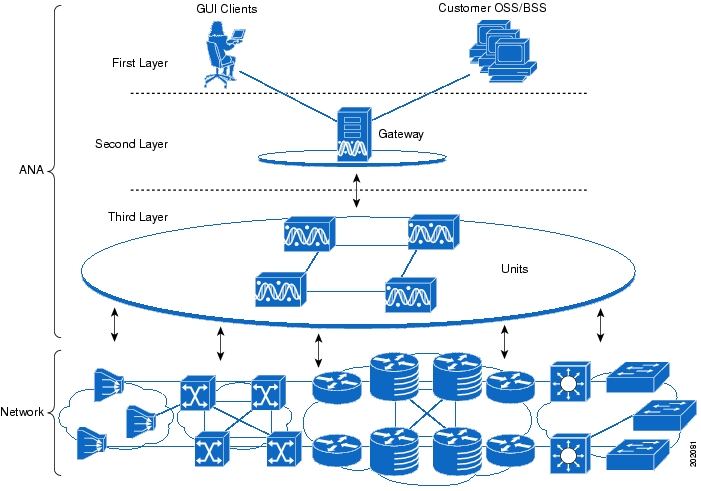
Figure 1-1 illustrates the ANA platform's three-layer architecture.
Figure 1-1 ANA Architecture
First Layer
The top layer comprises the commercial and legacy OSS and BSS applications, as well as the ANA clients. The ANA solution enables OSS and BSS applications to integrate with the platform, via a set of well-defined, standards-based APIs.
Second Layer
The second layer comprises the gateway server, through which all the OSS and BSS applications and ANA GUI clients access the ANA fabric. Each client connects to its designated gateway. The gateway acts as the portal through which all clients, including any OSS and BSS applications, access the system. It enforces access control and security for all connections and manages client sessions.
The gateway server maintains a repository for keeping system settings, topological data, and snapshots of active alarms and events. Another important function of the gateway is to map network resources to the business context. This enables ANA to contain information (such as VPNs and subscribers) that is not directly contained in the network and display it to northbound applications.
The gateway also contains the alarms and events in the system. For information on managing the gateway, see Managing the Gateway, page 2-7.
Third Layer
The third layer comprises the interconnected fabric of unit servers. Each unit manages a group of network elements. The units are distributed in a way that ensures proximity to their network elements. The gateway is connected to the units, which host the autonomous VNEs.
The units are interconnected to form a fabric of VNEs, which can intercommunicate with other VNEs regardless of which unit they are running on. Each unit can host thousands of autonomous VNE processes, depending on the server system size and VNE type.
The units also allow for optimal VNE distribution, ensuring geographic proximity between the VNE and its managed network element. ANA also provides a high availability mechanism to protect the system in case a unit malfunctions. If the unit is configured for high availability, ANA switches over to the redundant standby unit, with no loss of information. For more information about high availability, see Managing Protection Groups (for Unit High Availability), page 14-9. For information on managing units, see Managing Units (and High Availability), page 2-8.
Within the units are AVMs. AVMs are Java processes that provide the necessary distribution support platform for executing and monitoring multiple VNEs. AVMs and VNEs should reside on an ANA unit (as a common configuration) but they can also reside on an ANA gateway. For information on managing AVMs, see Managing AVMs, page 2-11.
The VNEs are the entities that maintain a live model of each network element and of the entire network. A VNE is a software entity that runs as a completely autonomous process within an ANA unit. Each VNE is assigned to manage a single network element instance, and contains a replica of that element. The VNE uses whatever southbound management interfaces the network element implements (for example, SNMP or Telnet). For information on managing VNEs, see Managing VNEs, page 2-17.
Getting Started
To view network elements using the ANA user interface, you must do the following:
Note
1.
–
–
2.
3.
Once you have added network elements and created a network map, you can begin monitoring your elements, viewing tickets, getting details about network elements, and so forth.
The following list gives examples of other tasks you may want to perform, and the topics in which they are described.
Check the status of your network
Generate a report of the entire inventory
Change or update software images on network elements
Back up and restore network element configurations on an automated basis
Find out what changes occurred on a network element configuration by generating a comparison report
Get details about a specific network element's inventory
Change the credentials ANA uses to communicate with network elements, or unmanage an element
Configure a network element using activation scripts
1.
Apply an existing activation script to other network elements
Using the Workflow Editor to Create Task Workflows, page B-1
Configure ANA to raise an alarm when a network element attribute crosses a specific threshold
Check the performance of the ANA system
Manage licenses
Cisco Active Network Abstraction 4.0 Installation and Setup Guide
Using the ANA UI
These topics describe basic guidelines for using the ANA UI; for example, launching online help, moving between perspectives, using filters and search, and so forth:
•
This information will help you understand the purpose of the various perspectives and how to use the basic UI features. It also explains how to roll back your UI changes if you have closed certain UI elements and do not know how to retrieve them.
Perspectives
Related functions are grouped together in the different ANA perspectives. For example, the Monitoring perspective provides the functions you need to get the overall status of your network resources. If a problem arises, you can get detailed information about the problem from the Troubleshooting perspective. If you want more information on the configuration of a specific network element, you can go to the Inventory perspective. If you need to perform any administration tasks, you go to the Administration perspective.
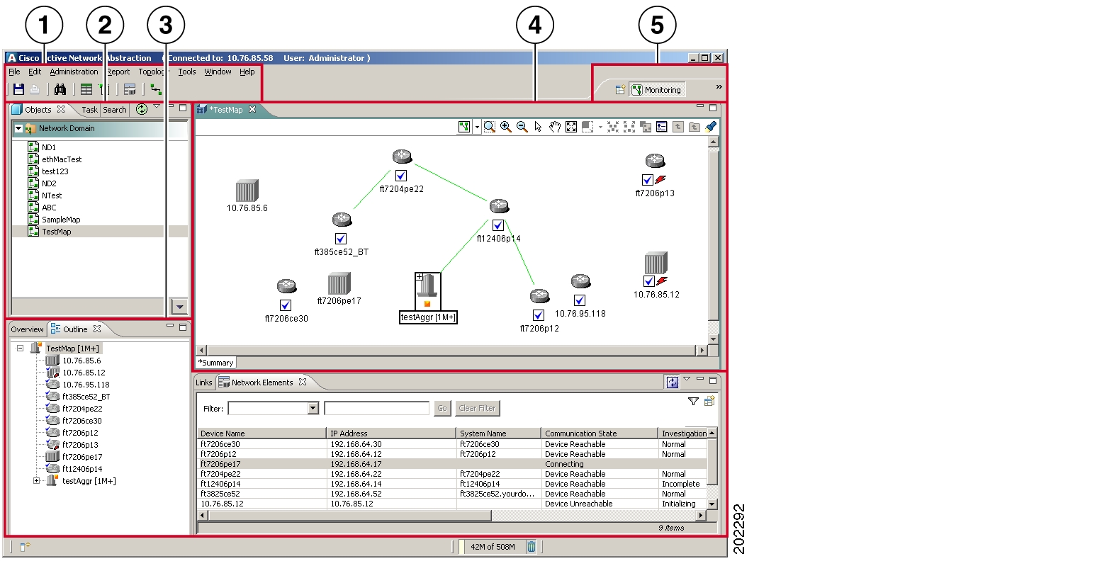
All ANA perspectives conform to the structure shown in Figure 1-2. How the instance of a perspective actually looks depends on what you have selected or the function you are performing, and whether you have moved or customized the user interface.
Note
Figure 1-2 Structure of ANA Perspectives
1
Main menu and toolbar.
2
Navigation area and corresponding toolbar.
3
Supporting views and their local toolbars.
4
Workspace and corresponding toolbar.
5
Perspective selector bar.
The perspective selector bar is at the top right of the ANA window. The selector bar displays the name (and representative icon) of the perspective that is currently active, as shown in Figure 1-3.
Figure 1-3 Changing Perspectives
To change perspectives, click the icon to the left of the current perspective's name and choose another perspective. You can also select a perspective by choosing Window > Open Perspective from the main menu. If you will be moving between perspectives, drag the perspective selector bar to the left to display all perspectives.
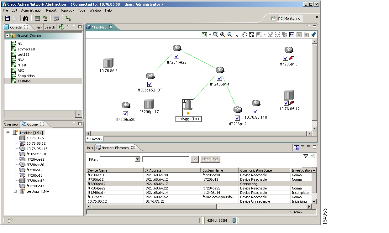
Monitoring Perspective
The Monitoring perspective displays topological network data—a "big picture" view—of elements and their relationships. Icons and colors indicate element types and states. Administrators can create network domains and maps to provide specific network views (specific network segments, customer networks, and so forth). The tickets and events displayed in this window are similar to those displayed in the Troubleshooting perspective, but with limited operations. You can use this perspective to create static links between elements. You can also launch reports and check on jobs using this perspective.
Figure 1-4 Monitoring Perspective
To enable users to see a topological view in this perspective, administrators must first add some network elements to ANA so they can be managed, and then create a network domain map containing those elements. For more information on using the Monitoring perspective, see Working with Topology Maps, page 5-1.
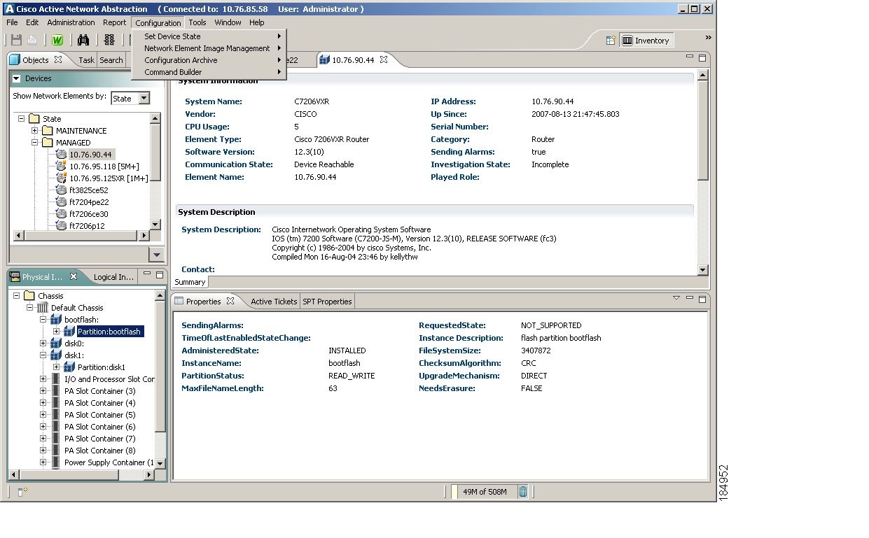
Inventory Perspective
You can use the Inventory perspective to view individual network elements and perform task-based flows on network elements or specific tasks on specific elements. The tickets and events displayed in this window are similar to those displayed in the Troubleshooting perspective, but with limited operations.
Figure 1-5 Inventory Perspective
For information on using the Inventory perspective, see the following:
•
•
•
•
Troubleshooting Perspective
The Troubleshooting perspective provides tasks and views to help monitor network health and manage the network and network elements when problems occur. In addition to troubleshooting network and network element problems, you can also use this perspective to troubleshoot user and application problems. Tickets removed from the Inventory and Monitoring perspectives are not removed from this perspective.
Figure 1-6 Troubleshooting Perspective
For more information on the Troubleshooting perspective, see Understanding the Troubleshooting Perspective, page 12-7.
Administration Perspective
The Administration perspective provides tools to create the ANA system of gateways, units, AVMs, and VNEs. You can use this perspective to run an autodiscovery process to find network elements, and then add them to ANA using the seed file import. This perspective also controls the administration of users and scopes (groups of network elements which users can view and manage), and the system settings that are used across ANA, such as trap forwarding, polling groups, and protection groups (which control unit failover). Use this perspective to administer jobs and configure default settings for applications (for example, the default import directory for software image uploads).
Figure 1-7 Administration Perspective
For more information on the Administration perspective, see ANA Administration, page 14-1 and ANA Administration, page 14-1.
Navigating the User Interface
Perspectives, describes how to change perspectives, and the structure of ANA perspectives. The following topics describe other elements and tasks that are common to all ANA perspectives:
•
Using the Objects and Tasks Tabs
As illustrated in Figure 1-2, the navigation area controls what is displayed in other parts of a perspective. Each perspective's navigation area has an Objects tab and a Tasks tab. These tabs provide different work paradigms:
•
•
You can view the progress of your tasks using the Progress view. You can enable this view using Window > Show View > Other > Progress View.
If one of your tabs has disappeared, it is likely that you either minimized it or converted it to a Fast View. To remediate this, see Customizing the UI.
Using Search
The search icon in the main toolbar searches for objects across all ANA perspectives.
Performs a global search.
Opens the Search dialog box and displays your last search criteria.
ANA provides a robust set of search criteria for different objects and object properties, depending on the features that are included with your system. The object you are searching for determines which attributes you can use for your search. For example, if you are searching for a device, you can search by IP address, system name, communication state, and so forth. If you are searching for a customer, you can search by name or contact.
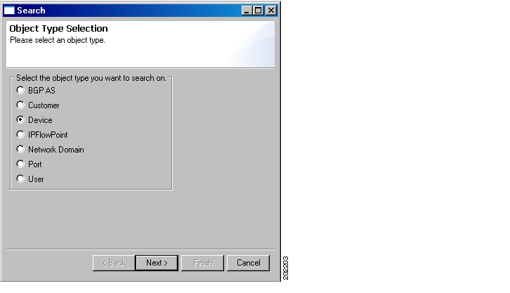
When you click the search icon, the Search Object Type Selection dialog box opens, as shown in Figure 1-8.
Figure 1-8 Search Object Type Selection Dialog Box
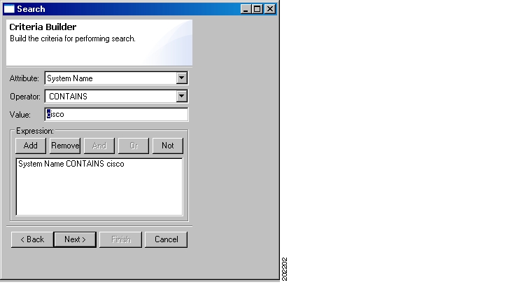
In this example, you are searching for a specific device. When you click Next, the Search Criteria Builder dialog box is displayed, as shown in Figure 1-9.
Figure 1-9 Search Criteria Builder Dialog Box
The operators that ANA displays depend on the attribute you select. The following explains the operators.
Note
You can view your search results in an abbreviated or detailed form. The results are displayed on the Search tab in the navigation area.
Some ANA functions provide specialized search tools, such as the search tool for finding an object in a topology map. These search tools are described in the topics that describe those specific functions.
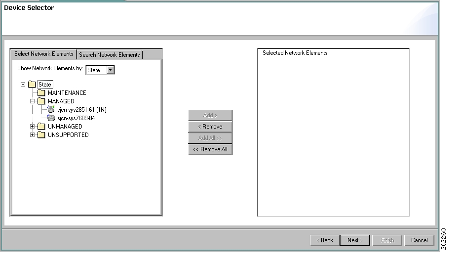
Using the Device Selector
The ANA Device Selector provides a user-friendly interface for searching for and selecting network elements so you can perform operations on them. All network elements known to ANA are listed.
Selecting Devices from Groups
Use the Select Devices tab to select from network elements that are grouped by:
•
•
Figure 1-10 illustrates a Device Selector that displays network elements according to state.
Figure 1-10 Device Selector—Select Network Elements
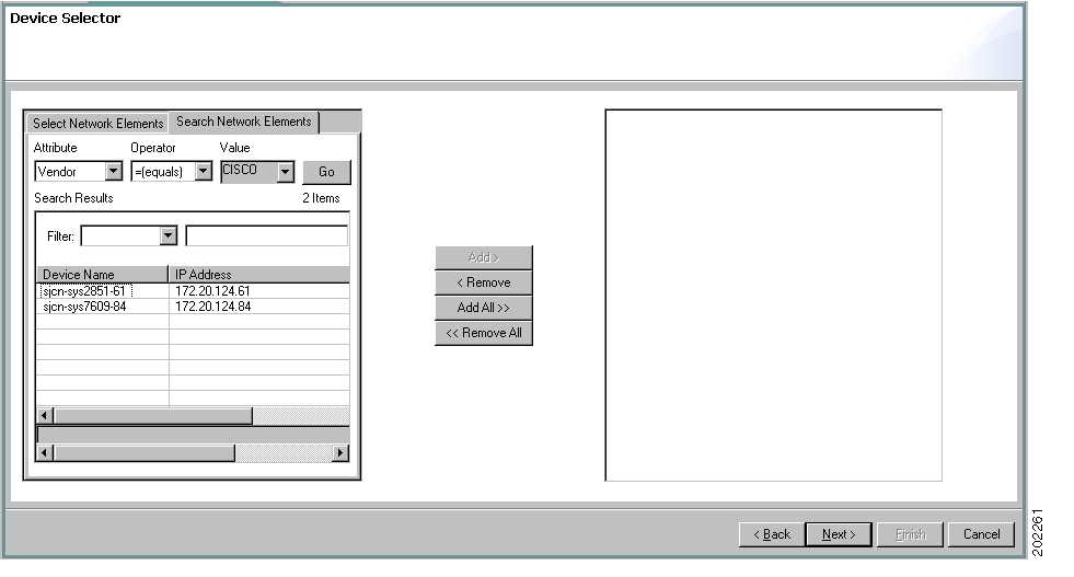
Selecting Devices Based on a Search
Use the Search Devices tab to search for network elements based on attributes, operators, and values you specify, as shown in Figure 1-11.
Figure 1-11 Device Selector—Search Network Elements
Note
The list of network elements displayed in the Device Selector depends on a user's role and scope. The Device Selector is dynamically updated when new network elements are imported into ANA. If a device is not supported in ANA, it is placed in the Unsupported group; you cannot perform any operations on unsupported devices. For a list of network elements supported by ANA, see Cisco Active Network Abstraction VNE Reference Revision 1.0.
Using Filters
You can filter results displayed in a specific view (rather than across perspectives) to quickly find the data in which you are interested.
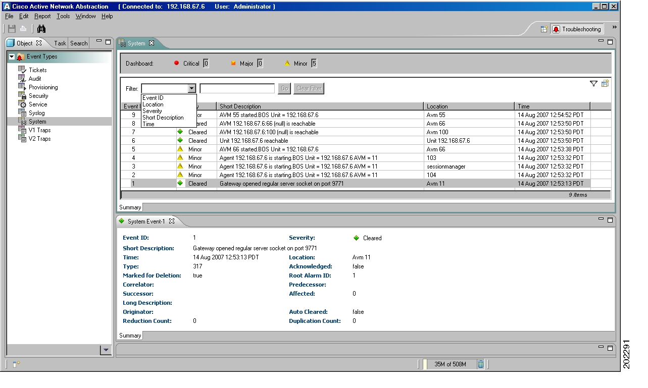
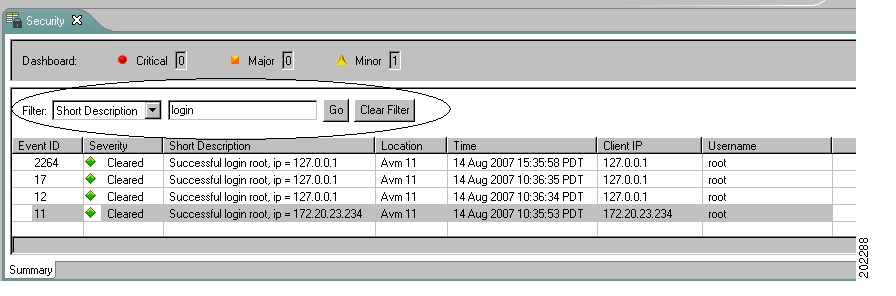
Simple Filter
Use the simple filter to refine any displayed data according to a single search rule. Figure 1-12 illustrates the results of filtering a list of Security events so that only the events that have the word "login" in the description are displayed. Results that do not meet the search criteria are removed. If you no longer want to apply any filtering, click Clear Filter.
Figure 1-12 Simple Filter
Note
Advanced Filter
The advanced filter has the same look and feel as the search tool (see Using Search). Use the advanced filter to customize results using multiple filter rules, or rules that offer more granularity (for example, rules that use operators such as does not contain or greater than). Figure 1-13 illustrates the same search criteria used in Figure 1-12. However, with the advanced filter you can add additional rules, such as filtering by username and location. Click Add and then OK to create the filter and view the results.
Note
Figure 1-13 Advanced Filter
Launching Online Help
The ANA online help system contains information on all installed features. The online help system is searchable and contains an index and printable manuals (in PDF format). You can launch the ANA online help in these ways:
•
•
The Workflow Editor also provides vendor-specific help. For information on how to launch the Workflow Editor vendor help, see Understanding the Workflow Editor User Interface, page B-4.
Customizing the UI
Eclipse provides many methods for changing the layout of the user interface. When you log in, your preferences are set to whatever was last saved on the server; in other words, preferences are saved on a per-machine basis rather than a per-user basis.
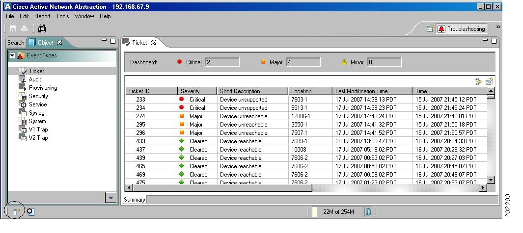
Fast views are commonly used to minimize views you do not want to see all the time. If a view or portion of the navigation disappears, most likely you changed it to a fast view by mistake. Figure 1-14 shows a Troubleshooting perspective with the Fast View icon (circled, under the navigation area). Note that the navigation area does not have a Tasks tab; the Tasks navigation area is a fast view, and can easily be activated by clicking the icon in the Fast View toolbar.
Note
Figure 1-14 Fast Views
To undo a fast view, select the Fast View icon and deselect Fast View.
You can always restore your perspective to its original layout at any time by choosing Window > Reset Perspective.
Note
![]()
![]()
![]()
![]()
![]()
![]()
![]()
![]()
Posted: Mon Sep 24 07:32:14 PDT 2007
All contents are Copyright © 1992--2007 Cisco Systems, Inc. All rights reserved.
Important Notices and Privacy Statement.