cc/td/doc/product/rtrmgmt/ana/4_0
hometocprevnextglossaryfeedbacksearchhelp
PDF

Table Of Contents

Customizing Network Element Information Using Soft Property Builder

What Are Soft Properties?

Alarm Thresholds

Understanding and Using the Soft Property Builder User Interface

Roles Required to Use the Soft Property Builder

Getting Started with Soft Properties

Viewing Existing Soft Properties

Creating or Editing a Soft Property

Defining the General Properties of a Soft Property

Defining the Parsing Rules for a Soft Property

Defining the Event Properties and Thresholds for a Soft Property (Property Type)

Viewing a Soft Property in the Inventory Window

Publishing a Soft Property

Deleting a Soft Property

Importing and Exporting a Soft Property

Examples

Basic Soft Property Example

Soft Property Example Including TCA Alarm

Soft Property Table Example

Parsing Operators and Rules

Alarm Threshold Triggers

Regular Expressions

Supported Syntax

Unsupported Syntax


Customizing Network Element Information Using Soft Property Builder


ANA maintains a live model of the network that is based on a network element component modeling architecture. In this architecture, each network element is modeled as an interconnected hierarchy of network element components, both physical (for example, cards, ports) and logical (for example, forwarding tables, profiles). Each network element component maintains a set of properties, which contain its actual data (status, configuration, performance, and so on).

When interacting with northbound clients, the network element component modeling information is translated internally into information model objects in Cisco's northbound information model. This is the public language of the ANA system with external systems.

The ANA property management framework enables you to extend (in runtime) the system's coverage and capabilities in two areas, namely:

Soft properties—Extending the network element data collection and modeling, by adding new properties to the network element components, and assigning them to network element MIB variables. The new soft properties are also automatically added to the northbound information model object.

Alarm thresholds—Assigning various types of alarm conditions to soft properties.

All property definitions and parameters are maintained in XML metadata in the registry. To ease the definition process, ANA provides a user interface called the Soft Property Builder, that guides you through the definition and testing process, and hides the underlying XML definitions.

The following topics explain how to use the Soft Property Builder to extend the network element data collection and modeling performed by ANA:

What Are Soft Properties?

Understanding and Using the Soft Property Builder User Interface

Roles Required to Use the Soft Property Builder

Getting Started with Soft Properties

Viewing Existing Soft Properties

Creating or Editing a Soft Property

Viewing a Soft Property in the Inventory Window

Publishing a Soft Property

Deleting a Soft Property

Importing and Exporting a Soft Property

Examples

Parsing Operators and Rules

Alarm Threshold Triggers

Regular Expressions

What Are Soft Properties?

ANA VNEs, by default, model a subset of the network element properties, which cover the most important and commonly used properties. ANA offers the soft properties mechanism to enable user-configurable extension of network element modeling, which can cover any unsupported MIB variable. This enables adding new monitored network element properties in runtime to the default set of supported properties.

The soft properties mechanism enables quick adaptation to new software upgrades and new requirements that arise during ongoing operation and deployment. It provides the field engineer with the ability to adapt the currently installed ANA software to changes in the deployed network.

Every soft property is implemented through a set of definitions that determine how to retrieve, parse, and display a certain MIB variable from the network element. The definition process is done through a user interface utility, and does not require system restart. Soft properties are retrieved from the network element using SNMP or Telnet/SSH.

For example, consider the case where the ANA system monitors the port parameters of an ATM switch, and the operator installs a new software version on the switch that is capable of reporting the bit error rate (BER) for each of the ports. Since this capability was not supported in previous software versions of the network element, the ANA VNE might not support the property. To avoid the need for a new VNE from Cisco, the soft property mechanism enables you to immediately support the new BER feature in the currently installed version.

Alarm Thresholds

ANA's main positioning is as a mediation layer between the network and the operational and business support systems. As such, it abstracts the physical network and provides a generic, vendor-neutral network model, with a consistent information model and interface.

ANA also enables you to leverage its live network model for intelligent data processing within the mediation layer. This enables ANA to conduct advanced processing in areas like fault correlation, root-cause analysis, impact analysis, activation design/validation, and so forth. This intelligence enables ANA to provide processed information to the network resource management features in the upper tiers. This enables ANA to enhance feature functionality, while dramatically reducing the feature's complexity and the uploaded data volumes.

Alarm thresholding is one of the major areas in which ANA can boost its northbound clients. With this mechanism, ANA constantly monitors selected properties and generates an alarm every time they cross a user-defined threshold or violate a condition. This eliminates the need for OSS/BSS applications to constantly upload huge amounts of data and process it. Instead, ANA filters out irrelevant data, and sends only meaningful notifications.

Understanding and Using the Soft Property Builder User Interface

This section provides instructions for launching the Soft Property Builder. The Soft Property Builder is launched in the Inventory perspective from a specific network element, which could be a managed element or a selected object within a managed element, such as a port. This network element is used to develop and test the soft property. The content displayed in the Soft Property Builder window is based on the location from which it is launched.

Once the soft property has been completed it can be published and attached to a wider scope of managed elements.


Note Initially the soft property only applies to the specific object that you are working on during runtime. Once the soft property has been published and the system has been restarted it is applied to all objects of the same type, according to the location to which it is published.


To open the Soft Property Builder:


Step 1 Go to the Objects tab in the Inventory perspective.

Step 2 Select a managed element in the navigation pane and right-click Soft Property Builder.

Step 3 Click the Add Soft Property button.

Step 4 Click one of the tools described in Figure A-1.


Figure A-1 provides an example of the Soft Property Builder main window.

Figure A-1 Soft Property Builder Window

The workflow below describes the steps required to define a new soft property definition using the Soft Property Builder, and the order in which they must be performed.

The following tool buttons are located in the Soft Property Builder toolbar.

Table A-1 Soft Property Builder Tool Buttons 

Icon
Description

Create a new soft property.

Edit an existing soft property.

Delete a published or unpublished soft property

Copy a soft property from an exported file and import the soft property to another managed element.

Save the soft property to a file that can later be imported to another managed element.

Move the soft property to a different location or change the scope of the soft property across the network hierarchy.


Roles Required to Use the Soft Property Builder

Table A-2 lists the roles that are required to use the Soft Property Builder. For more information on roles, see Creating and Managing Users and Scopes, page 14-27.

Table A-2 Roles Required to Use the Soft Property Builder 

Task
Role Required

Add a soft property

Configurator, Administrator

Edit an existing soft property

Configurator, Administrator

Delete an existing soft property

Configurator, Administrator

Import a soft property

Configurator, Administrator

Export a soft property

Configurator, Administrator

Publish a soft property

Configurator, Administrator


Getting Started with Soft Properties

These topics describe the soft property working environment and how to access the soft property tools. In addition, it describes the following steps showing how to create and publish a soft property:

Viewing Existing Soft Properties—Describes how to open the Soft Property Builder.

Creating or Editing a Soft Property—Describes how to start creating a soft property. In addition, it describes how to edit a soft property.

Defining the General Properties of a Soft Property—Describes how to define the general parameters of a soft property, including a soft property table.

Defining the Parsing Rules for a Soft Property—Describes how to define the parsing parameters of a soft property.

Defining the Event Properties and Thresholds for a Soft Property (Property Type)—Describes how to define the TCA alarms parameters of a soft property.

Viewing a Soft Property in the Inventory Window—Describes how to view the newly created or edited soft property in the Inventory window.

Publishing a Soft Property—Describes how to publish a soft property to one or more locations across the inheritance hierarchy.

Deleting a Soft Property—Describes how to delete a soft property.

Importing and Exporting a Soft Property—Describes how to export and import soft properties between managed elements.

Viewing Existing Soft Properties

As shown in Figure A-1, the Soft Property Builder window displays a table of all the existing soft properties according to the selected entity from which it has been launched. In addition, the applicable properties panels for the managed entity from which the Soft Property Builder was launched are displayed.

The content displayed in the element properties table changes according to the selection made in the properties panel. The following information is displayed in the element properties table of the Soft Property Builder window:

Label—The name of the property as displayed in the user interface, for example, Port Type.

Type—The soft property type, namely, Property or Table.

Polling—The polling group specified for the property, for example, system or status.

Enabled—Runs (true) or does not run (false) the command.

Command Line—The command execution, for this protocol, that should be sent to the network element to retrieve the property. This command can be either a Telnet/SSH command or an SNMP get for a specific OID.

Protocol—The protocol used to retrieve the information (SNMP/OID or Telnet/SSH).

Creating or Editing a Soft Property

The Soft Property Builder enables you to create or edit an existing soft property using the Add Soft Property tool. First you must determine the managed element or selected object in the network element to which the soft property should be added.

To create a soft property:


Step 1 Go to the Objects tab in the Inventory perspective.

Step 2 Select a managed element in the navigation pane and right-click Soft Property Builder. The Soft Property Builder window is displayed, listing all soft properties for that network element.

Step 3 Do one of the following:

To create a soft property, click the Add Soft Property icon.

To edit an existing soft property, click the Edit Soft Property icon. The hierarchy manager table is displayed.


Note If user-friendly VNE names exist in the schema, then the hierarchy manager table displays these user-friendly registry location names in the VNE Hierarchy Location column. A user-friendly VNE name is a hierarchy path that has been defined in the registry and is then displayed in the hierarchy manager table. For more information see Publishing a Soft Property.


Select the required version of the soft property from the hierarchy manager, and click OK.

Step 4 Specify the soft property configuration by working through the following configuration steps:

a. Define General Properties—Configures general definitions for the soft property. See Defining the General Properties of a Soft Property.

b. Set Parsing Rules—Configures parsing definitions for the soft property. See Defining the Parsing Rules for a Soft Property.

c. Event Creation—Configures alarm threshold management for the soft property. See Defining the Event Properties and Thresholds for a Soft Property (Property Type).


For information about viewing the edited soft property in the Inventory window, see Viewing a Soft Property in the Inventory Window.

For information about publishing the edited soft property, see Publishing a Soft Property.

Defining the General Properties of a Soft Property

Use the Define General Properties dialog box to configure general definitions for the soft property. You can also configure just a single soft property field or an entire soft property table.

To define the general properties:


Step 1 Open the Define General Properties dialog box as described in Creating or Editing a Soft Property. An example of the Define General Properties dialog box is in Figure A-2.

Figure A-2 Soft Property Define General Properties Dialog Box

Step 2 Configure the identification parameters:

Event Name—The soft property identifier, which is unique to the location and information model object scope.


Note A warning message is displayed if the name specified already exists. You are asked whether to override the existing soft property implementation.


Label—The soft property name that is displayed in the user interface, which is unique to the location and information model object scope.

Description—A description of the soft property.

Step 3 Configure the Protocol parameters:

Type—The soft property type, namely, Property or Table. By default, Property is selected. The fields displayed in the Parsing Rules dialog box depend on your selection. (The selection you make here determines the Protocol retrieval type.)

Polling Rate—The polling rate group to which the soft property is assigned to one of the following:

trapevent

topo_unicast_pkts

topo_I2

buffering

topo_I1

configuration

status

system

Protocol—Retrieve the information using the following protocol.

SNMP get to get a MIB OID—Selected when you choose Table as the soft property type.

Telnet/SSH command—Selected when you choose Property as the softy property type.

Sometimes, when building a soft property, the SNMP or Telnet command is context sensitive. For example, when you want to retrieve some port-related data through SNMP, checking all the ports each time to find the relevant port is not efficient and can greatly affect system performance. To solve this problem, instrumentation data is available for the soft property. The instrumentation data is a variant between different elements in the system, depending on the context object to which you want to add the soft property.

For example, if the instrumentation data is the port ifIndex, to use the ifIndex in the OID, use the following:

1.3.1.6......$ifIndex$.5.6.4

To determine which instrumentation data is available for your context object, place your cursor in the CLI/OID field and press Ctrl-Spacebar.

CLI/OID—The command line of the protocol:

For SNMP (Table), the OID of the packet (for SNMP, the OID of the packet; for Telnet, the Telnet command).


Note Start the SNMP OID with a dot. For example, if you want to retrieve the OID value of 1.3.6..., then write .1.3.6...


For Telnet (Property), the Telnet command.

Step 4 Make your selections in the Control area:

Enable this Soft Property—Enables or disables the VNE to run or not run the command. By default, this option is enabled.

Debug—Runs the command entered in the CLI/OID field, so you can view an example of the output.

Step 5 Do one of the following:

Click Next to save your settings and display the Set Parsing Rules dialog box. Proceed to one of the following sections, depending on the type of soft property you are creating:

For a Property type soft property, see Defining the Parsing Parameters for a Soft Property (Property Type).

For a Table type soft property, see Defining the Expressions of a Soft Property Table.

Click Cancel to close the Add Soft Property dialog box without saving any changes.


Defining the Parsing Rules for a Soft Property

Use the Set Parsing Rules dialog box to configure, view, and edit parsing definitions defined for the soft property. The rules you must set depend on the type of soft property you are creating or editing:

For a Property type soft property, see Defining the Parsing Parameters for a Soft Property (Property Type).

For a Table type soft property, see Defining the Expressions of a Soft Property Table.

Defining the Parsing Parameters for a Soft Property (Property Type)

To define the parsing parameters for a soft property of the type Property:


Step 1 Open the Set Parsing Rules dialog box after defining the general parameters as described in Defining the General Properties of a Soft Property. An example of the Set Parsing Rules dialog box is in Figure A-3.

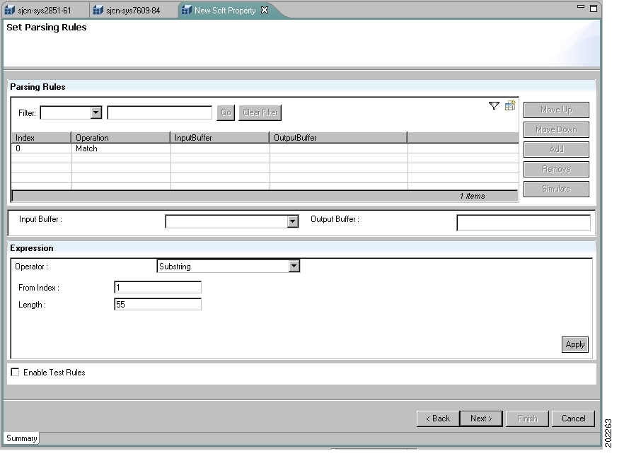
Figure A-3 Soft Property Set Parsing Rules Dialog Box

The Set Parsing Rules dialog box has two major areas:

Parsing Rules area—Lists your parsing rules once you have defined them and have clicked Apply in Expressions. The table lists the following information on configured rules:

Index—Order of the parsing rules.

Operation—Parsing operator type for a rule.

InputBuffer—Input arguments defined for a parsing rule.

OutputBuffer—Output arguments defined for a parsing rule.

Expressions—Where you define your parsing rules. This area is activated by clicking the Add button in the Parsing Rules area.

Step 2 In the Parsing Rules area, click Add to indicate that you want to add a parsing rule. ANA activates the choices in Expressions.

Step 3 In Expressions, define a parsing rule:

a. Select a parsing operator from the dropdown list:

Header And Footer—Removes a specified number of lines from the header and footer of the input text. For more information see Header and Footer.

Remove Lines—Removes a range of lines from the specified starting row to the specified end row of the input text. For more information see Remove Lines.

Select Lines—Extracts a range of lines from the specified starting row to the specified end row of the input text. For more information see Select Lines.

Replace—Finds one or all occurrences of a substring that matches a specified regular expression, and replaces it with a specified value. For more information see Replace.

Match—Finds and extracts a substring that matches a specified regular expression. If no match can be found, the output buffer receives an empty string. For more information see Match.

Set—Formats the input buffer and local arguments defined in previous operators using a regular expression. For more information see Set.

Substring—Extracts a substring of a specified length from a specified starting point. For more information see Substring.

Parse Integer—Uses the substring rule; when a result is received with the substring; the substring is converted into an integer value. For more information see Parse Integer.


Note If the substring operator contains any special characters the parsing integer operator fails.


b. Click Apply. The rule is added to the Parsing Rules table.

c. If desired, select the input and output buffers:

Input Buffer—A dropdown list that displays the output arguments defined in previous operators and the default (the standard output buffer of the last predecessor operator that was not redirected into an output argument).

The parsing result of operator N is available by default as input for operator N+1 (appears as Default for the Input Buffer). The parsing result of operator N may be directed to a locally defined environment argument. In this case the input for operator N+1 is the same as for operator N. Changing the default input buffer is supported by selecting an input buffer other than Default. The available input buffers for operator N+1 consist of the set of output arguments defined in operators 1 through N.

The Direct result to output buffer variable checkbox and corresponding field enables you to direct the parsing output to the provided argument instead of making it the input value for the next operator. The text box is enabled only when the checkbox is checked. A unique (within the complete parsing sequence of this soft property instance) argument name must be provided in this field.

d. If desired, configure additional parsing rules.

Step 4 Review the Parsing Rules table and use the following buttons as needed (click in the table to activate the buttons):

Move Up—Moves an operator up in the parsing order sequence.

Move Down—Moves an operator down in the parsing order sequence.

Add—Adds a new operator and re-activates the other buttons.

Remove—Deletes the selected operator from the table.

Simulate—Tests a selected soft property parsing (highlight the rule you want to test).

Step 5 Check Enable Test Rules if you want to test all of the parsing rules after you have finished configuring them. This activates the Test Rules dialog box in Step 7. If you do not check this option, the Test Rules dialog is not displayed.

Step 6 If you checked Enable Test Rules in Step 5, the Test Rules dialog opens.

a. In the Input Buffer area, enter the input to parse. The parsing input can be copied and pasted by you or be retrieved from the network element.

b. Click Test. The Output Buffer area displays the parsing result log. It may contain only the final parsing result or the entire parsing log with comments per parser used.

Step 7 Click Next to open the Event Creation dialog box. Proceed to Defining the Event Properties and Thresholds for a Soft Property (Property Type).


Defining the Expressions of a Soft Property Table

The parameters you enter here determines what new information is displayed when you select a network element in the Inventory perspective.

To define the parsing parameters:


Step 1 Open the Set Parsing Rules dialog box after defining the general parameters (as described in Defining the General Properties of a Soft Property). Go to Expressions.

Expressions—Where you define your rules. This area is activated by clicking the Add button in the Parsing Rules area.

Table area—Where you define the soft property table information you want to retrieve.

Title—Column heading of the new table.

OID—SNMP get command information.

Step 2 Click Finish.


Defining the Event Properties and Thresholds for a Soft Property (Property Type)

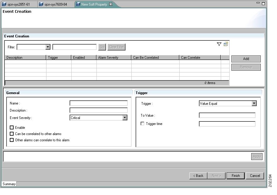
Use the Event Creation dialog box to set threshold conditions for the soft property value, which generates an alarm when crossed. This is only valid if you have selected a soft property of the type Property. You can select the following:

Severity level that is associated with the alarm.

Enable/disable the alarm.

Select the threshold type.

Define multiple alarms for the same soft property.

When the alarm is generated, it is displayed in the Tickets table in the Troubleshooting perspective.

To define the Event Properties parameters:


Step 1 Open the Event Creation dialog box after defining the parsing rules as described in Defining the Parsing Parameters for a Soft Property (Property Type). An example of the Define General Properties dialog box is in Figure A-4.

Figure A-4 Soft Property Set Parsing Rules Dialog Box

The Event Creation dialog box has three major areas:

Event Creation—Lists your events once you have defined them and click Apply. The table lists the following information on configured rules:

Description—Alarm description.

Trigger—Alarm threshold trigger.

Enabled—Whether alarm is enabled or disabled.

Alarm Severity—Severity level.

Can Be Correlated—Whether the alarm can be correlated to another alarm.

Can Correlate—Whether the alarm can correlate to other alarms.

General—Where you define the event name, description, severity, correlation settings, and enable/disable settings.

Trigger—Where you define the threshold that generates the alarm.

Step 2 Configure the General parameters:

Name—The alarm name that is displayed in the ticket pane when the alarm is triggered.

Description—A description of the alarm.

Alarm Severity—Select the severity level associated with the alarm, namely:

Critical

Major

Minor

Warning

Normal

Enabled—Check or uncheck this box to enable or disable the alarm.

Can be correlated to other alarms—Check this box to correlate this alarm to other alarms.

Other alarms can correlate to this alarm—Check this box to enable other alarms to be correlated to this alarm.

Step 3 Configure the Trigger parameters:

Trigger—Select one of the following threshold types:

Value Equal—The alarm condition is reached when the soft property value is equal to the value defined in Alarm Value, regardless or whether or not it is numeric. For more information see Value Equal.

Value Not Equal—The alarm condition is reached when the soft property value is not equal to the value defined in Alarm Value, regardless of whether or not it is numeric. For more information see Value Not Equal.

Upper Threshold—The upper threshold value, which, when crossed, triggers the alarm for the defined numeric properties. For more information see Upper Threshold.

Lower Threshold—The lower threshold value, which, when crossed, triggers the alarm for the defined numeric properties. For more information see Lower Threshold.

Upper Rate—The upper rate threshold value for the performance counters, which, when crossed, triggers the alarm for the defined numeric properties. For more information see Upper Rate.

Lower Rate—The lower rate threshold value for the performance counters, which when crossed triggers the alarm for the defined numeric properties. For more information see Lower Rate.

To Value—The value that, when reached, generates the alarm.

Trigger Time—Check this box if you want to trigger the alarm after the threshold has been exceeded for a certain amount of time. Enter the time in seconds.

Step 4 Click Apply. The event is added to the Event Creation table.

Step 5 Review the Event Creation table and use the following buttons as needed:

Add—Adds the event to the table and allows you to keep creating new events.

Remove—Deletes the selected event from the table.

Step 6 Click Finish. After 5-10 seconds, the information is added to the properties information in the Inventory perspective.


Viewing a Soft Property in the Inventory Window

After creating or editing a soft property you can view the results by double-clicking the network element in the Inventory perspective.


Note You are only able to view the soft property in the perspective after waiting 5-10 seconds and then closing and reopening the information. For example, if you open an inventory on a VNE and add a property to one of the ports, then it is only displayed after you close and reopen the inventory on the VNE.


To view the soft property:


Step 1 Double-click on the required managed element in the tree pane or workspace of the ANA window. The inventory information for the required managed element is displayed with the newly defined soft property or soft property table.

Step 2 Click in the top right corner to close the Inventory window.


Proceed to Publishing a Soft Property to publish the soft property.

Publishing a Soft Property

A property definition is applicable to all objects of the same type in a selected network element. However, you may want to apply the same property definitions to all network elements of the same type or family. This requires moving the property definition from the specific network element instance to a higher level in the registry hierarchy. This is controlled by the hierarchy manager.

After the soft property has been defined and tested on a specific instance of a managed element, it can be published and applied to a wider scope of managed elements in the network.

The Soft Properties Publish Controller dialog box enables you to publish the soft property to one or more locations across the inheritance hierarchy (as defined in the system). In other words, you defines the scope where the soft property is applied in the hierarchy.

Different variations of a soft property can be used for different managed elements and network elements, where the implementation of the soft property is different for each managed element or network element.

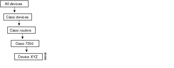
An example of an inheritance hierarchy is displayed below. In this example, the top level of the hierarchy is All network elements and the lowest level of the hierarchy is Device XYZ.

Figure A-5 Inheritance Hierarchy Example

When a soft property is published to a node in the hierarchy, this overrides any inherited soft properties from a higher level, and automatically applies it to all its children. For example, if a soft property is published to Cisco 7200 it overrides any variant of this soft property, which is defined at a higher level, and is assigned to all devices of the type Cisco 7200 in the system.


Note It is highly recommended that before you publish the soft property, you measure its effect on system memory usage. For more information on measuring the effect of publishing a soft property, contact ask-ana@cisco.com.


To publish a soft property:


Step 1 Go to the Objects tab in the Inventory perspective.

Step 2 Select a managed element in the navigation pane and click the Add Soft Property button.

Step 3 Click the Publish Soft Property icon. The hierarchy manager table is generated and displayed.


Note If user-friendly VNE names exist in the schema, then the hierarchy manager table displays them in the VNE Hierarchy Location column. A user-friendly VNE name is a hierarchy path that has been defined in the registry and is then displayed in the hierarchy manager table. For more information see Publishing a Soft Property.


Each row that is displayed in the hierarchy manager table represents a different level of the hierarchy. The rows are displayed in descending order; the top row is the highest level of the hierarchy and the bottom row is the lowest level of the hierarchy.

The following information is displayed in the table:

Exist—When a node in the hierarchy is selected, this indicates that a local variant of the soft property exists for that node.

VNE Hierarchy Location—The hierarchy path, as defined in the registry.

IMO Class Name—Information model object class name, currently unavailable in this version.

The following tools are displayed in the Hierarchy Manager window:

Table A-3 Hierarchy Manager Tool Buttons 

Icon
Description

Copies the soft property from a selected node in the hierarchy to copy it to another node in the hierarchy. A copy icon is displayed to the left of the selected node.

Cuts the soft property from a selected node in the hierarchy to move it to another node in the hierarchy. A cut icon is displayed to the left of the selected node.

Pastes the soft property that was copied or cut from a selected node in the hierarchy to another node in the hierarchy. A paste icon is displayed to the left of the selected node.

Deletes the soft property from the selected node in the hierarchy.

Note If the soft property has been deleted from all the nodes, the soft property is removed from the list in the main dialog of the Soft Property Builder.

Exports the soft property to a file, so it can be imported to different nodes.

Imports a published soft property file, so it can be applied to different nodes.


The following button is displayed in the Hierarchy Manager window:

Close—Closes the Hierarchy Manager window without publishing the soft property.

Step 4 Select the required node in the hierarchy from which you want to publish the soft property.

Step 5 Click Copy or Cut on the toolbar to copy or cut the soft property.

Step 6 Select the required node in the hierarchy where you want to publish the soft property.

Step 7 Click Paste on the toolbar to paste the soft property. The soft property is published to the selected node in the hierarchy.


Deleting a Soft Property

Soft properties that you create are, by default, always created as a local instance. A soft property that is defined locally is selected in the Soft Properties Publish Controller dialog box. You can delete soft properties whether or not they have been published.

To delete a soft property:


Step 1 Go to the Objects tab in the Inventory perspective.

Step 2 Select a managed element in the navigation pane and click the Add Soft Property button.

Step 3 Click the Delete Soft Property icon. A warning message is displayed.

Step 4 Click Yes. The soft property is deleted and no longer displayed in the element properties table of the Soft Property Builder window.


Importing and Exporting a Soft Property

The Soft Property Builder enables you to export (save) a soft property definition to a file. The soft property definition can then be imported (copied) later to another managed element. In addition, you can export and import a soft property definition to a file and publish it to multiple places in the Hierarchy Manager window.

To export a soft property:


Step 1 Go to the Objects tab in the Inventory perspective.

Step 2 Select a managed element in the navigation pane and click the Add Soft Property button.

Step 3 Click the Export Soft Property icon. The Export Elements dialog box is displayed.


Note If user-friendly VNE names exist in the schema, then the hierarchy manager table displays them in the VNE Hierarchy Location column. A user-friendly VNE name is a hierarchy path that has been defined in the registry and is then displayed in the hierarchy manager table. For more information see Publishing a Soft Property.


Step 4 Select the version that you want to export in the table of the Export window. The version is selected in the table.

Step 5 Click OK. A directory browser window opens.

Step 6 Browse to the directory where you want to save the soft property.

Step 7 In the File name field, enter a name and extension (for example, .txt) for the soft property.

Step 8 Click Save. The soft property is saved in the selected directory. The Export dialog box is displayed.

Step 9 Click Close. The Soft Property Builder window is displayed.


To import a soft property:


Step 1 Go to the Objects tab in the Inventory perspective.

Step 2 Select a managed element in the navigation pane and click the Add Soft Property button.

Step 3 Click the Export Soft Property icon. The Import Element dialog box is displayed.

Step 4 Browse to the directory and soft property that you want to import.

Step 5 Click Open. The Import elements window is displayed.

Step 6 Select the version that you want to import in the table of the Import Elements window. The version is selected in the table.

Step 7 Click OK. The Soft Property Builder window is displayed.

Step 8 Click Close. The soft property is imported to the selected managed element or network element and displayed in the Soft Property Builder window.


Examples

These topics provide several examples of creating a soft property from start to finish, including defining the TCA alarms and defining a soft property table:

Basic Soft Property ExampleDescribes how to create a simple soft property from beginning to end, including publishing the soft property to another node in the hierarchy.

Soft Property Example Including TCA Alarm—Describes how to define a TCA alarm for a soft property.

Soft Property Table Example—Describes how to define a soft property table.

Basic Soft Property Example

This section describes how to create a simple soft property from beginning to end.

To create a soft property (without a TCA alarm):


Step 1 Go to the Objects tab in the Inventory perspective.

Step 2 Select a managed element in the navigation pane and right-click Soft Property Builder. The Soft Property Builder window is displayed, listing all soft properties for that network element.

Step 3 Configure the Identification parameters:

Event Name—sp01

Label—My Soft Property

Description—Example of soft property

Step 4 Configure the Protocol parameters:

Type—Property

Polling Rate—Status

Protocol—Use Telnet/SSH

CLI/OID—show ip vrf example

Step 5 In the Control area, select Enable this Soft Property.

Step 6 Click Next to save your settings and display the Set Parsing Rules dialog box.

Step 7 In the Parsing Rules area, click Add to indicate you want to add a parsing rule. ANA activates the choices in Expressions.

Step 8 In Expressions, define a parsing operator from the dropdown list:

Operator—Match

Expression—\d\d

Source text box—Enter the information as shown in the example.

Step 9 Click Apply. The rule is added to the Parsing Rules table.

Step 10 Highlight the rule and click Simulate. The result 55 is displayed in the Result text box.

Step 11 In the Parsing Rules area, click Add to indicate you want to add another parsing rule. ANA activates the choices in Expressions.

Step 12 Define the information in Expressions:

Operator—Substring

From Index—1

To Index—1

Source text box—55

Step 13 Click Apply. The rule is added to the Parsing Rules table.

Step 14 Highlight the rule and click Simulate. The result 5 is displayed in the Result text box.

Step 15 Select Enable Test Rules (to test all of the parsing rules after you have finished configuring them) and click Next.

Step 16 In the Input Buffer area, enter the input to parse. This is the text or content you want to simulate for the selected rule.

Step 17 Click Test. The Output Buffer area displays the parsing result log. It may contain only the final parsing result or the entire parsing log with comments per parser used.

Step 18 Click Finish. To view the newly created soft property, click in the right top corner to close the Inventory perspective and then open the Inventory perspective again.

Step 19 Right-click on the managed element and select Soft Property Builder.

Step 20 Click Publish Soft Property on the toolbar of the Soft Property Builder dialog box. The Hierarchy Builder window is displayed.

Step 21 Select the required node in the hierarchy from which you want to publish the soft property.

Step 22 Click Copy or Cut on the toolbar to copy or cut the soft property.

Step 23 Select the required node in the hierarchy where you want to publish the soft property.

Step 24 Click Paste on the toolbar to paste the soft property. The soft property is published to the selected node in the hierarchy.

Step 25 Click Close. The Soft Property Builder window is displayed.


For more information about defining a soft property with a TCA alarm, see Soft Property Example Including TCA Alarm.

Soft Property Example Including TCA Alarm

This section describes how to define a TCA alarm for a soft property.

To create a soft property including TCA alarm:


Step 1 Perform steps 1- 17, as described in the Basic Soft Property Example.

Step 2 Click Next to open the Event Creation dialog box.

Step 3 Configure the General parameters:

Name—My value is not 5.

Description—Show this alarm if the value is not equal to 5.

Alarm Severity—CRITICAL.

Enabled—Selected.

Step 4 Configure the Trigger parameters:

Trigger—Value Not Equal.

To value—5

Step 5 Click Apply. The event is added to the Event Creation table.

Step 6 Review the Event Creation table and use the following buttons as needed:

Add—Adds the event to the table and allows you to continue creating new events.

Remove—Deletes the selected event from the table.

Step 7 Click Finish. The soft property is added to the Soft Property Builder table.

Step 8 To view the newly created soft property, click in the right top corner to close the Inventory perspective and then open the Inventory perspective again.

Step 9 Perform steps 19- 25, as described in Basic Soft Property Example.


For more information about defining a soft property table, see Soft Property Table Example.

Soft Property Table Example

To create a soft property table:


Step 1 Go to the Objects tab in the Inventory perspective.

Step 2 Select a managed element in the navigation pane and right-click Soft Property Builder.

The Soft Property Builder window is displayed, listing all soft properties for that network element.

Step 3 Configure the Identification parameters:

Name—sp02

Label—My Soft Table

Description—Example of a soft table

Step 4 Configure the Protocol parameters:

Type—Table

Polling Rate—Status

Protocol—SNMP

CLI/OID—.1.3.6.1.2.1.4.20.1

Step 5 In the Control area, select Enable this Soft Property.

Step 6 Click Next to save your settings and display the Set Parsing Rules dialog box.

Step 7 In the Parsing Rules area, click Add to indicate you want to add a parsing rule. ANA activates the choices in Expressions.

Step 8 In Expressions, define a parsing operator from the dropdown list:

Column Title—My First Column

Column Data—2

Step 9 Click Apply. The rule is added to the Parsing Rules table.

Step 10 In the Parsing Rules area, click Add to indicate you want to add another parsing rule. ANA activates the choices in Expressions.

Step 11 Define the information in Expressions:

Column Title—My Second Column

Column Data—3

Step 12 Click Apply. The rule is added to the Parsing Rules table.

Step 13 Click Finish.

Step 14 To view the newly created soft property, double-click on the network element.

Step 15 Perform steps 19- 25, as described in Basic Soft Property Example.


Parsing Operators and Rules

These topics describe the pre-defined text manipulation operators available for parsing raw network element input and turning it into a soft property that is available in the Add/Edit Parsing Rule dialog box. For each operator, its name, description, expected input, validation rules, and unique fields displayed in the dialog box are described. An example of each operator is also provided.

For more information about the Add/Edit Parsing Rule dialog box, see Defining the Parsing Rules for a Soft Property.

Header and Footer—Describes the Header And Footer operator and provides an example.

Remove Lines—Describes the Remove Lines operator and provides an example.

Select Lines—Describes the Select Lines operator and provides an example.

Replace—Describes the Replace operator and provides an example.

Match—Describes the Match operator and provides an example.

Set—Describes the Set operator and provides an example.

Substring—Describes the Substring operator and provides an example.

Parse Integer—Describes the Parse Integer operator and provides an example.

Header and Footer

Header and Footer removes a specified number of lines from the header and footer of the input text.

Parameter
Description
Validation Rule

Header lines

The number of header lines to be removed.

Integers only. Mandatory.

Footer lines

The number of footer lines to be removed.

Integers only. Mandatory.


Remove Lines

Remove Lines removes a range of lines from the specified starting row to the specified ending row of the input text.

Parameter
Description
Validation Rule

From line

Index of first row to begin removal, inclusive.

Integer only. Mandatory.

To line

Index of last row to be removed, inclusive.

Integer only. Equal to or greater than From line. Mandatory.


Select Lines

Select Lines extracts a range of lines from the specified starting row to the specified ending row of the input text.

Parameter
Description
Validation Rule

From line

Index of first row to begin selection, inclusive.

Integer only. Mandatory.

To line

Index of last row to be selected, inclusive.

Integer only. Equal to or greater than From line. Mandatory.


Replace

Replace finds one or all occurrences of a substring, that matches a specified regular expression, and replaces it with a specified value.

Parameter
Description
Validation Rule

Expression

Search for value or regular expression.

Text. Mandatory.

With

Replace string with value or regular expression.

Text. Mandatory.

From Index

Starting index.

Integer. Mandatory.

Note The value entered in this field must be 1 or higher.

Replace All

Checkbox. Check this option to replace all occurrences of the matching substrings; otherwise only the first instance is replaced.

Default is disabled.


Match

Match finds and extracts a substring, that matches a specified regular expression. If no match can be found, the output buffer receives an empty string.

Parameter
Description
Validation Rule

Expression

Search for value or regular expression.

Text. Mandatory.


Set

Set prints the results of the input and output buffers.

Parameter
Description
Validation Rule

Expression

Regular expression template to use for formatting. $_$ specifies the main output buffer.

Text. Mandatory.


Substring

Substring extracts a substring of a specified length from a specified starting point.

Parameter
Description
Validation Rule

From Index

Begin index to select.

Integer. Mandatory

Note The value entered in this field must be 1 or higher.

Length

How many characters to select.

Integer. Mandatory


Parse Integer

Parse Integer uses the substring rule, and when a result is received with the substring it is converted into an integer value.


Note If the substring operator contains any characters, the parsing integer operator fails.


The Add/Edit Parsing Rule dialog box is displayed below when the Parse Integer operator is selected. In addition, the dialog box displays an example using the Parse Integer operator.

Parameter
Description
Validation Rule

From Index

Starting index to select.

Integer. Mandatory

Note The value entered in this field must be 1 or higher.

To Index

Ending index to select.

Integer. Mandatory


Alarm Threshold Triggers

These topics describe the pre-defined alarm threshold triggers available for defining TCA alarms that are displayed in the Event Creation dialog box. For each alarm threshold trigger, its name, description, and the unique fields displayed in the dialog box are described. You can define multiple alarms for the same soft property. The alarm is displayed in the ticket pane of the Inventory perspective. A counter value, as described in these topics, is a numeric value that always increases. For more information about the Add TCA dialog box see Defining the Event Properties and Thresholds for a Soft Property (Property Type).

The following are the pre-defined alarm threshold triggers for defining TCA alarms:

Value Equal

Value Not Equal

Upper Threshold

Lower Threshold

Upper Rate

Lower Rate

Value Equal

The alarm condition is reached when the soft property value is equal to the value defined in the "Alarm Value" regardless if it is numeric or not.

The following fields are displayed when the Value Equal threshold type is selected:

To value—The target value.

Trigger alarm only if change persists more than—Select this option to trigger the alarm if the alarm criteria persist for the defined period. The time period is defined in milliseconds in the trigger alarm field. For example, if CPU usage is over 85% (the alarm criteria) and this persists for more than one minute (the defined period), then the alarm is triggered. Considering that the soft property polls the network element every x seconds, if the defined period is less than x, this is meaningless.

Value Not Equal

The alarm condition is reached when the soft property value is not equal to the value defined in the "Alarm Value" regardless if it is numeric or not.

The following fields are displayed when the Value Not Equal threshold type is selected:

To value—The target value.

Trigger alarm only if change persists more than—Select this option to trigger the alarm if the alarm criteria persist for the defined period. The time period is defined in milliseconds in the trigger alarm field.

Upper Threshold

The upper threshold value, which when crossed triggers the alarm for the defined numeric properties.

This threshold trigger must receive a numeric value. To receive a numeric value the parse integer rule must be applied on the soft property as an ending rule. For more information about parsing integers see Parsing Operators and Rules.

The following fields are displayed when the Upper Threshold type is selected:

Trigger alarm when value is above—The value which when crossed generates the alarm.

Clear alarm when value is below—The value which when crossed (when going back) clears the alarm.

Trigger alarm only if change persists more than—Select this option to trigger the alarm if the alarm criteria persist for the defined period. The time period is defined in milliseconds in the trigger alarm field.

Lower Threshold

The lower threshold value, which when crossed triggers the alarm for the defined numeric properties.

This threshold trigger must receive a numeric value. To receive a numeric value the parse integer rule must be applied on the soft property as an ending rule. For more information about parsing integers see Parsing Operators and Rules.

The following fields are displayed when the Lower Threshold type is selected:

Trigger alarm when value is below—The value which when crossed generates the alarm.

Clear alarm when value is above—The value which when crossed (when going back) clears the alarm.

Trigger alarm only if change persists more than—Select this option to trigger the alarm if the alarm criteria persist for the defined period. The time period is defined in milliseconds in the trigger alarm field.

Upper Rate

The upper rate trigger is used for checking the counter value changes over a period of one second. When the specified rate is crossed it triggers the alarm for the defined numeric property. When this is used with the Trigger alarm, described in Upper Threshold, you can check that the rate is maintained above the specified value over time.


Note The calculation for the "rate every one second" is as follows: if the property is sampled every x seconds, the calculation is the current value less the previous value divided by x seconds.


This threshold trigger must receive a numeric value. To receive a numeric value, the parse integer rule must be applied on the soft property as an ending rule. For more information about parsing integers see Parsing Operators and Rules.

The following fields are displayed when the Upper Rate threshold type is selected:

Trigger alarm when value is above—The value which when crossed generates the alarm.

Clear alarm when value is below—The value which when crossed (when going back) clears the alarm.

Trigger alarm only if change persists more than—Select this option to trigger the alarm if the alarm criteria persist for the defined period. The time period is defined in milliseconds in the trigger alarm field.

Lower Rate

The lower rate trigger is used for checking the counter value changes over a period of one second. When the specified rate is crossed, it triggers the alarm for the defined numeric property. When this is used with the Trigger alarm, described in Upper Threshold, you can check that the rate is maintained below the specified value over time.


Note The calculation for the "rate every one second" is as follows: if the property is sampled every x seconds, the calculation is the current value less the previous value divided by x seconds.


This threshold trigger must receive a numeric value. To receive a numeric value, the parse integer rule must be applied on the soft property as an ending rule. For more information about parsing integers see Parsing Operators and Rules.

The following fields are displayed when the Lower Rate threshold type is selected:

Trigger alarm when value is below—The value which when crossed generates the alarm.

Clear alarm when value is above—The value which when crossed (when going back) clears the alarm.

Trigger alarm only if change persists more than—Select this option to trigger the alarm if the alarm criteria persist for the defined period. The time period is defined in milliseconds in the trigger alarm field.

Regular Expressions

This section is based on the documentation of the package GNU RegExp.

A regular expression consists of a character string where some characters are given special meaning with regard to pattern matching. Regular expressions have been in use from the early days of computing, and provide a powerful and efficient way to parse, interpret, and search and replace text within an application.

See these topics for details about regular expressions:

Supported Syntax

Unsupported Syntax

Supported Syntax

Within a regular expression, the following characters have special meaning.

Positional Operators

^

Matches at the beginning of a line

$

Matches at the end of a line

\A

Matches the start of the entire string

\Z

Matches the end of the entire string

\b

Matches at a word break (Perl5 syntax only)

\B

Matches at a nonword break (opposite of \b) (Perl5 syntax only)

\<

Matches at the start of a word (egrep syntax only)

\>

Matches at the end of a word (egrep syntax only)


One-Character Operators

.

Matches any single character

\d

Matches any decimal digit

\D

Matches any nondigit

\n

Matches a newline character

\r

Matches a return character

\s

Matches any whitespace character

\S

Matches any nonwhitespace character

\t

Matches a horizontal tab character

\w

Matches any word (alphanumeric) character

\W

Matches any nonword (alphanumeric) character

\x

Matches the character x, if x is not one of the above listed escape sequences


Character Class Operators

[abc]

Matches any character in the set a, b or c

[^abc]

Matches any character not in the set a, b or c

[a-z]

Matches any character in the range a to z, inclusive

Leading or
trailing dash

Interpreted literally


Within a character class expression, the following sequences have special meaning if the syntax bit RE_CHAR_CLASSES is enabled:

[:alnum:]

Any alphanumeric character

[:alpha:]

Any alphabetical character

[:blank:]

A space or horizontal tab

[:cntrl:]

A control character

[:digit:]

A decimal digit

[:graph:]

A nonspace, noncontrol character

[:lower:]

A lowercase letter

[:print:]

Same as graph, but also space and tab

[:punct:]

A punctuation character

[:space:]

Any whitespace character, including newline and return

[:upper:]

An uppercase letter

[:xdigit:]

A valid hexadecimal digit


Subexpressions and Backreferences

(abc)

Matches whatever the expression abc would match, and saves it as a subexpression. Also used for grouping

(?:...)

Pure grouping operator; does not save contents

(?#...)

Embedded comment; ignored by engine

\n

Where 0 < n < 10, matches the same thing the nth subexpression matched


Branching (Alternation) Operator

a|b

Matches whatever the expression a or b would match


Repeating Operators

These symbols operate on the previous atomic expression.

?

Matches the preceding expression or the null string

*

Matches the null string or any number of repetitions of the preceding expression

+

Matches one or more repetitions of the preceding expression

{m}

Matches exactly m repetitions of the one-character expression

{m,n}

Matches between m and n repetitions of the preceding expression, inclusive

{m,}

Matches m or more repetitions of the preceding expression


Stingy (Minimal) Matching

If a repeating operator (above) is immediately followed by a question mark (?), the repeating operator stops at the smallest number of repetitions that can complete the rest of the match.

Lookahead

Lookahead refers to the ability to match part of an expression without consuming any of the input text. There are two variations to this:

(?=foo)

Matches at any position where foo would match, but does not consume any characters of the input

(?!foo)

Matches at any position where foo would not match, but does not consume any characters of the input


Unsupported Syntax

Some flavors of regular expression utilities support additional escape sequences. The following is not meant to be an exhaustive list. In the future, gnu.regexp may support some or all of the following:

(?mods)

Inlined compilation/execution modifiers (Perl5)

\G

End of previous match (Perl5)

[.symbol.]

Collating symbol in class expression (POSIX)

[=class=]

Equivalence class in class expression (POSIX)

s/foo/bar/

Style expressions as in sed and awk


hometocprevnextglossaryfeedbacksearchhelp

Posted: Mon Sep 24 07:33:48 PDT 2007
All contents are Copyright © 1992--2007 Cisco Systems, Inc. All rights reserved.
Important Notices and Privacy Statement.