|
|

Table Of Contents
Viewing Network Element States and Inventory
Understanding Network Element States
Changing the Network Element State from the Inventory Perspective
Viewing the Network Element Inventory
Viewing Network Element Properties
Viewing Physical Inventory Properties
Viewing Logical Inventory Properties
Viewing Network Element States and Inventory
This section describes the various network element states that are supported in ANA. It also provides information on how to view the physical and logical inventory for a selected network element.
•
Understanding Network Element States
•
•
Understanding Network Element States
Based on the results of inventory collection, network elements are moved to the appropriate states in ANA.
When you use the network element selector, you can see that the network elements that have been added to ANA are grouped based on the network element state and UMDF. See Using the Device Selector, page 1-15 for information on UMDF.
Table 3-1 lists the network element states in ANA.
Changing the Network Element State from the Inventory Perspective
You can change the state of a network element in the following ways:
•
•
You can change any of the network element states to one of the following:
•
•
•
Roles Required to Change a Network Element State
Table 3-2 lists the roles that are required to change a network element state. For more information on roles, see Creating and Managing Users and Scopes, page 14-27.
To change the network element state from the Inventory perspective:
Step 1
Step 2
•
•
•
Step 3
Viewing the Network Element Inventory
This section describes how to view the physical and logical inventories of a selected network element.
ANA maintains a continuous, real-time discovery of all the physical and logical entities of the network inventory and the relationships among them. It automatically reflects every addition, deletion, and modification that occurs in the network in its distributed system inventory.
The physical and logical inventory collection depends on the polling interval that you have specified while adding the network element. See Managing Polling Groups, page 14-4, for information on defining the polling interval.
The collection happens only for the network elements that are in managed state. You can view the physical and logical inventory for the network elements that are moved from managed state to maintenance state.
See the following to view the network element properties:
•
•
•
Viewing Network Elements
The Device drawer is available from the Object tab of the Inventory Perspective. This tab lists all of the network elements that are available in the ANA server. You can view all of the network elements based on either the UMDF grouping or the ANA network element states.
See Understanding Network Element States for information on UMDF and ANA network element states.
You can perform the following tasks by selecting a network element in the Device drawer:
•
•
•
•
•
•
•
•
•
Viewing Network Element Properties
To view the network element properties:
Step 1
Step 2
Or
Double-click the network element.
The network element properties are displayed in the workspace.
If the Properties view is enabled, the network element properties are displayed there. If you have disabled the Properties view, you can enable it using Window > Show View > Properties.
The following network element properties are displayed:
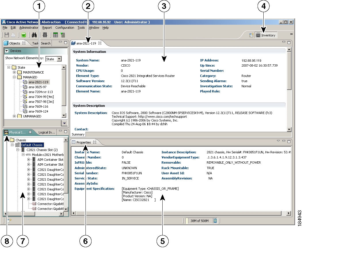
Viewing Physical Inventory Properties
The physical inventory reflects the physical components of the managed network element. The Physical Inventory tab displays a hierarchical (tree) view of the physical inventory, which might include chassis, modules, shelves, slots, subslots, ports, and so on for the selected network element in the Device drawer.
The Physical inventory is continuously updated for both status and configuration polling groups. The addition of a new card, the removal of a card, or any change to the network element is reflected by the VNE and updated instantly.
You can view the physical inventory properties by double-clicking any of the network element attributes in the Physical Inventory view.
Figure 3-1 shows the Physical Inventory tab in ANA.
Figure 3-1 Physical Inventory
The physical inventory lists the following:
•
•
•
•
•
•
•
See the Cisco Active Network Abstraction VNE Reference for the network element attributes that are displayed in the physical inventory. This document is available on Cisco.com at:
You can launch the Service Path Trace from the Ethernet port in the Physical inventory.
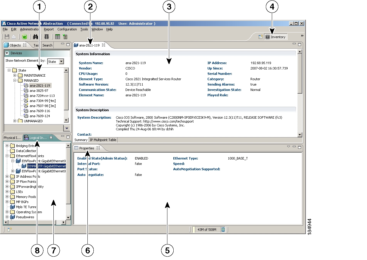
Viewing Logical Inventory Properties
The Logical Inventory tab displays a hierarchical (tree) view of the logical inventory, which might include routing tables, MP BGPs, OSPF networks, and so on for the selected network element in the Device drawer. The physical inventory is continuously updated for both status and configuration polling groups.
You can view the logical inventory properties by double-clicking any of the network element attributes in the Logical Inventory view.
Figure 3-2 shows the Logical Inventory tab in ANA.
Figure 3-2 Logical Inventory
The logical inventory lists the following:
•
•
•
•
•
•
•
•
•
•
•
•
These are not supported in ANA 4.0:
•
•
•
•
ANA supports real-time performance management data collection. For more information on this, see Collecting Data for Real-Time Performance Management, page 10-1.
See the Cisco Active Network Abstraction VNE Reference for the network element attributes that are displayed in the logical inventory. This document is available on Cisco.com at:
You can launch the Service Path Trace from the IP Flow Points in the logical inventory.
![]()
![]()
![]()
![]()
![]()
![]()
![]()
![]()
Posted: Mon Sep 24 07:34:45 PDT 2007
All contents are Copyright © 1992--2007 Cisco Systems, Inc. All rights reserved.
Important Notices and Privacy Statement.