|
|

Table Of Contents
Adding and Deleting Network Elements
Managing Network Auto Discovery and Seed Files
Understanding the Network Auto Discovery User Interface
Roles Required to Use Network Auto Discovery
Creating or Editing a Network Auto Discovery Configuration File
Performing Network Auto Discovery to Create a Seed File
Importing Network Elements Using the Seed File
Roles Required to Stop or Start the Gateway
Managing Units (and High Availability)
Roles Required to Manage Units
Viewing and Editing Unit Properties
Viewing and Editing AVM Properties
Prerequisites for Adding VNEs to AVMs
Viewing and Editing VNE Properties
Adding and Deleting Network Elements
These topics describe how to add, delete, and maintain network elements in ANA. You must have Administrator privileges to use these functions, unless otherwise noted.
•
Managing Network Auto Discovery and Seed Files
•
Managing Network Auto Discovery and Seed Files
ANA provides a Network Auto Discovery function that helps you create a list of elements in your network. In this way, you do not have to go through the tedious process of creating the list by hand. You can then refine the list to create your seed file, which specifies the elements you want ANA to manage. ANA then discovers those elements and create a model of them.
The following is an overview of this process, from performing network autodiscovery to importing the seed file.
1.
a.
For example, if you configure the RoutingTable discovery method with the Neighbor method as a dependent, ANA runs the Neighbor discovery first, then uses those results as input to the RoutingTable discovery method.
If desired, you can save the discovery configuration file to use later. See Creating or Editing a Network Auto Discovery Configuration File.
b.
2.
a.
b.
See Importing Network Elements Using the Seed File.
Related Topics
•
•
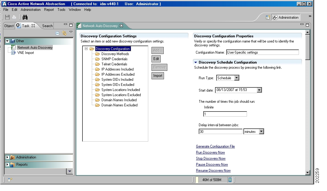
Understanding the Network Auto Discovery User Interface
The Network Auto Discovery user interface is where you configure the criteria you want ANA to use to create the seed file, as described in Creating or Editing a Network Auto Discovery Configuration File.
Figure 2-1 Network Auto Discovery User Interface
Roles Required to Use Network Auto Discovery
Table 2-1 lists the roles that are required to use Network Auto Discovery. For more information on roles, see Creating and Managing Users and Scopes, page 14-27.
Table 2-1 Roles Required to Use Network Auto Discovery
Create or edit autodiscovery settings
Administrator
Creating or Editing a Network Auto Discovery Configuration File
ANA discovers the elements in your network, based on parameters that you provide, such as discovery method, seed devices, and hop counts. You can specify the parameters and save them in a configuration file to be used or edited at another time. If you have a saved configuration file, you can import that file and make further edits.
Use this procedure to create or edit a discovery configuration file.
Step 1
Step 2
Step 3
a.
b.
c.
Step 4
a.
b.
c.
d.
Step 5
Note
To configure dependent methods:
a.
b.
c.
d.
Note
The ARP method must have RoutingTable as a dependent method.
The dependent method PingSweep must have the same seed IP address and hop counts as its parent method.e.
f.
Step 6
Step 7
a.
b.
Step 8
Note
Step 9
Step 10
Performing Network Auto Discovery to Create a Seed File
Once you have set your discovery settings as described in Creating or Editing a Network Auto Discovery Configuration File, you can perform (or schedule) the network autodiscovery using the following procedure. This creates the seed file that you use to add network elements to ANA.
Step 1
Step 2
•
•
The network autodiscovery process creates a list of the devices in the network in ANAHOME/Main/sfresources/deviceimport.xml (where ANAHOME is normally /export/home/ana40). This file is used to populate the VNE Import page, as described in Importing Network Elements Using the Seed File.
Importing Network Elements Using the Seed File
Once the network autodiscovery process has found the elements in the network according to your discovery criteria, you can specify which devices you want to add to ANA.
Step 1
Step 2
Step 3
a.
b.
Step 4
Step 5
To check on the results of the VNE import, check the log file at ANAHOME/Main/logs/SeedFile.log (where ANAHOME is the installation directory, normally /export/home/ana40).
ANA traverses the network to discover the network elements and use this information to create the model of the network. ANA uses internal algorithms to allocate the VNEs among AVMs, based on the memory and bandwidth required by the various network elements. Calculations are done based on the algorithms; it does not matter if the VNE is not active during the import.
Managing the Gateway
As described in ANA Architecture, page 1-5, the gateway enforces access control and security for all connections and manages client sessions. It maintains a repository of system settings, topological data, and snapshots of active alarms and events. The gateway also maps network resources to the business context, which enables ANA to contain information that is not directly contained in the network (such as VPNs and subscribers) and display it to northbound applications.
To connect to a gateway, download and install the client software on your client machine. Installing the gateway and client software is described in Cisco Active Network Abstraction 4.0 Installation and Setup Guide, along with other basic setup information.
Note
To get information about configured gateways:
Step 1
Step 2
The gateway workspace displays gateway information, such as its status, allocated and used memory, and AVMs configured on the gateway. (See Viewing and Editing AVM Properties, for information on the fields displayed in the table.)
You can also use the cmpctl command to start and stop the gateway and all component processes, or just perform a general check of the system status. The cmpctl command is located in ANAHOME/Main (ANAHOME is the installation directory, normally /export/home/ana40). It takes the following arguments:
start
Starts the gateway and component processes
stop
Stops the gateway and component processes
status
Displays the status of the gateway and component processes
You must be logged in as anauser to use this command. The following is an example:
# cd /export/home/ana40/Main# ./cmpctl status.-= Welcome to ana40-2, running Cisco ANA gateway =-. + Checking for services integrity: - Checking if host's time server is up and running [OK] - Checking if blood test webserver daemon is up and running [OK] - Checking if secured connectivity daemon is up and running [OK] - Checking if license server is up and running [OK] + Detected AVM99 is up, checking AVMs - Checking for AVM112's status [OK 0/119] - Checking for AVM113's status [OK 0/44] Checking for AVM66's status [OK 0/83] - Checking for JBoss status [OK] - Checking for AVM11's status [OK 3/523] - Checking for AVM55's status [OK 0/388] - Checking for AVM100's status [OK 0/95] - Checking for AVM0's status [OK 0/4874] Note Checking if host's time server is up and running is the only item that can safely have a status of DOWN. Everything else must display OK.cmpctl may display any of the following status indictors:
OK
Service or AVM is up and running.
DOWN
Service or AVM is down.
LOAD
Service or AVM is down, but the system is trying to start (load) it.
EVAL
License service is running with an evaluation license.
For performance information, see System Health and Diagnostics, page 14-34. If you would like to configure gateway high availability, contact ask-ana@cisco.com.
Roles Required to Stop or Start the Gateway
Table 2-4 lists the roles that are required to stop or start the gateway. For more information on roles, see Creating and Managing Users and Scopes, page 14-27.
Table 2-4 Roles Required to Stop or Start the Gateway
Stop or start the gateway using cmpctl
Administrator
Managing Units (and High Availability)
As described in ANA Architecture, page 1-5, the interconnected fabric of units comprises the lowest level of the ANA architecture. Each unit manages a group of network elements. Units host the autonomous VNEs. This creates a fabric of interconnected VNEs which can intercommunicate with other VNEs (regardless of which unit they are running on). ANA also provides a high ability mechanism to protect the system in case a unit malfunctions. If the unit is configured for high availability, ANA switches over to the redundant standby unit, with no loss of information.
For more information on high availability, see Managing Protection Groups (for Unit High Availability), page 14-9.
See these topics for more information:
•
•
Roles Required to Manage Units
Table 2-1 lists the roles that are required to manage units. For more information on roles, see Creating and Managing Users and Scopes, page 14-27.
Adding a New Unit
After you install the ANA software on a unit, you can add it to the ANA fabric. ANA automatically registers the unit in the registry and creates a transport uplink between the unit and the gateway. The units are linked to the gateway in a star topology.
In addition, administrators can enable or disable high availability for a unit. These settings enable the administrator to define to which protection group a unit is assigned, and whether it is enabled for high availability. For more information on high availability, see:
•
•
Before You Begin
Before adding a unit, you must install the ANA software on the unit as described in the Cisco Active Network Abstraction 4.0 Installation and Setup Guide.
To add a new unit:
Step 1
Step 2
Step 3
a.
b.
Note
c.
d.
Step 4
If the new unit is installed and reachable it starts automatically. The active unit is registered with the gateway. Specifically, the command creates the configuration registry for the new unit in the registry. In addition, ANA automatically creates the transport uplinks between the unit and the gateway.
Viewing and Editing Unit Properties
To view or edit a unit's properties:
Step 1
Step 2
Step 3
•
•
•
•
•
•
The Protection Group list displays the currently defined list of customized protection groups.
The workspace also lists the AVMs that are on that unit. For more information about AVM properties, see Viewing and Editing AVM Properties.
Step 4
The AVM HA check box defines whether the watchdog protocol is enabled. This should be selected. (See Managing the Watchdog Protocol, page 14-15.)
Note
Step 5
Removing a Unit
Before You Begin
Delete all the VNEs and unreserved AVMs before deleting a unit; see Deleting an AVM. The reserved AVMs cannot be deleted.
Use this procedure to remove a unit:
Step 1
Step 2
Step 3
Step 4
Managing AVMs
As described in ANA Architecture, page 1-5, AVMs are Java processes that provide the necessary distribution support platform for executing and monitoring multiple VNEs. AVMs and VNEs commonly reside on ANA units but they can also reside on an ANA gateway. The following AVMs are always created, and cannot be edited or deleted:
•
•
•
•
•
You can add AVMs to units or directly to a gateway.
The ANA Watchdog Protocol monitors the AVM processes to make sure any AVMs that have died are restarted. For information on the Watchdog Protocol, see Configuring AVMs for High Availability, page 14-15.
See these topics for more information:
•
•
•
Roles Required to Manage AVMs
Table 2-6 lists the roles that are required to manage AVMs. For more information on roles, see Creating and Managing Users and Scopes, page 14-27.
Understanding AVM Status
The status of AVMs and VNEs is affected by Admin Status and Operational Status. Admin Status comprises the administrative instructions that are sent to the AVM. Operational Status is the actual status of the AVM (for example, Up).
When moving an AVM, its status has a bearing on whether the file is reloaded. If its status is Up, it is reloaded; if its status is down, it is not reloaded. For more information about moving AVMs, see Moving an AVM. For more information about starting and stopping AVMs, see Starting and Stopping an AVM.
An AVM can have only one of the following statuses at a time:
•
•
•
•
The AVM status table describes the status of an AVM depending on the Admin and Operational Status, as displayed in the Status column of the AVMs table. The Admin Status comprises the administrative instructions that are sent to the VNE. The Operational Status is the actual status of the VNE, for example, Up.
Table 2-7 AVM Status
Up
Enabled
Up
Shutting Down
Disabled
Up
Down
Disabled
Down
Starting Up
Enabled
Down
Creating an AVM
ANA lets you define AVMs for ANA units. Every AVM in the ANA fabric is by default managed by the watchdog protocol. ANA enables the administrator to define AVMs for units, and enable or disable the watchdog protocol on the AVM.
Before You Begin
•
•
•
•
•
Note
Step 1
Step 2
Step 3
•
•
Note
•
•
Note
•
•
Note
Step 4
Creating the new AVM results in ANA providing the registry information of the new AVM in the specified unit. The AVM can now host VNEs. For more information, see Defining and Creating a VNE.
Viewing and Editing AVM Properties
To view and edit an AVM's properties:
Step 1
Step 2
Step 3
Step 4
•
•
•
•
Note
•
•
The workspace also lists the VNEs that are in that AVM. For more information about VNE properties, see Viewing and Editing VNE Properties.
Step 5
Note
Step 6
Starting and Stopping an AVM
Note
To start or stop an AVM:
Step 1
Step 2
Step 3
The AVM is started or stopped, and the appropriate status is displayed in the workspace as follows:
•
•
•
•
Moving an AVM
You can move an entire AVM between units.
Note
ANA automatically checks the status of the AVM and VNE before it is moved. This information is maintained in the memory.
If the AVM is up, it is stopped, and then it is moved to the target unit. After the move is completed, the AVM is reloaded, maintaining the status it was in before the move. For example, if it was up before the move, it remains up; if it was down, it remains down.
To move an AVM:
Step 1
Step 2
Step 3
The Move To dialog box displays a tree-and-branch representation of the selected ANA server and its units, excluding the unit in which the AVM is currently located. The highest level of the tree displays the ANA server. The branches can be expanded and collapsed to display and hide information.
Step 4
Step 5
For information about moving VNEs, see Moving One or More VNEs.
Deleting an AVM
If an AVM that you want to delete is running, it is stopped before being removed. This procedure deletes the registry information of the AVM in the specified unit. If there are VNEs running in the AVM, then an error message is displayed, and you cannot delete the AVM.
For more information, see Deleting a VNE.
Note
Before You Begin
Remove all VNEs from the AVM, or the deletion fails. See Deleting a VNE.
Step 1
Step 2
Step 3
Step 4
Note
Managing VNEs
As described in ANA Architecture, page 1-5, each Virtual Network Element (VNE) is assigned to manage a single network element instance, and contains a replica of that element. The VNEs maintain a live model of each network element and of the entire network. The information collected by a VNE depends on the VNE type and scheme. The VNE uses whatever southbound management interfaces the network element implements (for example, SNMP or Telnet).
See these topics for more information:
•
•
•
Roles Required to Manage VNEs
Table 2-6 lists the roles that are required to manage VNEs. For more information on roles, see Creating and Managing Users and Scopes, page 14-27.
Understanding VNE Status
VNE status is affected by the Admin Status and Operational Status. Admin Status results from the administrative instructions that are sent to the VNE. Operational Status is the actual status of the VNE, for example, up. For more information about Admin and Operational Status, see Understanding VNE Status.
When moving a VNE, its status, for example, up or down, has a bearing on whether the VNE is reloaded (up) or not (down). For more information about moving VNEs, see Moving One or More VNEs. For more information about starting and stopping VNEs, see Changing a VNE's State.
A VNE can have only one of the following statuses at a time:
•
•
•
•
•
In addition to the statuses described, the VNE can be placed in Maintenance mode. For example, a VNE's status can be up and in Maintenance mode. Network elements often undergo maintenance operations and planned outages. The ANA platform supports such maintenance operations without affecting the overall functionality of the active network.
While in Maintenance mode (temporary state) a VNE:
•
•
•
•
•
For more information about Maintenance mode, see Changing a VNE's State.
The VNE status table describes VNE status resulting from the Admin Status and Operational Status, displayed in the Status column of the VNE table. The Admin Status results from the administrative instructions that are sent to the VNE. The Operational Status is the actual status of the VNE, for example, up.
Table 2-9 VNE Status
Up
Enabled
Up
Shutting Down
Disabled
Up
Down
Disabled
Down
Starting Up
Enabled
Down
Unreachable
Enabled
Unreachable
The following examples illustrate Starting Up and Shutting Down status.
•
–
–
•
–
–
Prerequisites for Adding VNEs to AVMs
Do the following before you begin adding a VNE to an AVM:
1.
2.
3.
4.
Basic Network Element Information Required to Add a VNE
Make sure you have the following network element information before you add the VNE:
•
•
Choosing a VNE Type
When you add the VNE, you must choose a VNE type from a drop-down list. The types you can choose from are described in Table 2-10.
Choosing a VNE Scheme
The information collected by a VNE and populated in its model depends on the scheme you choose when adding the VNE to an AVM. ANA supports two schemes: Foundation and MPLSIOXSR. The scheme you should use depends on the type of network element you are adding, as shown in Table 2-10.
Table 2-11 Choosing a VNE Scheme
Foundation
You are adding a Cisco IOS network element, or a non-Cisco network element.
MPLSIOSXR
You are adding a Cisco IOS XR or Cisco IOX network element.
Gathering the Required Protocol Information for a Network Element
When you add a VNE, you are prompted to enter the information listed in Table 2-12.
Note
Defining and Creating a VNE
Each VNE corresponds to a network element and should only be added to the system once. As the VNE loads, ANA starts investigating the network element and automatically builds a live model of it, including its physical and logical inventory, its configuration, and its status. ANA also creates the registry information of the new VNE in the unit. The newly created VNE has an administrative status of down, and uses the default community strings and polling rates. The VNE inherits these properties from the configuration record that corresponds to the network element type.
These topics describe the steps you must perform to create a VNE:
Note
•
•
•
•
•
A VNE must be loaded into the bootstrap of the unit before it starts monitoring its underlying network element. This changes the administrative status of the VNE to up, and ensures that the VNE is loaded on subsequent restarts of the unit. Loading the VNE also starts the VNE immediately. For more information about the status of VNEs, see Understanding VNE Status.
Note
You can define and manage SNMP, Telnet/SHH, ICMP, and polling information for the appropriate VNEs in the New VNE dialog box. If desired, you can create VNEs that perform reachability testing, through ICMP only. Do this by creating the VNE, choosing ICMP for the VNE type, and defining the details in the ICMP area.
Before You Begin
Make sure you have all required information. See Prerequisites for Adding VNEs to AVMs.
Step 1
Step 2
Step 3
Note
•
•
•
•
•
Note
Step 4
Entering VNE General Information
The General tab lets you manage VNE information in the connected ANA.
To enter VNE general information:
Step 1
•
•
•
–
Note
See Entering VNE SNMP Information.–
–
•
Note
Step 2
•
Note
–
–
–
Step 3
•
•
Entering VNE SNMP Information
The SNMP tab lets you support polling and network element access using SNMP Version 1, Version 2, and Version 3.
To enter VNE SNMP information:
Step 1
•
Note
•
•
•
Note
Step 2
•
•
Step 3
•
–
–
–
If MD5 or SHA is selected, enter the required information in the following fields:
–
–
•
–
–
•
–
Note
Entering VNE Telnet/SSH Information
The Telnet/SSH tab lets you define the Telnet command sequence and support SSH for network element access (reachability) and investigation.
To enter VNE Telnet/SSH information:
Step 1
•
–
–
–
•
Step 2
•
Note
•
•
Use the Add, Remove, Up, and Down buttons to finalize your entries.
Note
Step 3
Entering VNE ICMP Information
The ICMP lets you enable repetitive transmission of packets to a network element for verification that the network element is reachable. You can define the polling rate in seconds for the VNE.
To enter VNE ICMP information:
Step 1
Note
Step 2
Entering VNE Polling Information
The Polling tab enables the administrator to associate a VNE with a previously created polling group, or customize polling intervals for a VNE.
Caution
In addition, you can configure a polling interval for a class of network elements; for example, for all Cisco routers.
To enter VNE polling information:
Step 1
•
For more information about creating customized polling groups, see Creating or Customizing a Polling Group, page 14-8.
•
Note
Step 2
a.
–
–
–
b.
–
–
Viewing and Editing VNE Properties
You can view and edit the properties of a VNE, such as the status and Telnet settings. Use this procedure to view and edit a VNE's properties.
Note
Step 1
Step 2
Step 3
•
•
For more details about the fields displayed in the VNE Properties dialog box, see
Defining and Creating a VNE. In addition to the fields displayed when adding a new VNE, the following fields and buttons are displayed:•
•
•
•
•
•
Step 4
Step 5
Step 6
Step 7
Changing a VNE's State
You can start or stop a VNE, or move it to Maintenance mode. Starting the VNE adds if to the server bootstrap. Stopping it removes it from the server bootstrap.
During normal operation, network elements often undergo maintenance operations and planned outages such as software upgrades, hardware modifications, cold reboots, and so on. The ANA platform supports such maintenance operations without affecting the overall functionality of the active network. Neighboring VNEs do not generate alarms that are related to links to or from the maintained VNE.
While in maintenance state (temporary state) a VNE:
•
•
•
•
•
The VNE blocks all provisioning flows that run through it. A network element in maintenance state can be disconnected and restarted, and this does not result in link-down alarms. Upon restart, the VNE receives only persistent information and returns to its latest known configuration. The topology links are renewed automatically.
To change the VNE's state:
Step 1
Step 2
Step 3
Step 4
•
•
•
Moving One or More VNEs
You can move single and multiple VNEs between AVMs. The VNEs that are moved are unloaded from the old unit, and after they are reloaded on the new unit, their original status is maintained.
To move a single VNE or multiple VNEs:
Step 1
Step 2
Step 3
The Move To dialog box displays a tree-and-branch representation of the selected ANA server, its units, and AVMs, excluding the AVM in which the VNE is currently located. The highest level of the tree displays the ANA server. The branches can be expanded and collapsed to display and hide information.
Step 4
Step 5
Deleting a VNE
You can delete a VNE from an AVM (and its unit). When you delete a VNE, ANA stops the VNE and deletes all VNE references from the system and golden source, which includes the registry information of the VNE in the specified unit. A VNE that has been removed no longer appears in any future system reports. If the VNE has any static links, you must remove them before removing the VNE (dynamic links are automatically removed).
Since all VNE information is deleted, adding the VNE again requires you to enter all the VNE information.
Before You Begin
If the VNE you plan to delete has any static links, remove them. Dynamic links are automatically removed.
Step 1
Step 2
Step 3
Step 4
Step 5
![]()
![]()
![]()
![]()
![]()
![]()
![]()
![]()
Posted: Mon Sep 24 07:18:11 PDT 2007
All contents are Copyright © 1992--2007 Cisco Systems, Inc. All rights reserved.
Important Notices and Privacy Statement.