|
|

Table Of Contents
Understanding the Job Management User Interface
Creating a Banner (Message of the Day)
Roles Required to Manage Polling Groups
Creating or Customizing a Polling Group
Managing Protection Groups (for Unit High Availability)
Roles Required to Manage Protection Groups
Configuring Units for High Availability
Managing the Watchdog Protocol
Understanding the Trap Forwarding User Interface
Configuring a Trap Forwarding Service
Specifying Preferences for ANA Features
Configuration Archive Preferences
Creating and Managing Users and Scopes
Creating and Managing ANA User Accounts
Logging Into the Diagnostic System
Checking Basic System Health (CPU, Memory, JBoss)
Scheduling and Running Diagnostic Jobs
Creating Basic System Health (CPU, Memory) and Traffic Graphs
Viewing Diagnostic System Alarms
Gathering Logs for Troubleshooting Purposes
Understanding the ANA Registry
How Changes Affect the Registry
ANA Administration
These topics describe information to help you administer your ANA network by adding and moving VNEs, adding users and scopes, and so forth. These topics also explain how to maintain the machines on which ANA is running; for example, backing up the system, applying software updates, and checking overall system health using the diagnostics software.
Information describing backend services, processes, and logs that are part of the ANA system are described in Cisco Active Network Abstraction 4.0 Installation and Setup Guide.
Most of the administrative functions are performed from the Administration perspective. You must have Administrator privileges to use these functions:
•
Creating a Banner (Message of the Day)
•
•
•
•
•
•
Managing Jobs
Use the Job Management function to administer jobs that have been scheduled, such as system backups. You can schedule, suspend, resume, delete, and purge jobs. You cannot edit a job; to change it, you must delete the old job and create a new job.
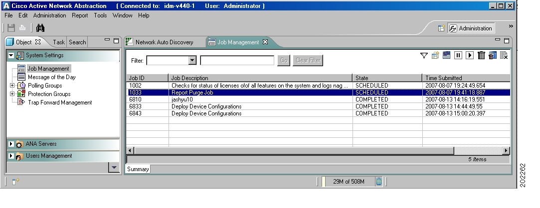
Understanding the Job Management User Interface
Figure 14-1 shows the Job Management user interface, listing the jobs that ANA is currently managing.
Figure 14-1 Job Management User Interface
The following tool buttons are located at the top right of the Job Management workspace.
Table 14-1 Job Management Icons
Schedules a job
Suspends a job.
Resumes a job.
Deletes a job.
Purges a job.
Cancels a job.
Roles Required to Use Job Management
If you created a job, you can perform all of the Job Management functions listed in Table 14-1, except for job purging. Only users with Administrator privileges can purge jobs, as well as perform all other Job Management functions. For more information on roles, see Creating and Managing ANA User Accounts.
Browsing and Controlling Jobs
To browse and control jobs:
Step 1
Step 2
Step 3
•
•
Step 4
Purging deletes all historical information. You can apply only one schedule to a job.
Step 5
Creating a Banner (Message of the Day)
You can configure a banner that is displayed whenever a user logs into the ANA system. You must acknowledge the message to use ANA.
Note
Roles Required to Create a Message of the Day
You must have Administrator privileges to create a banner. For more information on roles, see Creating and Managing ANA User Accounts.
Creating a Banner
If you do not want to display a banner, simply leave the Message of the Day fields empty.
To create or edit a banner:
Step 1
Step 2
Step 3
Step 4
The message displays when any users log in to the ANA system.
Managing Polling Groups
When you add a VNE to ANA, one of the areas you configure is the polling settings. As described in Defining and Creating a VNE, page 2-21, you have two options for specifying the polling parameters for the VNE:
•
•
These topics describe the second option—polling groups—and how they work.
The units poll the network elements to discover and display accurate and up-to-date information about the network. The system periodically triggers polling at set intervals. The polling rates can be customized or optimized by a user with Administrator privileges. You can fine-tune the frequency with which information is retrieved from the managed elements to enable a high degree of control and flexibility over the amount of network traffic used by the various VNEs. For example, core network elements can be assigned to a polling group (all network elements use the same polling profile) that specifies a higher frequency for status but a lower frequency for configuration-related information, while edge or access network elements can be polled more frequently for system and configuration-related information. Managed network service operators, for example, can use polling groups to reflect their agreement with customers so that premium customer network elements are polled more frequently than normal network elements.
ANA polls only network elements that are in the Managed state.
Polling intervals depend on the type of information that is being queried. The intervals represent the amount of time between investigations of the network element for the data specified. You can adjust these intervals as described in Creating or Customizing a Polling Group. The default-pg polling group has the following settings:
•
•
•
•
•
Core devices can be assigned to a polling group (all devices use the same polling profile) that specifies a higher frequency for status but a lower frequency for configuration-related information. Edge or access network elements can be polled more frequently for system and configuration-related information. Managed network service operators, for example, can use polling groups to reflect their agreement with customers so that premium customer network elements are polled more frequently than normal network element.
Adaptive Polling
In addition to defined polling intervals, VNEs implement adaptive polling to make sure that the element is not overloaded. For example, if CPU usage is high, ANA may defer some polling to avoid overloading the managed element.
When a VNE exceeds the maximum CPU usage threshold value, an alarm is sent, and the VNE is automatically transferred to a slow polling interval. For example, the VNE is polled less regularly and a delay is added between the commands. When the CPU usage threshold values for the VNE fall below the clear threshold value, an alarm is sent and the VNE returns to normal polling.
Note
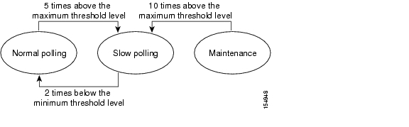
When a VNE is using normal polling and CPU usage is high, ANA waits for the maximum CPU usage threshold value (upper tolerance level) to be exceeded 5 times (the default), and then the VNE moves to slow polling, as shown in Figure 14-2.
Figure 14-2 Polling Threshold Levels
If the VNE is using slow polling after it has been checked 5 times, then it is checked 10 more times (the default) to see whether the CPU usage is still high. If usage remains high, the VNE is moved to Maintenance mode. When the VNE is in Maintenance mode, it is not polled. (See Understanding VNE Status, page 2-18.)
Note
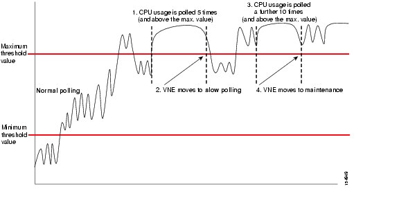
In Figure 14-3, CPU usage is polled 5 times. Because CPU usage is above the maximum value, the VNE is moved to slow polling. The CPU usage is then polled 10 more times. Because CPU usage remains above the maximum value, it is moved to Maintenance mode.
Figure 14-3 Polling and CPU Usage—VNE Remains at Unacceptable Level
When the VNE is using slow polling and CPU usage drops to an acceptable level (below the maximum value), ANA continues to poll the VNE. If the VNE remains at that level for two consecutive polls, ANA returns the VNE to normal polling.
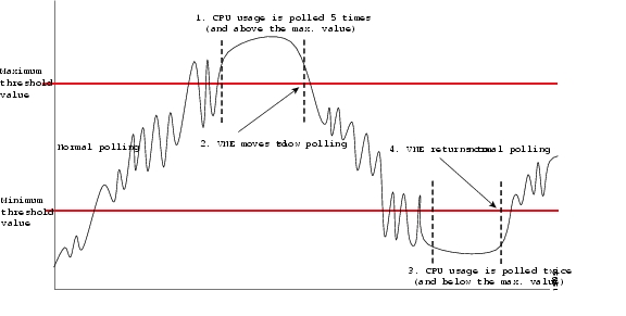
In Figure 14-4, CPU usage is polled 5 times. Because the usage remains above the maximum value, the VNE is moved to slow polling. However, in this case, CPU usage returns to an accepted level (below the maximum value). The VNE is polled twice more, and because CPU usage remains at an acceptable level, it is moved back to its normal polling.
Figure 14-4 Polling and CPU Usage—VNE Returns to Acceptable Level
If CPU usage is high and a slow polling interval is used, and the AVM goes down and is then restarted, the AVM maintains the slow polling interval for the VNE.
Roles Required to Manage Polling Groups
Table 14-2 lists the roles that are required to manage polling groups. For more information on roles, see Creating and Managing ANA User Accounts.
Table 14-2 Roles Required to Manage Polling Groups
Create or edit a polling group
Administrator
Delete a polling group
Administrator
Creating or Customizing a Polling Group
You can create a new polling group to be used when defining a VNE. For more information, see Managing VNEs, page 2-17. If you change an existing polling group, the changes affect all VNEs and network elements using that polling group.
Caution
To create or customize a polling group:
Step 1
Step 2
Step 3
•
–
–
•
–
–
–
•
–
–
Step 4
The new polling group can be used when defining a new VNE. See Managing VNEs, page 2-17.
Deleting a Polling Group
You can delete polling groups as long as they are not being used by any VNEs or network elements. You cannot delete the default polling group.
To delete a polling group:
Step 1
Step 2
Step 3
The polling group is deleted from the Polling Group table.
Managing Protection Groups (for Unit High Availability)
The high availability architecture ensures continuous availability of ANA functionality, by detecting and recovering from a wide range of hardware and software failures. The distributed design of the system enables the impact radius caused by a single fault to be confined. This prevents all types of faults from setting into motion the "domino" effect, which can lead to a crash of all the management services.
The high availability of the server backbone is achieved at several complementing levels; for example:
•
•
•
By default, all the units in the ANA fabric belong to one group, the default-pg protection group. A protection group is a collection of units, one of which is assigned to be the standby unit. The administrator can change the default setup of the units by customizing protection groups (clusters) and then assigning units to these groups.
Note
Watchdog Protocol and Process Monitoring
Watchdog Protocol monitors the AVM processes to make sure any AVMs that have failed are restarted, as follows. The Watchdog Protocol is normally denoted in the UIs as AVM Protection. Each unit executes several processes: one control process and several AVM processes that execute VNEs. Each process within the unit is completely independent. The isolation concept is tailored throughout the design: a failure of a single process does not affect other processes on the same machine. The exact number of processes on each unit depends on the capacity and computational power of the unit.
The control process executes a Watchdog protocol, which continuously monitors all other processes on the unit. This Watchdog protocol requires each AVM process to continuously handshake with the control process. A process that fails to handshake with the control process after a number of times (is "stuck") is automatically stopped and reloaded.
The dynamic design of the control process implements runtime adaptation and escalation. The escalation procedure moves the AVM to suspended mode, and the process is suspended. An example of an escalation procedure is to stop reloading a process that has crashed more than N times within a given period, because it is suspected of having a recurring software problem.
The reload process is local to the unit, and thus very rapid, with a minimal amount of down time. Since the process can use its previous cache information (temporary persistence used to improve performance), once the stuck process is detected, reloading the process takes only a few seconds with no data loss.
All watchdog activity is logged, and an alarm is generated and sent when the watchdog reloads a process.
For information on how often ANA attempts to restart an AVM, see High Availability Events.
Unit N+m High Availability
The clustered N+m high availability mechanism within the ANA fabric is designed to handle the failure of a unit. Such failures include hardware failures, operating system failures, power failures, or network failures, which disconnect a unit from the ANA fabric.
Unit availability is established in the gateway, running a Protection Manager process, which continuously monitors all the units in the network. Once the Protection Manager detects a unit that is malfunctioning, it automatically signals one of the m servers in its cluster to load the configuration of the faulty unit (from the system registry), taking over all its managed network elements. This design provides many possibilities for trading off protection and resources. These possibilities range from just segmenting the network into clusters without any extra machines, up to having a warm-swappable empty unit for each unit in the setup. It is recommended that units be clustered according to geography and that an additional empty unit be added to heavily loaded clusters.
The switchover of the redundant standby unit does not result in any loss of information in the system, because all the information is autodiscovered from the network, and no persistent storage synchronization is required. Hence, the redundant standby unit relearns all the information from the network elements, with no danger of persistent information corruption. Furthermore, where there is cluster saturation (when, more than one unit in a cluster fails at the same time and there are no extra machines), the remaining units continue to operate and manage their network map normally.
When a unit is configured it can be designated as being an active or standby unit. The active units (excluding the standby unit) that are connected to the gateway are known as a protection group. The standby unit that is configured for the gateway is linked to that protection group. The administrator can define more than a single protection group. Each protection group defined has a set of protected units and a protecting standby unit.
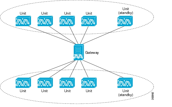
Figure 14-5 shows to protection groups (a cluster) of units, which are controlled by one gateway. In each cluster, one unit is configured as the standby for the protection group. An alternative would be for the two groups two overlap, with the same unit acting as the standby.
Figure 14-5 ANA Gateway/Unit Architecture for High Availability
In the above configuration, when the gateway determines that one of the units in the protection group has failed, it notifies the protection group's standby unit to immediately load the configuration of the failed unit. The standby unit loads the configuration of the failed unit, including all its AVMs and VNEs, and functions as the failed unit.
These events are all recorded in the system log, which enables you to take the necessary action to bring the failed unit up again. When the failed unit becomes operational, you can decide whether to configure it as the new standby unit or to reinstate it to the protection group and configure another unit as the standby unit.
The high availability mechanism attempts to load an AVM after it crashes (whether the AVM comes up or not), a maximum of 5 times. Thereafter, the high availability mechanism does not try to reload this AVM again.
Roles Required to Manage Protection Groups
Table 14-3 lists the roles that are required to use the Administration perspective functions. For more information on roles, see Creating and Managing ANA User Accounts.
Configuring Units for High Availability
These topics describe customizing protection groups, configuring units for high availability, and configuring standby units. These are the steps you must perform to set up high availability:
1.
2.
3.
These topics provide additional information on managing high availability:
•
•
•
Creating a New Protection Group
Administrators can change the default setup of the units by customizing protection groups (clusters) and then assigning units to these groups. By default, all units belong to the default-pg protection group.
To create and customize a protection group:
Step 1
Step 2
Step 3
Step 4
Step 5
The new protection group is displayed in the workspace of the window.
Controlling Unit High Availability and Standby Status
When you create a unit, you can enable or disable high availability. You can also designate the unit to be a standby unit. This is done through choices that you make when you create the unit.
Note
This procedure describes how to enable or disable high availability, and how to configure a unit to be a standby server:
Step 1
a.
b.
c.
Step 2
Step 3
Step 4
•
•
Note
•
•
•
Step 5
The new unit is displayed in the tree pane and the workspace of the window. If the new unit is installed and reachable it starts automatically.
Checking and Changing the Assignment of Units to Protection Groups
The administrator can view the protection groups to which the units are currently assigned. In so doing, the administrator can, at a glance, verify that the configuration or assignment matches the initial deployment plan.
To check the assignment of units to protection groups:
Step 1
Step 2
Step 3
a.
b.
c.
Switching to a Standby Unit
If you have enabled high availability on a unit, when the gateway discovers that one of the active units has had a high availability event (such as a timeout), ANA automatically transfers all data from the failed unit to a standby unit in the same protection group. If you have configured more than one standby unit for a protection group, the gateway randomly chooses the redundant unit to activate.
You can also manually switch to a standby server (for example, when you want to temporarily shut down a unit for maintenance).
To manually switch to the standby unit:
Step 1
Step 2
Step 3
The standby unit becomes the active unit and is displayed in the Servers tree. The original unit is removed from the setup and can be safely shut down (note that it is no longer displayed).
Viewing and Editing Protection Group Descriptions
If desired, you can view and edit a protection group's description:
Step 1
Step 2
Step 3
Step 4
Managing the Watchdog Protocol
These topics describe how ANA enables the administrator to define AVMs for units and enable or disable the watchdog protocol on the AVM.
•
•
Configuring AVMs for High Availability
Every AVM in the ANA fabric is by default managed by the watchdog protocol, though it can be disabled by users with Administrative privileges. For more information about the watchdog protocol, see Watchdog Protocol and Process Monitoring.
Note
To define an AVM:
•
•
•
To define an AVM:
Step 1
Step 2
Step 3
Note
The Enable AVM Protection checkbox is displayed in the New AVM dialog box. Click this option to enable the watchdog protocol on the AVM.
Note
Step 4
Step 5
Adding the new AVM creates the registry information of the new AVM in the specified unit, and the AVM can now host VNEs.
Viewing and Editing the Watchdog Protocol Settings
In addition to viewing and editing various AVM properties, you can enable or disable the watchdog protocol.
Note
Step 1
Step 2
Step 3
Step 4
The AVM's new properties are displayed in the workspace.
High Availability Events
Table 14-4 provides a list of the high availability events displayed in the Troubleshooting perspective and provides the defaults for the failover parameters.
Table 14-4 Default Settings for Failover
Grace period (time from system startup, in which events are not raised)
1800000 (30 minutes)
Delay
Timeout for AVMs
300000 (5 minutes)
Timeout
Timeout for units
300000 (5 minutes)
Note
Timeout
AVMs repeatedly not responding
Tries a maximum of 5 times to restart the AVM, within 10800000 ms (180 minutes) (if more than 5 suspends the AVM).1
maxTimeoutReloadTime
maxTimeoutReloadTries
1 If an AVM is restarted, you can view the log files for more details. The log filenames are in the format avm.restart1, avm.restart2, and so forth, up to avm.restart5. If you want to change the number of restarts, contact ask-ana@cisco.com.
When an AVM initially starts, ANA waits until a grace period of 30 minutes has elapsed before attempting to restart the AVM. This is because an AVM can be very busy during initial startup, and may not respond to availability queries in a timely manner. If the AVM has not started by the end of the 30 minutes, ANA attempts to restart the AVM up to 5 times. If the AVM does not restart, ANA suspends the AVM and displays a message saying the AVM has been "suppressed." The AVM is displayed as Disabled. To re-enable the AVM, you must stop it and then start it again, as described in Starting and Stopping an AVM, page 2-15. (If the AVM responds to any high availability queries during the 30 minute grace period, the grace period is skipped.)
This grace period also applies to units; in other words, ANA does not perform any high availability operations on AVMS or units until the 30 minutes has elapsed.
A list of the high availability events is provided in Table 14-5.
Table 14-5 High Availability Events
The AVM times out (see Grace period in Table 14-4)
AVM 107 not responding: ANA Unit = 1.1.1.1 AVM = 107
This is followed by one of the following:
Major
AVM 107 is shutting down. ANA Unit = 1.1.1.1
Minor
AVM 107 is starting. ANA Unit = 1.1.1.1
Minor
The AVM repeatedly does not respond (see AVMs repeatedly not responding in Table 14-4)
AVM 107 suppressed: ANA Unit = 1.1.1.1 AVM = 107
Major
The unit times out (when a standby unit is available) (see Timeout for units in Table 14-4)
Server 1.1.1.1 not responding. Raising Redundant machine = 3.3.3.3
Major
A unit times out (without a standby unit being available) (see Timeout for units in Table 14-4)
Server 1.1.1.1 not responding. No Redundant machine available
Major
Manually switching to the standby unit
Server 1.1.1.1 manual failover initiated No Redundant machine available
Major
Server 1.1.1.1 manual failover initiated Raising Redundant machine = 3.3.3.3
Major
Trap Forwarding
You can configure ANA to forward SNMP traps and syslog messages to other destinations so that OSS clients can receive these traps on their UDP or TCP ports. You can also create filters, so that only the traps that are of a certain severity or from a certain IP address are forwarded. Before they are forwarded, all traps are converted to SNMPv2 and are formatted according to the CISCO-EPM-NOTIFICATION-MIB. By default, they are forwarded to port 162 on the destination machine. If the destination is not available, the messages are dropped.
For information on supported traps, see Tracking Faults, page 12-1.
Understanding the Trap Forwarding User Interface
The following tool buttons are located at the top right of the Trap Forwarding Service workspace.
Table 14-6 Trap Forwarding Service Tool Buttons
Creates a new trap forwarding service.
Edits the trap forwarding service.
Deletes the trap forwarding service.
Roles Required to Use Trap Forwarding
Table 14-7 lists the roles that are required to use the Trap Forwarding functions. For more information on roles, see Creating and Managing ANA User Accounts.
Configuring a Trap Forwarding Service
Follow this procedure to set up trap forwarding:
Step 1
Step 2
Step 3
Step 4
a.
b.
–
–
–
Step 5
Step 6
Specifying Preferences for ANA Features
Administrators can configure specific preferences for ANA network resource management features, such as specifying the import directory for network element images, or the maximum number of network element configurations that can be archived. This is done using the functions in the Preferences drawer in the Administration perspective (which is under the Tasks tab). These topics describe how to specify the settings:
•
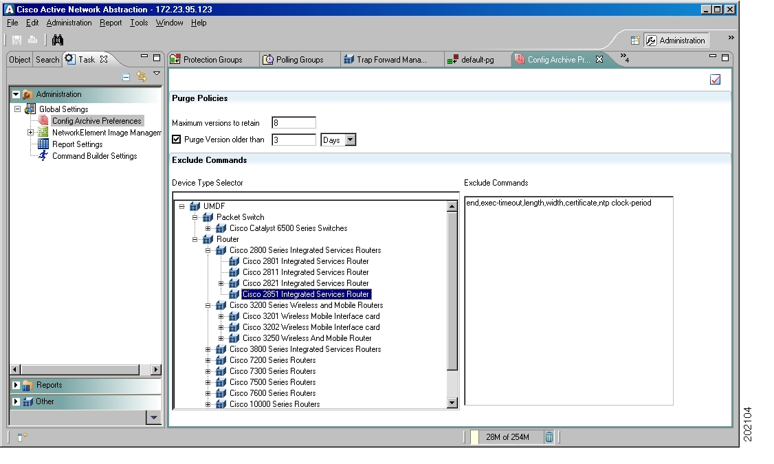
Configuration Archive Preferences
This topic explains how to set Configuration Archive to purge old archives and exclude specific commands when comparing configurations. Purging archives is disabled by default.
Understanding the Configuration Archive Preferences User Interface
Figure 14-1 shows the Configuration Archive preferences user interface.
Figure 14-6 Configuration Archive Preferences User Interface
The following tool button is located at the top right of the Configuration Archive Preferences workspace.
Table 14-8 Configuration Archive Preferences Tool Button
Immediately applies your Configuration Archive settings
Roles Required to Use Configuration Archive Preferences
Table 14-8 lists the roles that are required to configure the preferences for Configuration Archive. For more information on roles, see Creating and Managing ANA User Accounts.
Table 14-9 Roles Required to Set Configuration Archive Preferences
Set or edit Configuration Archive settings
Administrator
Adjusting Configuration Archive Preferences
Step 1
Step 2
Step 3
Note
•
•
Caution
Step 4
a.
–
–
–
Note
b.
Step 5
NEIM Preferences
This topic explains how to configure the credentials required to log in to a vendor webbiest and download a new network element image using Network Element Image Management (NEIM). It also explains how to change the default directory into which network element images are imported.
Understanding the NEIM Preferences User Interface
The following tool buttons are located at the top right of the NEIM preferences workspace.
Roles Required to Change NEIM Preferences
Table 14-11 lists the roles that are required to configure NEIM preferences. For more information on roles, see Creating and Managing ANA User Accounts.
Adjusting NEIM Preferences
Use this procedure to set vendor credentials so that you can log in to a vendor web site to download network element images. Also use this procedure to change the import directory for these images.
Before You Begin
If you plan to change the import directory for network element images, make sure the directory is empty and has the proper permissions (anauser must have read, write, and execute permissions).
Step 1
Step 2
Step 3
a.
b.
c.
Step 4
a.
b.
c.
Reports Preferences
The Reports preferences function controls the number of archived reports stored by ANA.
Roles Required to Specify Preferences for Reports
Table 14-12 lists the roles that are required to configure the preferences for Reports. For more information on roles, see Creating and Managing ANA User Accounts.
Table 14-12 Roles Required to Set Reports Preferences
Set or edit report settings
Administrator
Adjusting Preferences for Reports
The generated report is purged based on the purge policy you specify while creating the report job or by using the Report Setting in the Administration perspective.
You can purge reports based on two criteria:
•
The oldest report is purged when the maximum number is reached. For example, if you set the maximum versions to retain to 10, when the eleventh version of a report is archived, the earliest (first version) is purged to retain the total number of latest archived report versions at 10.
•
ANA does not purge the archived reports if the number of archived reports is less than or equal to the specified minimum number of versions to retain.
The purge policy that you specify while creating the Inventory Summary report job overrides the policy that you have specified in the Report Settings of the Administration perspective in the Task tab.
Step 1
Step 2
•
•
•
•
Step 3
If at any time you want to restore the settings to their defaults, click Restore Defaults.
Command Builder Preferences
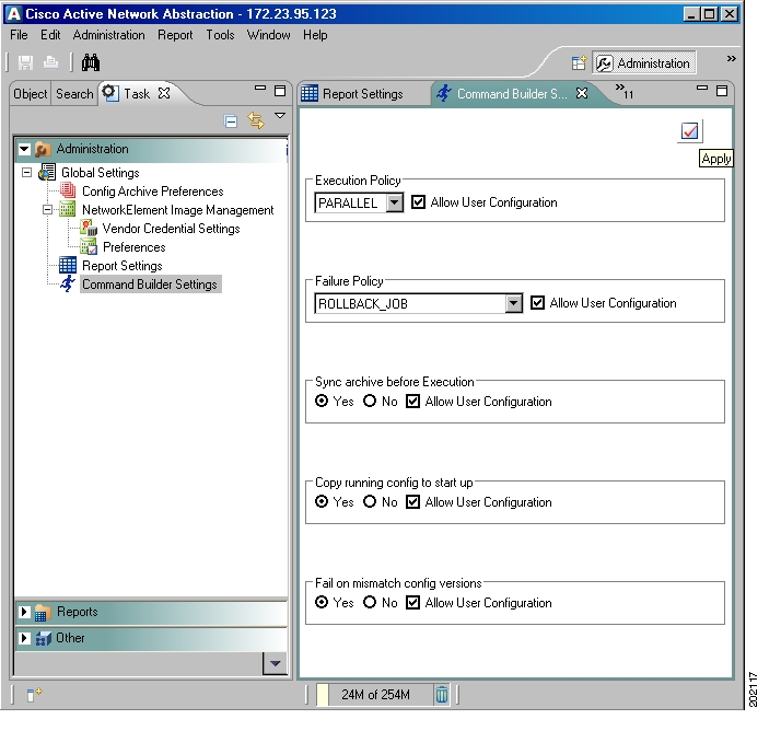
This topic explains how to configure default parameters for Command Builder policies, so that the policies are applied to future Command Builder jobs.
Understanding the Command Builder Preferences User Interface
Figure 14-1 shows the Command Builder preferences user interface.
Figure 14-7 Command Builder Preferences User Interface
The following tool button is located at the top right of the Command Builder workspace.
Table 14-13 Command Builder Preferences Tool Button
Immediately applies your Command Builder settings
Roles Required to Use Command Builder Preferences
Table 14-14 lists the roles that are required to configure the preferences for Command Builder. For more information on roles, see Creating and Managing ANA User Accounts.
Table 14-14 Roles Required to Set Command Builder Preferences
Set or edit Command Builder preferences
Administrator
Adjusting Command Builder Preferences
Use this procedure to adjust the preferences for Command Builder:
Step 1
Step 2
Step 3
•
–
–
•
–
–
–
•
•
•
–
–
Step 4
Creating and Managing Users and Scopes
When you create a user account, you must assign the following to a user:
•
•
Users cannot do anything with ANA until you assign a scope to them. You can also assign a user different roles for different scopes. In this way, the administrator controls the granularity of what users can do on different network elements.
Roles
ANA implements a security engine that combines a role-based security mechanism that is applied to scopes of network elements granted per user. The system supports user account creation, multiple network element scope definition, and a set of four pre-defined roles for security and access control to allow different system functions:
•
•
•
•
To configure user accounts and roles, see Creating and Managing ANA User Accounts.
Scopes
A scope is a named collection of managed network elements that have been grouped to allow a user to view and manage the network elements according to a given role. Grouping can be based on geographical location, network element type (such as DSLAM, router, software, and so on), network element category (such as access, core, and so on), or any other division according to the administrator's requirements.
A user who has been assigned a scope can view and manage the network elements within this scope according to the role assigned to you as defined by the scope. You cannot view any information regarding network elements, including basic properties, inventory, and alarms, that are outside your scope.
For information on creating and managing scopes, see Creating and Managing Scopes.
Creating and Managing ANA User Accounts
User accounts are created by using the functions in the User Management drawer. This drawer is in the Administration perspective under the Object tab. The functions available from this drawer include managing general user information as well as security access rights and forced login changes. You can also monitor a user's last login time.
Note
The new user is created with a set of pre-defined system defaults, as follows:
•
•
See these topics for more information:
•
•
•
Roles Required to Manage User Accounts
Table 14-15 lists the roles that are required to manage user accounts. For more information on roles, see Creating and Managing ANA User Accounts.
Creating User Accounts
To create a user account:
Step 1
Step 2
Step 3
•
–
–
–
•
•
•
–
–
–
–
–
•
•
Note
•
Step 4
Note
Step 5
a.
b.
–
–
Step 6
Step 7
Viewing and Editing a User's Password
You change a user's password in his or her account. You can also force users to change their passwords by choosing the Force Password Change at Next Login checkbox (see Creating User Accounts).
To change a user's password:
Step 1
Step 2
Right-click a selected user and choose Reset Password. The Reset User Password dialog box is displayed.
Step 3
Step 4
Step 5
Users can change their own password using Tools > Change Password.
Viewing and Changing User Account Properties
You can manage or edit general user account information, including a user's scope information. To change a user's password, see Viewing and Editing a User's Password.
To view or change user account properties:
Step 1
Step 2
Step 3
•
•
•
•
•
•
•
The Security area controls the user's ability to view and manage the network resource management features and elements by granting the user scopes and security access roles. By default, a new user is assigned a viewer security access role. The following information is displayed in the Security area:
•
•
•
You can edit the user's scope settings as follows:
•
•
•
Step 4
•
•
Step 5
Step 6
Deleting a User Account
When you delete a user account, the user-related information is deleted from the database and a security event is generated.
Step 1
Step 2
Step 3
Creating and Managing Scopes
You can group a collection of managed network elements together into a scope, to control what network elements users can view and manage. User cannot do anything with managed network elements until a scope is assigned to them.
Multiple scopes can be assigned to a single user, and a single scope can be assigned to multiple users. When the scope is assigned to a user, you must also designate the user's security access role in that scope. This controls the user's actions in that scope. See Editing a Scope and Viewing Scope Properties.
See these topics for more information:
•
•
Understanding the Scopes User Interface
The Scopes function is location in the Users Management drawer (under the Object tab in the Administration perspective). When you double-click Scopes, all defined scopes are listed.
The following tool buttons are located at the top right of the Configuration Archive Preferences workspace.
Table 14-16 Scopes Tool Buttons
Adds network elements to the scope.
Deletes the scope.
Roles Required to Manage Scopes
Table 14-17 lists the roles that are required to manage scopes. For more information on scopes, see Creating and Managing Scopes.
Table 14-17 Roles Required to Manage Scopes
Create a new scope
Administrator
View scope properties
Administrator
Edit an existing scope
Administrator
Delete a scope
Administrator
Creating a New Scope
To create a scope:
Step 1
Step 2
Step 3
Step 4
Step 5
Editing a Scope and Viewing Scope Properties
You can edit the details of a scope and view its properties using the following procedure:
Step 1
Step 2
Step 3
Step 4
Step 5
Deleting a Scope
Use this procedure to delete a scope.
Note
To delete a scope:
Step 1
Step 2
Step 3
System Health and Diagnostics
The Administration perspective provides the memory utilization information for gateway and units (physical, allocated, and used). ANA also provides a web-based monitoring client tool so you can ensure that the gateway, units, and AVMs are functioning correctly, and troubleshoot them when problems arise. The following is provided:
•
•
•
•
•
•
Logging Into the Diagnostic System
To access the diagnostic client, enter the following URL in your browser:
http://server_name:1310/
You are prompted for a username and password. The username is normally root, and the password is the password for anauser.
Checking Basic System Health (CPU, Memory, JBoss)
The information under the Machines tab provides details about the gateways, units, and AVMs. It also provides other details and tools that are used by Professional Services, but you are likely to be interested in the basic CPU and memory information displayed when you choose a gateway or unit.
Step 1
Step 2
ANA displays information on all gateways and units in the Machines Status table. (Most of this information is also displayed graphically under the Graphs tab.) Alarms represent system alarms generated by the diagnostic framework, since the gateway was started; mes_byt_rec contains the message bytes received by the transport module of the legacy gateway.
Step 3
•
•
•
Step 4
ANA populates the Management Commands area and lists all available commands that can be run on the AVM services.
Note
Scheduling and Running Diagnostic Jobs
The Tasks tab provides tools for configuring a variety of diagnostic jobs for AVMs. Once you have configured a job, you can schedule it to run on a regular basis.
Note
Step 1
Step 2
Step 3
Creating Basic System Health (CPU, Memory) and Traffic Graphs
The Graphs tab displays monitoring parameters for gateways, units, AVMs, and the database in a graphical representation.
Step 1
Step 2
•
•
•
Viewing Diagnostic System Alarms
The Alarms tab displays all of the system alarms generated by the diagnostics framework (not network element alarms).
Note
Step 1
Step 2
Getting Database Information
The Database tab displays text and graphical information about the database, such as executions and connected users. You can customize the graphical data by selecting a specific period you are interested in. In addition, the Tools tab provides some utilities for checking the database status, active connections, and size.
Note
Step 1
Step 2
The database name, version, status, and size are listed, along with the number of executions and connections. You can check specific time periods using the Period drop-down list.
Step 3
a.
b.
–
–
–
The result is displayed in the Tool Execution area.
To perform administrative tasks on your database, see your vendor documentation.
Gathering Logs for Troubleshooting Purposes
The Tools tab provides a function for collecting all gateway and unit log files, and copies them onto the gateway in a directory you specify.
Before You Begin
•
•
Step 1
Step 2
Step 3
Step 4
Step 5
a.
b.
Step 6
a.
b.
Checking Connectivity
The Tools tab provides a function whereby you can check the connectivity between a gateway and a unit, or a unit and a network element. You must know the IP addresses of the gateway, unit, or network element to use this tool.
Step 1
Step 2
Step 3
Step 4
•
•
Step 5
System Security
This topic describes the key elements of ANA security.
Licenses
ANA supports several different types of licenses which control what can be done on the ANA system. When a license is nearing its expiration, the licensing framework starts generating messages to remind you to renew or upgrade your license. For complete information on licenses, see Cisco Active Network Abstraction 4.0 Installation and Setup Guide.
Audit Trails
Audit and Security events are listed in the Audit table in the Troubleshooting perspective.
Authentication and Authorization
Whenever a user logs into the ANA system, ANA authenticates the user by verifying the username and password. After 5 invalid attempts, ANA disables the user's account and a message informs the user to contact the system administrator. What the user can do and view in the system is determined by their role and assigned scopes.
Configuring and administering roles and scopes is described in Roles, but an overview is provided here so you can understand how network and system security work together.
A role defines the functions a user is allowed to perform and the network elements a user is allowed to see and manage. ANA provides four pre-defined security access roles that can be granted to a user to enable system functions.
A scope is a collection of managed network elements. By default, ANA includes a pre-configured scope, All Managed Elements, which cannot be edited or deleted, for the administrator's use. This default scope includes all the managed network elements. A user who is granted the All Managed Elements scope can view and manage all the network elements all the time according to the user role assigned to the scope. For more information on scopes, see Scopes.
After a scope and role are allocated to a user, the user can perform various activities on the network elements included in the scope, such as viewing network elements, inventory, and link properties, and adding network elements to a scope view.
See Creating and Managing Users and Scopes, for more information.
File Permissions
By default, permissions are set to 755.
Encryption
Secure Socket Layer (SSL) keys are used for encryption (not authorization). ANA system components communicate using secure sockets for the following:
•
•
The secured sockets use the same SSL keys, which are created at installation. Encryption key length is 128 bits. Client machines do not save critical data, such as credentials, nor do they communicate directly with the database.
ANA uses secured storage. ANA implements a secured repository for sensitive data, and the data can be encrypted and decrypted. Recoverable passwords are encrypted using 3DES/AES, and unrecoverable passwords are encrypted using MD5 or SHA.
Backing Up and Restoring Data
The ANA backup and restore mechanism ensures data integrity and minimizes data loss for ANA. You can schedule regular backups or perform an on-demand backup on the gateway. When you perform a backup, ANA backs up all of the data on the gateway.
Backing Up Your Data
Note
Use the anaback.sh script to back up your system. The script is located in ANAHOME/export/home/ana40/Main/backup/resources/scripts. The script format is:
anaback.sh [[-d dd:mm:yyyy] [-t hh:mm:ss] [-e email_id] [-f filename] [-h frequency]]
When the backup is complete, the backup file is placed in ANAHOME/backup/DefaultBackupDir. Backup files are stored in a zip file that uses the following filename scheme:
SUCCESS_yyyy_mm_dd_hh_mm_ss_.gz
If any file is not copied, the filenames are copied to the log file and the backup filename is:
FAIL_yyyy_mm_dd_hh_mm_ss_.gz
The anaback.sh script has the following options:
When the backup is complete, the backup file is placed in ANAHOME/backup/DefaultBackupDir. Backup files are stored in a zip file that uses the following naming scheme:
SUCCESS_yyyy_mm_dd_hh_mm_ss.gz
If any file is not copied, the filenames are copied to the log file and the backup file is named as follows:
FAIL_yyyy_mm_dd_hh_mm_ss.gz
Use this procedure to perform a backup:
Step 1
anaback.sh [[-d dd:mm:yyyy] [-t hh:mm:ss] [-e email_id] [-f filename] [-h frequency]]
For example, the following command schedules the backup to happen immediately, repeat on a daily basis (at the same time), and insert the word DAILY into the backup filename:
ANAHOME/Main/backup/resources/scripts/anaback.sh -f DAILY -h daily
The anaback.sh script prompts you to log in as an admin.
Step 2
Step 3
Step 4
SUCCESS_2007_06_20_19_36_18_DAILY.tar.gz
Step 5
Restoring Your Data
Use the anarest.sh script to restore your data from a backup. The ANA gateway and component processes must be stopped when you perform a data restore. Before beginning the data restore operation, ANA compares the current application registry against the backed-up copy to verify that the restore does not place the system in an inconsistent state. ANA displays the list of differences and offers you the option of continuing the restore operation.
If you have done a fresh installation of ANA, you can restore data from a different gateway onto the new machine, as follows:
1.
2.
To perform a restore using a backup file that is not in the default backup directory, use the -f filename option (filename must contain the full pathname).
Use this procedure to restore data from a backup file:
Step 1
cmpctl stop
Step 2
anarest.sh
The anarest.sh script lists the files that are stored in the backup directory, and prompts you to choose one, as in the following example:
1) SUCCESS_2007_06_20_19_36_18_.tar.gz
2) SUCCESS_2007_06_20_20_10_10_.tar.gz
File?(You can specify a backup file that is not in the default directory. An example would be:
anarest.sh -f /tmp/SUCCESS_2007_08_21_13_40_19_.tar.gz.)Enter the number of the backup file you want to use for the restore. The anarest.sh script lists your choice and prompts you for a confirmation.
Step 3
Step 4
Step 5
cmpctl start
If you need to restore your database information, see the database vendor documentation. For information on the cmpctl command, see Managing the Gateway, page 2-7.
Device and Software Updates
ANA updates can contain new features, new network element support, and patches for existing problems. Once you install an update, it cannot be uninstalled. These updates are installed using scripts and are performed by Cisco Professional Services, to ensure that the system does not become misconfigured. For more information, contact ask-ana@cisco.com.
To view the current version of your software, choose Help > About.
Understanding the ANA Registry
The registry is the ANA system configuration repository. It stores configuration parameters and values for the ANA gateway and for all ANA units. The registry also stores client and network resource feature configurations.
The ANA registry is a type of database. It consists of:
•
•
•
Direct editing of the registry should only be performed by Cisco Systems Professional Services; contact ask-ana@cisco.com for more information.
Caution
The ANA registry is distributed. In practice, this means each ANA unit maintains its own copy of the registry:
•
•
•
How Changes Affect the Registry
The registry default mechanism behaves similarly to that of inheritance in Object-Oriented Programming Languages. In other words, when a key has a default entry set, this is similar to a Class being extended in Java. A registry key data is therefore composed of two parts: concrete data (physically written in that key's location) and inherited data (coming from parent keys). If we continue with the Object-Oriented programming analogy, this is similar to concrete methods and inherited methods in a class. It is important to add that not only entries are inherited, but also subkeys. Because a key's data is composed of both concrete and inherited data, registering for changes on a specific key causes implicit registration on inherited keys (hence, changes to inherited data triggers notifications as well).
One special hive in the registry is called Site. Site is the place to concentrate all changes made to the registry on a customer site. Any first level key placed under site is added to the default path during runtime. For example, if we have a key called Key1, extended by (that is, has a "default" entry set to) ParentKey1 (default path: Key1>ParentKey1), and we place under Site a key called ParentKey1, the default path is now: Key1>site/ParentKey1>ParentKey1.
Storing Registry Hives
The golden source registry hives are located on the ANA gateway in ANAHOME/export/home/ana40/Main/registry/ConfigurationFiles.
Note
Subfolders of this path maintain the following hive files:
•
•
•
![]()
![]()
![]()
![]()
![]()
![]()
![]()
![]()
Posted: Mon Sep 24 07:20:26 PDT 2007
All contents are Copyright © 1992--2007 Cisco Systems, Inc. All rights reserved.
Important Notices and Privacy Statement.