cc/td/doc/product/ong/600_sdh/sdh60014
hometocprevnextglossaryfeedbacksearchhelp
PDF

Table Of Contents

Convert Network Configurations

Before You Begin

F131 Check the Network for Alarms and Conditions

F132 Verify that a 1+1 (LMSP) Working Port is Active

F133 Initiate an MS-SPRing Manual Ring Switch

F134 Clear an MS-SPRing Manual Ring Switch

Convert Network Configurations


This chapter explains how to convert from one SDH topology to another in an ONS15600SDH network. For initial network turn up, see "Turn Up Network"

Before You Begin

This section lists the chapter procedures (NTPs). Turn to a procedure for applicable tasks (DLPs).

1. F77 Add a Node to a Point-to-Point Configuration—Complete as needed.

2. F78 Convert a Point-to-Point or Linear ADM (LMSP) to a Two-Fiber MS-SPRing—Complete as needed.

3. F79 Convert a Point-to-Point or Linear ADM to an SNCP—Complete as needed.

4. F80 Convert an SNCP to a Two-Fiber MS-SPRing—Complete as needed.

5. F81 Modify an MS-SPRing—Complete as needed.

6. F82 Manage MS-SPRing Manual Ring Switches—Complete as needed.

NTP-F77 Add a Node to a Point-to-Point Configuration

Purpose

This procedure adds a node to a point-to-point configuration (two nodes) to create a linear add/drop multiplexer (ADM) configuration (three or more nodes).

Tools/Equipment

None

Prerequisite Procedures

F34 Provision a Point-to-Point Connection

Required/As Needed

As needed

Onsite/Remote

Onsite

Security Level

Provisioning or higher


Note Optical transmit and receive levels should be in their acceptable range as shown in the specifications section for each card in Table2-2.


Note In a point-to-point configuration, two STM-N cards are connected to two STM-N cards on a second node.


Step1 Complete the "DLP-F36 Log into CTC" task at either point-to-point node. If you are already logged in, continue with Step 2.

Step2 Complete the "DLP-F131 Check the Network for Alarms and Conditions" task.

Step3 In network view, double-click the node that will be added to the point-to-point configuration.

Step4 Verify that the new node has four STM-N ports at the same rate as the point-to-point node.

Step5 Complete the "NTP-F32 Verify Node Turn Up" procedure for the new node.

Step6 Physically connect the fibers between the point-to-point node and the new node.

Step7 On the new node, create a 1+1 (LMSP (Linear Multiplex Section Protection)) protection group for the STM-N cards that will connect to the point-to-point node. See the "NTP-F27 Create a 1+1 (LMSP) Protection Group" procedure on page4-19 for instructions.

Step8 Complete the "DLP-F53 Provision SDH DCC Terminations" task for the working STM-N ports in the new node that will connect to the linear add/drop multiplexer (ADM) network. Make sure to set the Port State in the CreateRS-DCC Termination dialog box to IS .


Note Data communications channel (DCC) failure alarms appear until you create DCC terminations in the point-to-point node during Step13.


Step9 From the View menu, choose Go To Network View .

Step10 Double-click the point-to-point node that will connect to the new node.

Step11 Ensure that the point-to-point node has STM-N cards installed that can connect to the new node.

Step12 Create a 1+1 protection group for the STM-N ports that will connect to the new node. See the "NTP-F27 Create a 1+1 (LMSP) Protection Group" procedure on page4-19 for instructions.

Step13 Create DCC terminations on the working STM-N port that will connect to the new node. See the "DLP-F53 Provision SDH DCC Terminations" task. In the Create RS-DCC Termination dialog box, set the port state to IS .

Step14 From the View menu, choose Go To Network View .

Step15 Double-click the point-to-point node that will connect to the new node.

Step16 Complete the "NTP-F26 Set Up Timing" procedure on page4-16 for the new node. If the new node is using line timing, make the working STM-N card the timing source.

Step17 Display the network view to verify that the newly created linear ADM configuration is correct. Two green span lines should appear between each linear node.

Step18 Click the Alarms tab.

a. Verify that the alarm filter is not on. See the "DLP-F74 Disable Alarm Filtering" task  for instructions.

b. Verify that no unexplained alarms appear on the network. If unexplained alarms appear, resolve them before continuing. Refer to the Cisco ONS 15600 SDH Troubleshooting Guide.

Step19 Repeat the procedure for each node that you want to add to the linear ADM.

Stop. You have completed this procedure.


DLP-F131 Check the Network for Alarms and Conditions

Purpose

This task verifies that no alarms or conditions exist on the network.

Tools/Equipment

None

Prerequisite Procedures

F36 Log into CTC

Required/As Needed

As needed

Onsite/Remote

Remote

Security Level

Retrieve or higher


Step1 From the View menu, choose Go To Network View . Verify that all affected spans on the network map are green.

Step2 Verify that the affected spans do not have active switches on the network map. Span ring switches are graphically displayed on the span with the letters "L" for lockout ring, "F" for Force ring, "M" for manual ring, and "E" for Exercise ring.

Another way you can verify that no active switches exist is to click the Conditions tab, and click Retrieve. Make sure the Filter button is not selected.

Step3 Click the Alarms tab.

a. Verify that the alarm filter is not on. See the "DLP-F74 Disable Alarm Filtering" task  for instructions.

b. Verify that no unexplained alarms appear on the network. If unexplained alarms appear, resolve them before continuing. Refer to the Cisco ONS 15600 SDH Troubleshooting Guide.

Step4 Return to your originating procedure (NTP).


NTP-F78 Convert a Point-to-Point or Linear ADM (LMSP) to a Two-Fiber MS-SPRing

Purpose

This procedure upgrades a point-to-point configuration to a two-fiber multiplex section-shared protection ring (MS-SPRing).

Tools/Equipment

None

Prerequisite Procedures

F34 Provision a Point-to-Point Connection

Required/As Needed

As needed

Onsite/Remote

Onsite

Security Level

Provisioning or higher


Caution This procedure is service affecting.


Note Optical transmit and receive levels should be in their acceptable range as shown in the specifications section for each card in the CiscoONS15600SDH Reference Manual.


Step1 Complete the "DLP-F36 Log into CTC" task at one of the nodes that you want to convert from a point-to-point or ADM to an MS-SPRing. If you are already logged in, continue with Step 2.

Step2 Complete the "DLP-F131 Check the Network for Alarms and Conditions" task.

Step3 Right-click a span adjacent to the node you are logged into.

Step4 From the shortcut menu, choose Circuits . The Circuits on Span window appears.

Step5 Verify that the total number of active VC4 circuits does not exceed 50 percent of the span bandwidth. In the Circuits column there is a block titled "Unused." This number should exceed 50 percent of the span bandwidth.


Note If the span is an STM-16, no more than 8 VC4s can be provisioned on the span. If the span is an STM-64, no more than 32 VC4s can be provisioned on the span.


Caution If the first half of the capacity is exceeded, this procedure cannot be completed. Bandwidth must be 50percent unassigned to convert to MS-SPRing. Refer to local procedures for relocating circuits if these requirements are not met.


Step6 Repeat Steps 3 through 5 the each node in the point-to-point or linear ADM that you will convert to the MS-SPRing. If all nodes comply with Step5, continue with Step7.

Step7 Complete the "DLP-F132 Verify that a 1+1 (LMSP) Working Port is Active" task for every 1+1 protection group that supports a span in the point-to-point or linear ADM network.

Step8 Complete the "DLP-F117 Delete a 1+1 Protection Group" task at each node that supports the point-to-point or linear ADM span.

Step9 Complete the "DLP-F54 Change the Service State for a Port" task to put the protect ports out of service at each node that supports the point-to-point or linear ADM span.

Step10 (Linear ADM only) Physically remove the protect fibers from all nodes in the linear ADM; for example, you can remove the fiber running from Node 2/Slot 13/Port 1 to Node 3/Slot 13/Port 1 ( Figure12-1).

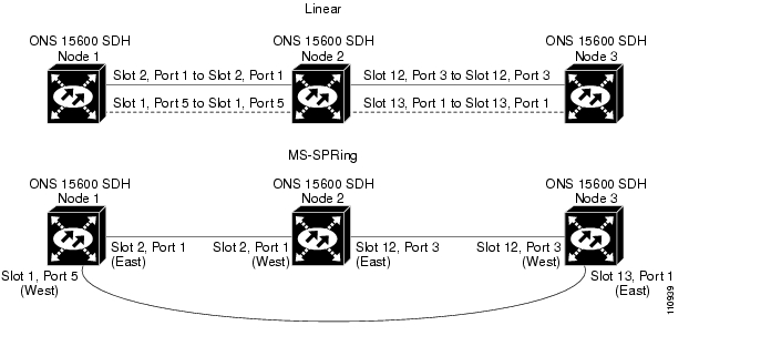
Figure 12-1 Linear ADM to MS-SPRing Conversion

Step11 Create the ring by connecting the protect fiber from one end node to the protect port on the other end node. For example, the fiber between Node 1/Slot 1/Port 5 and Node 2/Slot 1/Port 5 ( Figure12-1) can be rerouted to connect Node1/Slot 1/Port 5 to Node 3/Slot13/Port 1.


Note If you need to physically remove any STM-N cards, do so now. In this example, cards in Node2/Slots 1 and 13 can be removed. See the "NTP-F15 Remove and Replace a Card" procedure.


Step12 In network view, click the Circuits tabs and complete the "DLP-F66 Export CTC Data" task to save the circuit data to a file on your hard drive.

Step13 Complete the "DLP-F53 Provision SDH DCC Terminations" task at the end nodes to provision the slot in each node that is not already in the RS-DCC Terminations list.

Step14 For circuits provisioned on a VC4 that is now part of the protection bandwidth (VC4s 9 to 16 for an STM-16 MS-SPRing, and VC4s 33 to 64 for an STM-64 MS-SPRing), delete and recreate each circuit:


Note Deleting circuits is service affecting.


a. Complete the "DLP-E97 Delete Circuits" task  for one circuit.

b. Create the circuit on VC4s 1 to 8 for an STM-16 MS-SPRing, or 1 to 32 for an STM-64 MS-SPRing on the fiber that served as the protect fiber in the linear ADM. See the "NTP-F43 Create a Manually Routed Optical Circuit" procedure  for instructions.

c. Repeat Steps a  and b  for each circuit residing on an MS-SPRing protect VC4.

Step15 Complete the "NTP-F37 Create an MS-SPRing" procedure to put the nodes into an MS-SPRing.

Stop. You have completed this procedure.


DLP-F132 Verify that a 1+1 (LMSP) Working Port is Active

Purpose

This task verifies that a working slot in a 1+1 (LMSP) protection scheme is active (and that the protect slot is in standby).

Tools/Equipment

None

Prerequisite Procedures

F36 Log into CTC

Required/As Needed

As needed

Onsite/Remote

Both

Security Level

Maintenance or higher


Step1 In node view, click the Maintenance > Protection tabs.

Step2 In the Selected Group area, verify that the working slot/port is shown as Working/Active. If so, this task is complete.

Step3 If the working slot says Working/Standby, perform a Manual switch on the working port:

a. In the Selected Group area, choose the Protect/Active port.

a. In the Switch Commands field, choose Manual .

b. Click Yes in the confirmation dialog box.

Step4 Verify that the working slot is carrying traffic (Working/Active).


Note If the slot is not active, look for conditions or alarms that might be preventing the card from carrying working traffic. Refer to the CiscoONS15600SDH Troubleshooting Guide.


Step5 When the working port is carrying traffic, clear the Manual switch:

a. In the Switch Commands field, choose Clear .

b. Click Yes in the confirmation dialog box.

Step6 Verify that the working port does not revert to Standby, which might indicate a problem on the working span.

Step7 Return to your originating procedure (NTP).


NTP-F79 Convert a Point-to-Point or Linear ADM to an SNCP

Purpose

This procedure upgrades a point-to-point or Linear ADM to a subnetwork connection protection (SNCP).

Tools/Equipment

None

Prerequisite Procedures

F34 Provision a Point-to-Point Connection

Required/As Needed

As needed

Onsite/Remote

Onsite

Security Level

Provisioning or higher


Caution This procedure is service affecting. All circuits are deleted and reprovisioned.


Step1 Complete the "DLP-F36 Log into CTC" task at a node on the point-to-point or linear ADM. If you are already logged in, continue with Step 2.

Step2 Complete the "DLP-F131 Check the Network for Alarms and Conditions" task.

Step3 Complete the "DLP-F132 Verify that a 1+1 (LMSP) Working Port is Active" task for each node.

Step4 Complete the "DLP-F117 Delete a 1+1 Protection Group" task for each 1+1 protection group that supports the point-to-point or linear ADM span.

Step5 Complete the "DLP-F53 Provision SDH DCC Terminations" task at the protect cards in all nodes.

Step6 Complete the "DLP-E97 Delete Circuits" task and the "NTP-F42 Create an Automatically Routed Optical Circuit" procedure to delete and recreate the circuits one at a time.

Step7 Complete the "NTP-F39 Provision SNCP Nodes" procedure.

Stop. You have completed this procedure.


NTP-F80 Convert an SNCP to a Two-Fiber MS-SPRing

Purpose

This procedure converts an SNCP to a two-fiber MS-SPRing.

Tools/Equipment

None

Prerequisite Procedures

F39 Provision SNCP Nodes

Required/As Needed

As needed

Onsite/Remote

Both

Security Level

Provisioning or higher


Caution This procedure is service affecting. All circuits on the ring are deleted and reprovisioned.


Caution Read through this procedure completely before beginning the conversion.


Note Before beginning this procedure, you should have a unique ring ID number to identify the new MS-SPRing and a unique node ID number for each node on the ring.


Note Before beginning this procedure, optical transmit and receive levels should be in their acceptable range as shown in the specifications section for each card in the CiscoONS15600SDH Reference Manual.


Step1 Complete the "DLP-F36 Log into CTC" task at an ONS15600SDH on the network where you will begin the ring conversion. If you are already logged in, continue with Step 2.

Step2 Complete the "DLP-F131 Check the Network for Alarms and Conditions" task.

Step3 In network view, right-click a span adjacent to the node you are logged into.

Step4 From the shortcut menu, choose Circuits . The Circuits on Span window appears.

Step5 Verify that the total number of active VC4 circuits does not exceed 50 percent of the span bandwidth. In the Circuits column there is a block titled "Unused." This number should exceed 50 percent of the span bandwidth.


Note If the span is an STM-16, no more than 8 VC4s can be provisioned on the span. If the span is an STM-64, no more than 32 VC4s can be provisioned on the span.


Caution If the first half of the capacity is exceeded, this procedure cannot be completed. Bandwidth must be 50percent unassigned to convert to MS-SPRing. Refer to local procedures for relocating circuits if these requirements are not met.


Step6 Repeat Steps 3 through 5 for each span in the SNCP that you will convert to the MS-SPRing. If all nodes comply with Step5, continue with Step7.

Step7 Save the circuit information:

a. In network view, click the Circuits > Circuits tabs.

b. Record the circuit information using one of the following tasks:

From the File menu, choose Print to print the circuits table.

Complete the "DLP-F66 Export CTC Data" task .

Step8 Delete the circuits:


Note This method uses the network view. To delete circuits one at a time from each node, see the "DLP-E97 Delete Circuits" task.


a. In network view, click the Circuits tab. All circuits on the ring appear.

b. Press Shift and click each circuit in the display. Each line in the display turns dark blue as it is selected.

c. After you have selected the circuits, click Delete . Allow several minutes for processing; the actual length of time depends on the number of circuits in the network.

Step9 Complete the "NTP-F37 Create an MS-SPRing" procedure.

Step10 To recreate the circuits, see "Create Circuits" and choose the applicable procedure for the circuit type you want to enter.

Stop. You have completed this procedure.


NTP-F81 Modify an MS-SPRing

Purpose

This procedure changes an MS-SPRing ring ID, node ID, or ring and span reversion times.

Tools/Equipment

None

Prerequisite Procedures

F37 Create an MS-SPRing

Required/As Needed

As needed

Onsite/Remote

Onsite or remote

Security Level

Provisioning or higher


Step1 Complete the "DLP-F36 Log into CTC" task at a node in the MS-SPRing you want to modify. If you are already logged in, continue with Step 2.

Step2 Check the MS-SPRing for outstanding alarms and conditions. See the "DLP-F131 Check the Network for Alarms and Conditions" task for instructions.


Note Some or all of the following alarms appear during MS-SPRing setup: E-W MISMATCH, RING MISMATCH, APSCIMP, APSDFLTK, and MS-SPRingOSYNC. The alarms clear after you configure all the nodes in the MS-SPRing. For definitions of these alarms, see the CiscoONS15600SDH Troubleshooting Guide.


Step3 To change the MS-SPRing ring ID or the ring or span reversion times, complete the following steps. If you want to change a node ID, continue with Step4.

a. In network view, click the Provisioning > MS-SPRing tabs.

b. Click the MS-SPRing you want to modify and click Edit .

c. In the MS-SPRing window, change any of the following:

Ring ID—If needed, change the MS-SPRing ring ID (a number between 0 and 9999). Do not choose a number that is already assigned to another MS-SPRing.

Reversion time—If needed, change the amount of time that will pass before the traffic reverts to the original working path after a ring switch.

d. Click Apply .

If you changed the ring ID, the MS-SPRing window closes automatically. If you only changed a reversion time, close the window by choosing Close from the File menu.

Step4 To change an MS-SPRing node ID, complete the following steps; otherwise, proceed to Step5.

a. On the network map, double-click the node with the node ID you want to change.

b. Click the Provisioning > MS-SPRing tabs.

c. Choose a Node ID number. Do not choose a number already assigned to another node in the same MS-SPRing.

d. Click Apply.

Step5 Verify the following:

A green span line appears between all MS-SPRing nodes.

All E-W MISMATCH, RING MISMATCH, APSCIMP, DFLTK, MS-SPRingOSYNC, and Node ID Mismatch alarms are cleared.


Note For definitions of these alarms, see the CiscoONS15600SDH Troubleshooting Guide.


Stop. You have completed this procedure.


NTP-F82 Manage MS-SPRing Manual Ring Switches

Purpose

This procedure initiates or clears an MS-SPRing manual ring switch.

Tools/Equipment

None

Prerequisite Procedures

F37 Create an MS-SPRing

Required/As Needed

As needed

Onsite/Remote

Onsite or remote

Security Level

Provisioning or higher


Step1 Complete the "DLP-F36 Log into CTC" task at a node in the MS-SPRing where you want to initiate the Manual ring switch. If you are already logged in, continue with Step 2.

Step2 As needed, complete the "DLP-F133 Initiate an MS-SPRing Manual Ring Switch" task.

Step3 As needed, complete the "DLP-F134 Clear an MS-SPRing Manual Ring Switch" task.

Stop. You have completed this procedure.


DLP-F133 Initiate an MS-SPRing Manual Ring Switch

Purpose

This task initiates an MS-SPRing manual ring switch.

Tools/Equipment

None

Prerequisite Procedures

F36 Log into CTC

Required/As Needed

As needed

Onsite/Remote

Onsite

Security Level

Provisioning or higher


Step1 From the View menu, choose Go To Network View .

Step2 Click the Provisioning > MS-SPRing tabs.

Step3 Choose the MS-SPRing and click Edit .


Tip To move an icon to a new location, for example, to see MS-SPRing channel (port) information more clearly, click an icon, press Ctrl , and drag and drop it in a new location.


Step4 Right-click any MS-SPRing node channel (port) and choose Set West Protection Operation (if you chose a west channel) or Set East Protection Operation (if you chose an east channel).


Note For two-fiber MS-SPRings, the squares on the node icons represent the MS-SPRing working and protect channels. You can right-click either channel.


Step5 In the Set West Protection Operation dialog box or the Set East Protection Operation dialog box, choose MANUAL RING from the drop-down menu. Click OK .

Step6 Click Yes in the two Confirm MS-SPRing Operation dialog boxes.

Step7 Verify that the channel (port) displays the letter "M" for manual ring. Also verify that the span lines between the nodes where the manual switch was invoked turn purple, and that the span lines between all other nodes turn green on the network view map. This confirms the manual switch.

Step8 From the File menu, choose Close .

Step9 Return to your originating procedure (NTP).


DLP-F134 Clear an MS-SPRing Manual Ring Switch

Purpose

This task clears a manual ring switch.

Tools/Equipment

None

Prerequisite Procedures

F36 Log into CTC

Required/As Needed

As needed

Onsite/Remote

Onsite

Security Level

Provisioning or higher


Step1 From the View menu, choose Go To Network View .

Step2 Click the Provisioning > MS-SPRing tabs.

Step3 Choose the MS-SPRing and click Edit .


Tip To move an icon to a new location, for example, to see MS-SPRing channel (port) information more clearly, click an icon on the Edit MS-SPRing network graphic and press Ctrl while you drag and drop the icon to a new location.


Step4 Right-click the MS-SPRing node channel (port) where the manual ring switch was applied and choose SetWest Protection Operation or Set East Protection Operation, as applicable.

Step5 In the dialog box, choose CLEAR from the drop-down menu. Click OK .

Step6 Click Yes in the Confirm MS-SPRing Operation dialog box. The letter "M" is removed from the channel (port) and the span turns green on the network view map.

Step7 From the File menu, choose Close .

Step8 Return to your originating procedure (NTP).


hometocprevnextglossaryfeedbacksearchhelp

Posted: Thu Feb 26 17:32:11 PST 2004
All contents are Copyright © 1992--2004 Cisco Systems, Inc. All rights reserved.
Important Notices and Privacy Statement.