cc/td/doc/product/ong/600_sdh/sdh60014
hometocprevnextglossaryfeedbacksearchhelp
PDF

Table Of Contents

Create Circuits

Before You Begin

F60 Assign a Name to a Port

F61 Provision SNCP Selectors During Circuit Creation

F62 Provision an Optical Circuit Source and Destination

F63 Provision an Optical Circuit Route

F64 Provision a Half Circuit Source and Destination—MS-SPRing and 1+1 (LMSP)

F65 Provision a Half Circuit Source and Destination—SNCP

Create Circuits


This chapter explains how to create CiscoONS15600SDH circuits. For additional information, refer to the Circuits chapter in the CiscoONS15600SDH Reference Manual.


Note The Software Release 1.4 does not support a full state model. As a result, the circuit state cannot be changed; it is always In Service (IS).


Before You Begin

Before performing any of the following procedures, investigate all alarms and clear any trouble conditions. Refer to the CiscoONS15600SDH Troubleshooting Guide as necessary.

This section lists the chapter procedures (NTPs). Turn to a procedure for a list of its tasks (DLPs).

1. F41 Verify Network Turn Up—Complete this procedure before you create any circuits.

2. F42 Create an Automatically Routed Optical Circuit—Complete as needed.

3. F43 Create a Manually Routed Optical Circuit—Complete as needed.

4. F44 Create a Unidirectional Optical Circuit with Multiple Drops—Complete this procedure as needed.

5. F45 Test Optical Circuits—Complete this procedure after you create circuits.

6. F46 Create a Half Circuit on an MS-SPRing or 1+1 (LMSP) Node—Complete this procedure as needed to create a half circuit using an STM-N as a destination in an multiplex section-shared protection ring (MS-SPRing) or 1+1 (LMSP) topology.

7. F47 Create a Half Circuit on an SNCP Node—Complete as needed to create a half circuit using an STM-N as a destination in a subnetwork connection protection (SNCP) node.

8. F48 Create a DCC Tunnel—Complete as needed.


Note To provision ONS15600SDH circuits from an ONS 15454 SDH node, the Cisco Transport Controller (CTC) version launched must be compatible with or higher than the ONS15600SDH CTC version.


Note In this chapter, "cross-connect" and "circuit" have the following meanings: cross-connect refers to the connections that occur within a single node to allow a circuit to enter and exit the node. Circuit refers to the series of connections from a traffic source (where traffic enters the network) to the drop or destination (where traffic exits the network).


Note You cannot set up low-order circuits to terminate on an ONS15600SDH node. However, you can create both high-order and low-order circuits that have an ONS 15454 SDH source and destination with an ONS15600SDH as a pass-through node. When creating a low-order path circuits between ONS15454SDH nodes, a VC4 tunnel is necessary. The VC4 tunnel can be created automatically by using the Circuit Creation wizard to create the low-order circuit, or manually by using the Circuit Creation wizard to create the VC4 tunnel before creating the low-order circuit. When you create VC4 tunnels over ONS 15600 pass-through nodes manually, you have control over how the tunnel is created. For information about low-order circuit creation and tunneling, refer to the circuit chapters in the Cisco ONS 15454 SDH Procedure Guide.


Note During circuit provisioning in a network that includes ONS 15600s and ONS 15454s, the ONS15600SDH raises a temporary UNEQ-P alarm. The alarm clears when the circuit is complete.


Table6-1 defines key ONS15600SDH circuit creation terms and options.

Table 6-1 Key ONS 15600 SDH Circuit Options

Circuit Option
Description

Source

The point where the circuit enters the ONS15600SDH network. The first facility specified when creating a connection is also considered the source.

Destination

The point where the circuit exits an ONS15600SDH network. The last facility specified when creating a connection is also considered the destination.

Automatic circuit routing

CTC routes the circuit automatically on the shortest available path based on the routing parameters that you define and on bandwidth availability.

Manual circuit routing

Allows you to choose a specific path, not just the shortest path chosen by automatic routing. You can choose a specific virtual channel (VC) for each circuit segment, and you can create circuits from work orders prepared by an operations support system (OSS) like the Telcordia TIRKS system.


NTP-F41 Verify Network Turn Up

Purpose

This procedure verifies that the ONS15600SDH network is ready for circuit provisioning.

Tools/Equipment

None

Prerequisite Procedures

"Turn Up Network"

Required/As Needed

Required

Onsite/Remote

Onsite or remote

Security Level

Provisioning or higher


Step1 Complete the "DLP-F36 Log into CTC" task at a node on the network where you will create circuits. If you are already logged in, continue with Step2.

Step2 From the View menu, choose Go To Network View . Wait for all the nodes that are part of the network to appear on the network map. (Large networks might take several minutes to display all the nodes.)


Note If this is the first time your computer has connected to this ONS15600SDH network, the node icons will be stacked on the left side of the graphic area, possibly out of view. Use the scroll bar below the network map to display the icons. To separate the icons, press Ctrl and drag and drop the icon to the new location. Repeat until all the nodes are visible on the graphic area.


Step3 Verify node accessibility. All node icons must be either green, yellow, orange, or red.

If all network nodes do not appear after a few minutes, or if a node icon is gray with an IP address beneath it, do not continue. Look at the NET box in the lower right corner of the window. If it is gray, log in again, making sure not to check the Disable Network Discovery check box on the CTC Login dialog box. If problems persist, see "Turn Up Network"  to review the network turn-up procedure appropriate for your network topology, or refer to the Cisco ONS 15600 SDH Troubleshooting Guide for troubleshooting procedures.

Step4 Verify data communications channel (DCC) connectivity. All nodes must be connected by green lines. If lines are missing or gray, do not continue. See "Turn Up Network" and follow the network turn-up procedure appropriate for your network topology. Verify that all nodes have DCC connectivity before continuing.

Step5 Click the Alarms tab to view alarm descriptions. Investigate and resolve, if necessary, all critical (red node icon) or major (orange node icon) alarms. Refer to the CiscoONS15600SDH Troubleshooting Guide to resolve alarms before continuing.

Step6 From the View menu, choose Go To Home View . Verify that the node is provisioned according to your site or engineering plan:

a. View the cards displayed in the shelf map. Verify that the ONS 15600 SDH cards appear in the specified slots.

b. Click the Provisioning > General tabs. Verify that the node name, contacts, date, time, and Simple Network Time Protocol (SNTP) server IP address (if used) are correctly provisioned. If needed, make corrections using the "NTP-F24 Set Up Date, Time, and Contact Information" procedure on page 4-6 .

c. Click the Network tab. Verify that the IP address, Subnet Mask, Default Router, and Gateway Settings are correctly provisioned. If not, make corrections using the "NTP-F25 Set Up CTC Network Access" procedure on page 4-8 .

d. Click the Protection tab. Verify that protection groups are created as specified in your site plan. If the protection groups are not created, complete the "NTP-F27 Create a 1+1 (LMSP) Protection Group" procedure on page 4-19 .

e. If the node is in an MS-SPRing, click the MS-SPRing tab. (If the node is not in an MS-SPRing, continue with Step f .) Verify that the following items are provisioned as specified in your site plan:

MS-SPRing type (2-Fiber)

MS-SPRing ring ID and node IDs

Ring reversion time

East and west card assignments

If you need to make corrections, see the "NTP-F36 Provision MS-SPRing Nodes" procedure  for instructions.

f. Click the Security tab. Verify that the users and access levels are provisioned as specified. If not, see the "NTP-F23 Create Users and Assign Security" procedure on page 4-4  to correct the information.

g. If SNMP is used, click the SNMP tab and verify the trap and destination information. If the information is not correct, see the "NTP-F28 Set Up SNMP" procedure on page 4-21  to correct the information.

h. Click the DCC/GCC tab. Verify that DCCs were created to the applicable STM-N cards and ports. If DCCs were not created for the appropriate STM-N cards and ports, go to the "DLP-F53 Provision SDH DCC Terminations" task .

i. Click the Timing tab. Verify that timing is provisioned as specified. If not, go to the "NTP-F72 Change Node Timing" procedure  to make the changes.

j. Click the Alarm Behavior tab. If you provisioned optional alarm profiles, verify that the alarms are provisioned as specified. If not, see the "NTP-F56 Create, Assign, and Delete Alarm Severity Profiles" procedure  to change the information.

Step7 Repeat Step6 for each node in the network.

Step8 As appropriate, complete circuit creation procedures listed below:

F42 Create an Automatically Routed Optical Circuit 

F43 Create a Manually Routed Optical Circuit 

F44 Create a Unidirectional Optical Circuit with Multiple Drops 

F46 Create a Half Circuit on an MS-SPRing or 1+1 (LMSP) Node 

F47 Create a Half Circuit on an SNCP Node 

Stop. You have completed this procedure.


NTP-F42 Create an Automatically Routed Optical Circuit

Purpose

This procedure creates an automatically routed optical circuit, including VC4 and concatenated VC4-2c, VC4-3c, VC4-4c, VC4-8c, VC4-16c, or VC4-64c speeds. CTC automatically routes the circuit based on entries you make at circuit creation and the system load.

Tools/Equipment

None

Prerequisite Procedures

F41 Verify Network Turn Up

Required/As Needed

As needed

Onsite/Remote

Onsite or remote

Security Level

Provisioning or higher


Step1 Complete the "DLP-F36 Log into CTC" task at a node on the network where you will create the high-order circuit. The default (node) view appears. If you are already logged in, continue with Step2.

Step2 If you want to assign a name to the tunnel source and destination ports before you create the circuit, complete the "DLP-F60 Assign a Name to a Port" task. If not, continue with Step3.

Step3 From the View menu, choose Go To Network View .

Step4 Click the Circuits tab, then click Create .

Step5 In the Circuit Creation dialog box ( Figure6-1), complete the following fields:

Name—Assign a name to the circuit. The name can be alphanumeric and up to 48 characters (including spaces). Circuit names should be 44 characters or less if you want the ability to create monitor circuits. If you leave the field blank, CTC assigns a default name to the circuit.

Type—Choose VC_HO_PATH_CIRCUIT .

Size—Choose the circuit size: VC4, VC4-2c, VC4-3c, VC4-4c, VC4-8c, VC4-16c, or VC4-64c.

Bidirectional—When checked (default), creates a two-way circuit. Leave checked for this circuit.

Number of circuits—Type the number of circuits you want to create. The default is 1. If you are creating multiple circuits with the same source and destination, you can use autoranging to create the circuits automatically.

Auto-ranged—This box is automatically checked when you enter more than 1 in the Number of circuits field. Leave this box checked if you are creating multiple optical circuits with the same source and destination and you want CTC to create the circuits automatically. Uncheck the box if you do not want CTC to create the circuits automatically.

State—Choose IS (CTC displays only in-service circuits).

Apply to drop ports—Check this box if you want to apply the state chosen in the State field to the circuit source and destination ports. CTC will apply the circuit state to the ports only if the circuit bandwidth is the same as the port bandwidth or, if the port bandwidth is larger than the circuit, the circuit must be the first circuit to use the drop port. If not, a Warning dialog box displays the ports where the circuit state could not be applied. If the box is unchecked, CTC will not change the state of the source and destination ports.


Note Loss of Signal (LOS) alarms appear if in service (IS) ports are not receiving signals.


Inter-domain (UCP) SLA—Future use.

Protected Drops—Check this box if you want CTC to display only protected cards and ports (1+1 protection) as choices for the circuit source and destination.

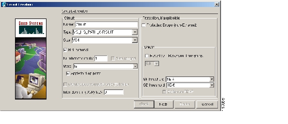
Figure 6-1 Creating a Circuit

Step6 If the circuit will be routed on an SNCP, complete the "DLP-F61 Provision SNCP Selectors During Circuit Creation" task.

Step7 Click Next .

Step8 Complete the "DLP-F62 Provision an Optical Circuit Source and Destination" task for the optical circuit that you are creating.

Step9 In the Circuit Routing Preferences area ( Figure6-2), check Route Automatically . Two options are available; choose either, both, or none based on your preferences.

Using Required Nodes/Spans—Check this box to specify nodes and spans to include or exclude in the CTC-generated circuit route.

Review Route Before Creation—Check this box to review and edit the circuit route before the circuit is created.

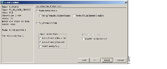
Figure 6-2 Setting Circuit Routing Preferences

Step10 Set the circuit path protection:

To route the circuit on a protected path, leave Fully Protected Path checked and continue with Step 11 . CTC creates a fully protected circuit route based on the path diversity option you choose. Fully protected paths might or might not have SNCP path segments (with primary and alternate paths), and the path diversity options apply only to SNCP path segments, if any exist.

To create an unprotected circuit, uncheck Fully Protected Path and continue with Step 12 .

To route the circuit on an MS-SPRing protection channel, if available, uncheck Fully Protected Path , check Protection Channel Access , click Yes in the Warning dialog box, and then continue with Step 12 .


Caution Circuits routed on MS-SPRing protection channels are not protected. They are preempted during MS-SPRing switches.


Step11 If you selected Fully Protected Path, choose one of the following:

Nodal Diversity Required—Ensures that the primary and alternate paths within SNCP portions of the complete circuit path are nodally diverse.

Nodal Diversity Desired—Specifies that node diversity is preferred, but if node diversity is not possible, CTC creates fiber-diverse paths for the SNCP portion of the complete circuit path.

Link Diversity Only—Specifies that only fiber-diverse primary and alternate paths for SNCP portions of the complete circuit path are needed. The paths might be node-diverse, but CTC does not check for node diversity.

Step12 If you selected Using Required Nodes/Spans in Step9, complete the following substeps; otherwise, proceed to Step13:

a. Click Next .

b. In the Circuit Route Constraints area, click a node or span on the circuit map.

c. Click Include to include the node or span in the circuit, or click Exclude to exclude the node or span from the circuit. The order in which you select included nodes and spans sets the circuit sequence. Click spans twice to change the circuit direction.

d. Repeat Step c  for each node or span you wish to include or exclude.

e. Review the circuit route. To change the circuit routing order, select a node beneath the Required Nodes/Lines or Excluded Nodes Links lists, then click the Up or Down buttons to change the circuit routing order. Click Remove to remove a node or span.

Step13 If you selected Review Route Before Creation in Step9, complete the following substeps; otherwise, proceed to Step14:

a. Click Next .

b. Review the circuit route. To add or delete a circuit span, select a node on the circuit route. Blue arrows show the circuit route. Green arrows indicate spans that you can add. Click a span arrowhead, then click Include to include the span or Remove to remove the span.

c. If the provisioned circuit does not reflect the routing and configuration you want, click Back to verify and change circuit information. If the circuit needs to be routed to a different path, see the "NTP-F43 Create a Manually Routed Optical Circuit" procedure  to assign the circuit route yourself.

Step14 Click Finish. One of the following occurs, based on the circuit properties you provisioned in the Circuit Creation dialog box:

If you entered more than 1 in Number of Circuits and checked Auto-ranged, CTC automatically creates the number of circuits entered in Number of Circuits. If autoranging cannot complete all the circuits (for example, not enough bandwidth is available on the source or destination), a dialog box appears. Set the new source or destination for the remaining circuits, then click Finish to continue autoranging.

If you entered more than 1 in Number of Circuits and did not check Auto-ranged, the Circuit Creation dialog box appears so you can create the remaining circuits. Repeat Steps  5  through  13  for each additional circuit.

After completing the circuit(s), the Circuits window appears.

Step15 In the Circuits window, verify that the circuit(s) just created appear in the circuits list.

Step16 Complete the "NTP-F45 Test Optical Circuits" procedure. Skip this step if you built a test circuit.

Stop. You have completed this procedure.


DLP-F60 Assign a Name to a Port

Purpose

This task assigns a name to a port on any ONS15600SDH card.

Tools/Equipment

None

Prerequisite Procedures

F36 Log into CTC

NTP-F22 Verify Card Installation, page 4-2

Required/As Needed

As needed

Onsite/Remote

Onsite or remote

Security Level

Provisioning or higher


Step1 Double-click the card that has the port you want to provision.

Step2 Click the Provisioning tab.

Step3 Click the Port Name column for the port number you are assigning a name to and enter the desired port name.

The port name can be up to 32 alphanumeric/special characters and is blank by default.

Step4 Click Apply .

Step5 Return to your originating procedure (NTP).


DLP-F61 Provision SNCP Selectors During Circuit Creation

Purpose

This task provisions SNCP selectors during circuit creation. Use this task only if the circuit will be routed on an SNCP.

Tools/Equipment

None

Prerequisite Procedures

You must have the Circuit Creation wizard displayed.

Required/As Needed

As needed

Onsite/Remote

Onsite or remote

Security Level

Provisioning or higher


Step1 In the Circuit Attributes area of the Circuit Creation wizard, set the SNCP path selectors:

Revertive—Check this box if you want traffic to revert to the working path when the conditions that diverted it to the protect path are repaired. If you do not choose Revertive, traffic remains on the protect path after the switch.

Reversion time—If Revertive is checked, click the Reversion time field and choose a reversion time from the drop-down menu. The range is 0.5 to 12.0 minutes. The default is 5.0 minutes. This is the amount of time that will elapse before the traffic reverts to the working path. Traffic can revert when conditions causing the switch are cleared.

SF threshold—For high-order VC circuits, set the SNCP path-level signal failure bit error rate (BER) thresholds.

SD threshold—For high-order VC circuits, set the SNCP path-level signal degrade BER thresholds.

Switch on PDI-P—Not enabled for ONS 15600 SDH.

Step2 Return to your originating procedure (NTP).


DLP-F62 Provision an Optical Circuit Source and Destination

Purpose

This task provisions the source and destination cards for an optical circuit.

Tools/Equipment

None

Prerequisite Procedures

Perform this task during one of the following procedures:

F42 Create an Automatically Routed Optical Circuit

F43 Create a Manually Routed Optical Circuit

F44 Create a Unidirectional Optical Circuit with Multiple Drops

Required/As Needed

As needed

Onsite/Remote

Onsite or remote

Security Level

Provisioning or higher


Step1 From the Node drop-down menu, choose the node where the circuit will originate.

Step2 From the Slot drop-down menu, choose the slot containing the optical card where the circuit originates. (If a card's capacity is fully utilized, it does not appear in the menu.)

Step3 Choose the source port from the Port drop-down menu.

Step4 Choose the VC from the VC drop-down menu. VCs do not appear if they are already in use by other circuits.


Note The VCs that appear depend on the card, circuit size, and protection scheme.


Step5 If you need to create a secondary source, for example, an SNCP bridge/selector circuit entry point in a multivendor SNCP, click Use Secondary Source and repeat Steps 1 through 3 to define the secondary source.

Step6 Click Next.

Step7 From the Node drop-down menu, choose the destination node.

Step8 From the Slot drop-down menu, choose the slot containing the optical card where the circuit will terminate (destination card). (If a card's capacity is fully utilized, the card does not appear in the menu.)

Step9 Choose the destination port from the Port drop-down menu.

Step10 Choose the VC from the VC drop-down menu. VCs do not appear if they are already in use by other circuits.


Note The VCs that appear depend on the card, circuit size, and protection scheme.


Step11 If you need to create a secondary destination, for example, an SNCP bridge/selector circuit entry point in a multivendor SNCP, click Use Secondary Destination and repeat Steps 7 through 10 to define the secondary destination.

Step12 Click Next .

Step13 Return to your originating procedure (NTP).


DLP-F63 Provision an Optical Circuit Route

Purpose

This task provisions an optical circuit route for manually routed circuits.

Tools/Equipment

None

Prerequisite Procedures

Perform this task during one of the following procedures:

F42 Create an Automatically Routed Optical Circuit

F43 Create a Manually Routed Optical Circuit

F44 Create a Unidirectional Optical Circuit with Multiple Drops

Required/As Needed

As needed

Onsite/Remote

Onsite or remote

Security Level

Provisioning or higher


Step1 In the Route Review and Edit area of the Circuit Creation wizard, click the source node icon if it is not already selected.

Step2 Click the arrowhead of the span you want the circuit to travel. The arrow turns white. In the Selected Span area, the From and To fields display span information. The source VC4 appears in the Source VC4 field.

Step3 If you want to change the source VC4, adjust it in the Source VC4 field, otherwise go to Step4.

Step4 Click Add Span. The span is added to the Included Spans list and the span arrow turns blue.

Step5 Repeat Steps 2 through 4 until the circuit is provisioned from the source to the destination node through all intermediary nodes. If Fully Protect Path is checked on the Circuit Routing Preferences panel, you must:

Add two spans for all SNCP or unprotected portions of the circuit route from the source to the destination

Add one span for all MS-SPRing or 1+1 portions of route from the source to the destination

Step6 Return to your originating procedure (NTP).


NTP-F43 Create a Manually Routed Optical Circuit

Purpose

This procedure creates a manually routed, bidirectional or unidirectional optical circuit, including VC4 and concatenated VC4-2c, VC4-3c, VC4-4c, VC4-8c, VC4-16c, or VC4-64c speeds.

Tools/Equipment

None

Prerequisite Procedures

F41 Verify Network Turn Up

Required/As Needed

As needed

Onsite/Remote

Onsite or remote

Security Level

Provisioning or higher


Step1 Complete the "DLP-F36 Log into CTC" task at a node on the network where you want to create an optical circuit. If you are already logged in, continue with Step2.

Step2 If you want to assign a name to the tunnel source and destination ports before you create the circuit, complete the "DLP-F60 Assign a Name to a Port" task. If not, continue with Step3.

Step3 From the View menu, choose Go To Network View .

Step4 Click the Circuits tab, then click Create .

Step5 In the Circuit Creation dialog box ( Figure6-2), complete the following fields:

Name—Assign a name to the circuit. The name can be alphanumeric and up to 48 characters (including spaces). Circuit names should be 44 characters or less if you want the ability to create monitor circuits. If you leave the field blank, CTC assigns a default name to the circuit.

Type—Choose VC_HO_PATH_CIRCUIT .

Size—Choose the circuit size: VC4, VC4-2c, VC4-3c, VC4-4c, VC4-8c, VC4-16c, or VC4-64c.

Bidirectional—Leave checked (default) for this circuit. When checked, CTC creates a two-way circuit.

Number of circuits—Type the number of circuits that you want to create. The default is 1.

Auto-ranged—Applies to automatically routed circuits only. If you entered more than 1 in the Number of Circuits field, uncheck this box. (The box is unavailable if only one circuit is entered in Number of Circuits.)

State—Choose IS (CTC displays only in-service circuits).

Apply to drop ports—Check this box if you want to apply the state chosen in the State field to the circuit source and destination ports. CTC will apply the circuit state to the ports only if the circuit bandwidth is the same as the port bandwidth or, if the port bandwidth is larger than the circuit, the circuit must be the first circuit to use the drop port. If not, a Warning dialog box displays the ports where the circuit state could not be applied. If the box is unchecked, CTC will not change the state of the source and destination ports.


Note Loss LOS alarms appear if IS ports are not receiving signals.


Inter-domain (UCP) SLA—Future use.

Protected Drops—If selected, CTC displays only protected cards and ports (1+1 protection) as choices for the circuit source and destination.

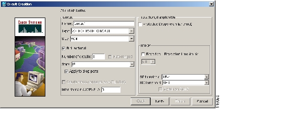
Figure 6-3 Creating a Circuit

Step6 If the circuit will be routed on an SNCP, complete the "DLP-F61 Provision SNCP Selectors During Circuit Creation" task.

Step7 Click Next .

Step8 Complete the "DLP-F62 Provision an Optical Circuit Source and Destination" task for the optical circuit you are creating.

Step9 In the Circuit Routing Preferences area ( Figure6-2), uncheck Route Automatically .

Step10 Set the circuit path protection:

To route the circuit on a protected path, leave Fully Protected Path checked and continue with Step 11 .

To create an unprotected circuit, uncheck Fully Protected Path and continue with Step 12 .

To route the circuit on an MS-SPRing protection channel, if available, uncheck Fully Protected Path , check Protection Channel Access , click Yes in the Warning dialog box, then continue with Step 12 .


Caution Circuits routed on MS-SPRing protection channels are not protected and are preempted during MS-SPRing switches.


Step11 If you selected Fully Protected Path, choose one of the following:

Nodal Diversity Required—Ensures that the primary and alternate paths within the SNCP portions of the complete circuit path are nodally diverse.

Nodal Diversity Desired—Specifies that node diversity is preferred, but if node diversity is not possible, CTC creates fiber-diverse paths for the SNCP portion of the complete circuit path.

Link Diversity Only—Specifies that only fiber-diverse primary and alternate paths for SNCP portions of the complete circuit path are needed. The paths might be node-diverse, but CTC does not check for node diversity.

Step12 Click Next . In the Route Review and Edit area, node icons appear for you to route the circuit manually. The green arrows pointing from the source node to other network nodes indicate spans that are available for routing the circuit.

Step13 Complete the "DLP-F63 Provision an Optical Circuit Route" task.

Step14 Click Finish. If the path does not meet the specified path diversity requirement, an error message appears and allows you to change the circuit path. If you entered more than 1 in the Number of circuits field, the Circuit Creation dialog box appears after the circuit is created so you can create the remaining circuits.

Step15 Repeat Steps 5 through 14 for each additional circuit.

When provisioning a protected circuit, you only need to select one path of 1+1 spans from the source to the drop. If you select unprotected spans as part of the path, select two different paths for the unprotected segment of the path.

Step16 When all the circuits are created, the main Circuits window appears. Verify that the circuit(s) you created appear in the window.

Step17 Complete the "NTP-F45 Test Optical Circuits" procedure.

Stop. You have completed this procedure.


NTP-F44 Create a Unidirectional Optical Circuit with Multiple Drops

Purpose

This procedure creates a unidirectional STM-N circuit with multiple traffic drops (circuit destinations). The ONS15600SDH supports up to 2048 1:2 nonblocking broadcast connections or up to 682 1:N (where N is less than or equal to 8) nonblocking broadcast connections.

Tools/Equipment

None

Prerequisite Procedures

F41 Verify Network Turn Up

Required/As Needed

As needed

Onsite/Remote

Onsite or remote

Security Level

Provisioning or higher


Step1 Complete the "DLP-F36 Log into CTC" task at a node on the network where you will create the optical circuit. If you are already logged in, continue with Step2.

Step2 If you want to assign a name to the tunnel source and destination ports before you create the circuit, complete the "DLP-F60 Assign a Name to a Port" task. If not, continue with Step3.

Step3 From the View menu, choose Go To Network View .

Step4 Click the Circuits tab, then click Create .

Step5 In the Circuit Creation dialog box, complete the following fields:

Name—Assign a name to the circuit. The name can be alphanumeric and up to 48 characters (including spaces). Circuit names should be 44 characters or less if you want the ability to create monitor circuits. If you leave the field blank, CTC assigns a default name to the circuit.

Type—Choose VC_HO_PATH_CIRCUIT .

Size—Choose the circuit size: VC4, VC4-2c, VC4-3c, VC4-4c, VC4-8c, VC4-16c, or VC4-64c.

Bidirectional—Uncheck this box for this circuit.

Number of circuits—Leave the default unchanged (1).

Auto-ranged—Unavailable when the Number of Circuits field is 1.

State—Choose IS (CTC displays only in-service circuits).

Apply to drop ports—Check this box if you want to apply the state chosen in the State field to the circuit source and destination ports. CTC will apply the circuit state to the ports only if the circuit bandwidth is the same as the port bandwidth or, if the port bandwidth is larger than the circuit, the circuit must be the first circuit to use the drop port. If not, a Warning dialog box displays the ports where the circuit state could not be applied. If the box is unchecked, CTC will not change the state of the source and destination ports.


Note LOS alarms appear if IS ports are not receiving signals.


Inter-domain (UCP) SLA—Future use.

Protected Drops—Check this box if you want the circuit routed to only protect drops. If you check this box, CTC displays only protected cards as source and destination choices.

Step6 If the circuit will be routed on an SNCP, complete the "DLP-F61 Provision SNCP Selectors During Circuit Creation" task.

Step7 Click Next .

Step8 Complete the "DLP-F62 Provision an Optical Circuit Source and Destination" task for the circuit you are creating.

Step9 In the Circuit Routing Preferences area, uncheck Route Automatically . When unchecked, Using Required Nodes/Spans and Review Route Before Circuit Creation check boxes are not available.

Step10 Set the circuit path protection:

To route the circuit on a protected path, leave Fully Protected Path checked and continue with Step 11 . Fully protected paths might or might not have SNCP path segments (with primary and alternate paths), and the path diversity options apply only to SNCP path segments, if any exist.

To create an unprotected circuit, uncheck Fully Protected Path and continue with Step 12 .

To route the circuit on an MS-SPRing protection channel, if available, uncheck Fully Protected Path , check Protection Channel Access , click Yes in the Warning dialog box, then continue with Step 12 .


Caution Circuits routed on MS-SPRing protection channels are not protected and are preempted during MS-SPRing switches.


Step11 If you selected Fully Protected Path, choose one of the following:

Nodal Diversity Required—Ensures that the primary and alternate paths within the SNCP portions of the complete circuit path are nodally diverse.

Nodal Diversity Desired—Specifies that node diversity is preferred, but if node diversity is not possible, CTC creates fiber-diverse paths for the SNCP portion of the complete circuit path.

Link Diversity Only—Specifies that only fiber-diverse primary and alternate paths for SNCP portions of the complete circuit path are needed. The paths might be node-diverse, but CTC does not check for node diversity.


Note For manually routed circuits, CTC checks your manually provisioned path against the path diversity option you choose. If the path does not meet the path diversity requirement that is specified, CTC displays an error message.


Step12 Click Next . In the Route Review and Edit area, node icons appear so you can route the circuit manually. The green arrows pointing from the selected node to other network nodes indicate spans that are available for routing the circuit.

Step13 Complete the "DLP-F63 Provision an Optical Circuit Route" task.


Note When provisioning a protected circuit, you only need to select one 1+1 span paths from the source to the drop. If you select unprotected spans as part of the path, you must provision both the working and protect paths.


Step14 Click Finish . After completing the circuit, the Circuits window appears.

Step15 In the Circuits window, click the circuit that you want to route to multiple drops. The Delete, Edit, and Search radio buttons become active.

Step16 Click Edit . The Edit Circuit window appears with the General tab selected. All nodes in the DCC network appear on the network. Circuit source and destination information appears under the source and destination nodes. To display a detailed view of the circuit, click Show Detailed Map . To move a node icon, press Ctrl while you drag and drop the icon to the new location.

Step17 In the Edit Circuit dialog box, click the Drops tab. A list of existing drops appears.

Step18 Click Create.

Step19 In the Define New Drop dialog box, define the new drop:

a. Node—Choose the target node for the circuit drop.

b. Slot—Choose the target card and slot.

c. Port, VC4—Choose the port and/or VC4 from the Port and VC4 drop-down menus. The choice in these menus depends on the card selected in Step b .

d. The routing preferences for the new drop will match those of the original circuit. However, if the original circuit was routed on a protected path, you can change the nodal diversity options: Required, Desired, Don't Care; Link Diverse only. See Step 11  for options descriptions.

e. Click OK . The new drop appears in the Drops list.

Step20 If you need to create additional drops on the circuit, repeat Steps 17 through 19.

Step21 Click Close . The Circuits window appears.

Step22 Verify that the new drops appear under the Destination column for the circuit you edited. If they do not appear, repeat Steps 18 through 21 while verifying that all options are provisioned correctly.

Step23 Complete the "NTP-F45 Test Optical Circuits" procedure.

Stop. You have completed this procedure.


NTP-F45 Test Optical Circuits

Purpose

This procedure tests the first optical circuit created on the source or destination port.

Tools/Equipment

Test set capable of optical speeds, appropriate fibers, and attenuators

Prerequisite Procedures

This procedure assumes you completed facility loopback tests to test the fibers and cables from the source and destination ONS15600SDHs to the fiber distribution panel or the DSX. If this has not been done, do so now. In addition, you must complete one of the following procedures:

F42 Create an Automatically Routed Optical Circuit or

F43 Create a Manually Routed Optical Circuit

Required/As Needed

Required

Onsite/Remote

Onsite

Security Level

Provisioning or higher


Caution You cannot disconnect fibers and connect test sets if the circuit is carrying traffic.


Step1 Complete the "DLP-F36 Log into CTC" task at the source node. If you are already logged in, continue with Step 2.

Step2 Set the circuit source port to Out of Service-Maintenance (OOS_MT):

a. Double-click the card with the port used in the circuit.

b. Click the Provisioning > MS tabs.

c. In the State column of the appropriate port, choose OOS_MT from the drop-down menu.

d. Click Apply .

Step3 Set the circuit destination port to OOS_MT:

a. From the View menu, choose Go To Network View .

b. Double-click the destination node.

c. Double-click the card with the port used in the circuit.

d. Click the Provisioning > MS tabs.

e. In the State column of the appropriate port, choose OOS_MT from the drop-down menu.

f. Click Apply .

g. Leave card view open.

Step4 Set up the loopback cable at the destination node:

a. Test the loopback cable by connecting one end to the test set transmit (Tx) port and the other end to the test receive (Rx) port. Use appropriate attenuation; for information about attenuation, refer to the test set manual. If the test set does not run error-free, check the cable for damage and check the test set to make sure it is set up correctly.

b. Install the loopback cable on the port you are testing. Connect the transmit (Tx) connector to the receive (Rx) connector of the port being tested.


Note Use an appropriately sized attenuator when connecting transmit ports to receive ports. On the long-reach optical cards (STM-16LH16Port1550 and the STM-64LH4Port1550), use a 15-dB attenuator; on the short-reach optical cards (STM-16SH16Port1310 and STM-64SH 4Port1310), use a 3-dB attenuator.


Step5 Set up the loopback cable at the source node:

a. Test the loopback cable by connecting one end to the test set Tx port and the other end to the test Rx port. Use appropriate attenuation; for more information, refer to the test set manual. If the test set does not run error-free, check the cable for damage and check the test set to make sure it is set up correctly.

b. At the source node attach the loopback cable to the port you are testing. Connect the test set to the circuit source port: Tx port of the test set to the circuit Rx port; test set Rx port to the circuit Tx port.


Note Use an appropriately sized attenuator when connecting transmit ports to receive ports. On the long-reach optical cards (STM-16LH16Port1550 and the STM-64LH4Port1550), use a 15-dB attenuator; on the short-reach optical cards (STM-16SH16Port1310 and STM-64SH 4Port1310), use a 3-dB attenuator.


Step6 Configure the test set for the source STM-16 or STM-64 ONS15600SDH card. For information about configuring your test set, consult your test set user guide.

Step7 Verify that the test set displays a clean signal. If a clean signal is not present, repeat Steps 1 through 6 to make sure you have configured the test set and cabling.

Step8 Inject errors from the test set. Verify that the errors appear at the source and destination nodes.

Step9 Clear the performance monitoring (PM) counts for the ports that you tested. See the "DLP-F88 Clear Selected PM Counts" task on page8-9 for instructions.

Step10 Perform protection switch testing appropriate to the SDH topology:

For MS-SPRings see the "DLP-F58 MS-SPRing Switch Test" task .

For SNCPs, see the "DLP-F59 SNCP Protection Switching Test" task .

Step11 Perform a bit error rate test (BERT) for 12 hours or according to site specification. For information about configuring your test set for BERT, see your test set user guide.

Step12 After the BERT is complete, print the results or save them to a disk for future reference. For information about printing or saving test results, see your test set user guide.

Step13 Set the circuit destination port to IS:

a. In card view for the destination node, click the Provisioning > MS tabs.

b. In the State column of the appropriate port, choose IS from the drop-down menu.

c. Click Apply .

Step14 Set the circuit source port to IS:

a. From the View menu, choose Go To Network View .

b. Double-click the source node.

c. Double-click the card with the port used in the circuit.

d. Click the Provisioning > MS tabs.

e. In the State column of the appropriate port, choose IS from the drop-down menu.

f. Click Apply .

Stop. You have completed this procedure.


NTP-F46 Create a Half Circuit on an MS-SPRing or 1+1 (LMSP) Node

Purpose

This procedure creates an STM-N circuit from a drop card to an STM-N trunk card on the same node in an MS-SPRing or 1+1 (LMSP) topology.

Tools/Equipment

None

Prerequisite Procedures

F41 Verify Network Turn Up

Required/As Needed

As needed

Onsite/Remote

Onsite or remote

Security Level

Provisioning or higher


Step1 Complete the "DLP-F36 Log into CTC" task at a node on the network where you will create the half circuit. If you are already logged in, continue with Step2.

Step2 If you want to assign a name to the circuit source and destination ports before you create the circuit, complete the "DLP-F60 Assign a Name to a Port" task. If not, continue with Step3.

Step3 From the View menu, choose Go To Network View .

Step4 Click the Circuits tab, then click Create .

Step5 In the Circuit Creation dialog box, complete the following fields:

Name—Assign a name to the circuit. The name can be alphanumeric and up to 48 characters (including spaces). Circuit names should be 44 characters or less if you want the ability to create monitor circuits. If you leave the field blank, CTC assigns a default name to the circuit.

Type—Choose VC_HO_PATH_CIRCUIT .

Size—Choose VC4 .

Bidirectional—Leave checked for this circuit (default).

Number of circuits—Type the number of circuits you want to create. The default is 1.

Auto-ranged—This box is automatically checked if you enter more than 1 in the Number of circuits field. Uncheck the box.

State—Choose IS (CTC displays only in-service circuits).

Apply to drop ports—Check this box if you want to apply the state chosen in the State field to the circuit source and destination ports. CTC will apply the circuit state to the ports only if the circuit bandwidth is the same as the port bandwidth or, if the port bandwidth is larger than the circuit, the circuit must be the first circuit to use the drop port. If not, a Warning dialog box displays the ports where the circuit state could not be applied. If the box is unchecked, CTC will not change the state of the source and destination ports.


Note LOS alarms appear if IS ports are not receiving signals.


Inter-domain (UCP) SLA—Future use.

Protected Drops—Uncheck this box.

Step6 Click Next .

Step7 Complete the "DLP-F64 Provision a Half Circuit Source and Destination—MS-SPRing and 1+1 (LMSP)" task.

Step8 Click Finish . One of the following results occurs, depending on the circuit properties you chose in the Circuit Creation dialog box:

If you entered more than 1 in the Number of circuits field and checked Auto-ranged, CTC automatically creates the number of circuits entered in Number of circuits. If autoranging cannot complete all the circuits, for example, because sequential ports are unavailable at the source or destination, a dialog box appears. Set the new source or destination for the remaining circuits, then click Finish to continue autoranging.

If you entered more than 1 in the Number of circuits field and did not check Auto-ranged, the Circuit Creation dialog box appears so you can create the remaining circuits. Repeat this procedure for each additional circuit.

After completing the circuit(s), the Circuits window appears.

Step9 In the Circuits window, verify that the new circuits appear in the circuits list.

Step10 Complete the "NTP-F45 Test Optical Circuits" procedure. Skip this step if you built a test circuit.

Stop. You have completed this procedure.


DLP-F64 Provision a Half Circuit Source and Destination—MS-SPRing and 1+1 (LMSP)

Purpose

This task provisions a half circuit source and destination.

Tools/Equipment

None

Prerequisite Procedures

F46 Create a Half Circuit on an MS-SPRing or 1+1 (LMSP) Node

Required/As Needed

As needed

Onsite/Remote

Onsite or remote

Security Level

Provisioning or higher


Note After you have selected the circuit properties in the Circuit Source dialog box according to the specific circuit creation procedure, you are ready to provision the circuit source.


Step1 From the Node drop-down menu, choose the node that will contain the half circuit.

Step2 From the Slot drop-down menu, choose the slot containing the card where the circuit will originate.

Step3 From the Port drop-down menu, choose the port where the circuit will originate.

Step4 Click Next .

Step5 From the Node drop-down menu, choose the node chosen in Step1

Step6 From the Slot drop-down menu, choose the STM-N card to map the STM-N VC4 circuit to a VC4.

Step7 Choose the destination VC4 from the submenus that appear.

Step8 Return to your originating procedure (NTP).


NTP-F47 Create a Half Circuit on an SNCP Node

Purpose

This procedure creates an STM-N circuit from a drop card to an STM-N line card on the same SNCP node.

Tools/Equipment

None

Prerequisite Procedures

F41 Verify Network Turn Up

Required/As Needed

As needed

Onsite/Remote

Onsite or remote

Security Level

Provisioning or higher


Step1 Complete the "DLP-F36 Log into CTC" task at a node on the network where you will create the circuit. If you are already logged in, continue with Step2.

Step2 If you want to assign a name to the circuit source and destination ports before you create the circuit, complete the "DLP-F60 Assign a Name to a Port" task. If not, continue with Step3.

Step3 From the View menu, choose Go To Network View .

Step4 Click the Circuits tab, then click Create .

Step5 In the Circuit Creation dialog box, complete the following fields:

Name—Assign a name to the circuit. The name can be alphanumeric and up to 48 characters (including spaces). Circuit names should be 44 characters or less if you want the ability to create monitor circuits. If you leave the field blank, CTC assigns a default name to the circuit.

Type—Choose VC_HO_PATH_CIRCUIT .

Size—Choose VC4, VC4-2c, VC4-3c, VC4-4c, VC4-8c, VC4-16c, VC4-64c.

Bidirectional—Leave checked for this circuit (default).

Number of circuits—Type the number of circuits you want to create. The default is 1.

Auto-ranged—This box is automatically checked if you enter more than 1 in the Number of circuits field. Uncheck the box.

State—Choose IS (CTC displays only in-service circuits).

Apply to drop ports—Check this box if you want to apply the state chosen in the State field to the circuit source and destination ports. CTC will apply the circuit state to the ports only if the circuit bandwidth is the same as the port bandwidth or, if the port bandwidth is larger than the circuit, the circuit must be the first circuit to use the drop port. If not, a Warning dialog box displays the ports where the circuit state could not be applied. If the box is unchecked, CTC will not change the state of the source and destination ports.


Note LOS alarms appear if IS ports are not receiving signals.


Inter-domain (UCP) SLA—Future use.

Protected Drops—Leave this box unchecked.

Step6 Complete the "DLP-F61 Provision SNCP Selectors During Circuit Creation" task.

Step7 Click Next .

Step8 Complete the "DLP-F65 Provision a Half Circuit Source and Destination—SNCP" task.

Step9 Click Finish . One of the following results occurs, depending on the circuit properties you chose in the Circuit Creation dialog box:

If you entered more than 1 in the Number of circuits field and checked Auto-ranged, CTC automatically creates the number of circuits entered in Number of circuits. If autoranging cannot complete all the circuits, for example, because sequential ports are unavailable at the source or destination, a dialog box appears. Set the new source or destination for the remaining circuits, then click Finish to continue autoranging.

If you entered more than 1 in the Number of circuits field and did not check Auto-ranged, the Circuit Creation dialog box appears so you can create the remaining circuits. Repeat this procedure for each additional circuit.

After completing the circuit(s), the Circuits window appears.

Step10 In the Circuits window, verify that the new circuits appear in the circuits list.

Step11 Complete the "NTP-F45 Test Optical Circuits" procedure. Skip this step if you built a test circuit.

Stop. You have completed this procedure.


DLP-F65 Provision a Half Circuit Source and Destination—SNCP

Purpose

This task provisions a half circuit source and destination.

Tools/Equipment

None

Prerequisite Procedures

F47 Create a Half Circuit on an SNCP Node

Required/As Needed

As needed

Onsite/Remote

Onsite or remote

Security Level

Provisioning or higher


Note After you have selected the circuit properties in the Circuit Source dialog box according to the specific circuit creation procedure, you are ready to provision the circuit source.


Step1 From the Node drop-down menu, choose the node that will contain the half circuit.

Step2 From the Slot drop-down menu, choose the slot containing the card where the circuit will originate.

Step3 From the Port drop-down menu, choose the port where the circuit will originate.

Step4 Click Next .

Step5 From the Node drop-down menu, choose the node chosen in Step1.

Step6 From the Slot drop-down menu, choose the STM-N card to map the STM-N VC circuit to a VC.

Step7 Choose the destination VC from the submenus that appear.

Step8 Click Use Secondary Destination and repeat Steps 1 through 7.

Step9 Return to your originating procedure (NTP).


NTP-F48 Create a DCC Tunnel

Purpose

This procedure creates a DCC tunnel to transport traffic from third-party SDH equipment across ONS15600SDH networks. Tunnels can be created on the Regenerator Section DCC channel (D1-D3) (if not used by a node as a terminated DCC), or any Line DCC channel (D4-D6, D7-D9, or D10-D12). The ONS15600SDH can support up to 64 DCC tunnels.

Tools/Equipment

None

Prerequisite Procedures

F32 Verify Node Turn Up

F70 Delete an RS-DCC Termination, as needed

Note Terminated RS-DCCs cannot be used as a DCC tunnel endpoint, and an RS-DCC that is used as a DCC tunnel endpoint cannot be terminated. You must delete the terminated RS-DCCs in a path before creating a DCC tunnel.

Required/As Needed

As needed

Onsite/Remote

Onsite or remote

Security Level

Provisioning or higher


Note All DCC tunnel connections are bidirectional.


Step1 Complete the "DLP-F36 Log into CTC" task at a node on the network where you will create the DCC tunnel. If you are already logged in, continue with Step2.

Step2 In network view, click the Provisioning > Overhead Circuits tabs.

Step3 Click Create .

Step4 In the Circuit Creation dialog box, provision the DCC tunnel:

Name—Type the tunnel name.

Type—Choose one:

DCC Tunnel - D1-D3—Allows you to choose either the Section DCC (D1-D3) or a Line DCC (D4-D6, D7-D9, or D10-D12) as the source or destination endpoints.

DCC Tunnel - D4-D12—Provisions the full Line DCC as a tunnel.

Step5 In the Source area, complete the following:

Node—Choose the source node.

Slot—Choose the source slot.

Port—Choose the source port.

Channel—Shown if you chose DCC Tunnel-D1-D3 as the tunnel type. Choose one of the following:

DCC1 (D1-D3)—Section DCC

DCC2 (D4-D6)—Line DCC 1

DCC3 (D7-D9)—Line DCC 2

DCC4 (D10-D12)—Line DCC 3

DCC options do not appear if they are used by the ONS 15600 SDH (DCC1) or other tunnels.

Step6 In the Destination area, complete the following:

Node—Choose the destination node.

Slot—Choose the destination slot.

Port—Choose the destination port.

Channel—Shown if you chose DCC Tunnel-D1-D3 as the tunnel type. Choose one of the following:

DCC1 (D1-D3)—Section DCC

DCC2 (D4-D6)—Line DCC 1

DCC3 (D7-D9)—Line DCC 2

DCC4 (D10-D12)—Line DCC 3

DCC options do not appear if they are used by the ONS 15600 SDH (DCC1) or other tunnels.

Step7 Click Finish .

Step8 Put the ports that are hosting the DCC tunnel in service. See the "DLP-F54 Change the Service State for a Port" task for instructions.

Stop. You have completed this procedure.


hometocprevnextglossaryfeedbacksearchhelp

Posted: Thu Feb 26 17:22:44 PST 2004
All contents are Copyright © 1992--2004 Cisco Systems, Inc. All rights reserved.
Important Notices and Privacy Statement.