Table Of Contents
Change Card Settings
Before You Begin
Change Card Settings
This chapter explains how to change transmission settings on cards in a CiscoONS15600SDH.
Before You Begin
As necessary, complete the "NTP-F49 Document Existing Provisioning" procedure.
Before performing the following procedures, investigate all alarms and clear any trouble conditions. Refer to the CiscoONS15600SDH Troubleshooting Guide as necessary.
This section lists the chapter procedures (NTPs). Turn to a procedure for applicable tasks (DLPs).
• F76 Modify Line and Status Thresholds for Optical Ports—As needed, complete this procedure to change line (drop) and threshold settings for all STM-N cards.
NTP-F76 Modify Line and Status Thresholds for Optical Ports
|
Purpose
|
This procedure changes line settings (line type, coding, and length), line status (in service or out of service), and performance monitoring (PM) thresholds for STM-16 and STM-64 cards.
|
|
Tools/Equipment
|
None
|
|
Prerequisite Procedures
|
None
|
|
Required/As Needed
|
As needed
|
|
Onsite/Remote
|
Onsite or remote
|
|
Security
|
Provisioning or higher
|
Step1 Complete the "DLP-F36 Log into CTC" task at the node where you want to change the settings. If you are already logged in, continue with Step 2.
Step2 Complete the "NTP-F88 Back Up the Database" procedure on page14-3.
Step3 On the shelf graphic, double-click the STM-N card that you want to provision. The card view appears.
Step4 Click the Provisioning > MS tabs.
Step5 As needed, provision the options in Table11-1 for each STM-N port.
Table 11-1 STM-N Card Line Settings
|
Heading
|
Description
|
Options
|
|
Port #
|
Identifies the port number.
|
1 to 16 for an STM-16 card, 1 to 4 for an STM-64 card
|
|
Port Name
|
Provides the ability to assign the specified port a name.
|
User-defined; name can be up to 32alphanumeric/special characters (blank by default)
|
|
SF BER
|
Sets the signal fail bit error rate.
|
•1E-3
•1E-4 (default)
•1E-5
|
|
SD BER
|
Sets the signal degrade bit error rate.
|
•1E-5
•1E-6
•1E-7 (default)
•1E-8
•1E-9
|
|
Provides Sync
|
Indicates that the port has been provisioned as a network element timing reference on another node (ONS15600SDH, ONS15454, ONS15327, ONS 15600, or ONS 15454 SDH).
|
Read-only
•Yes (checked)
•No (unchecked)
|
|
Enable Sync Messages
|
Enables synchronization status messages (S1 byte), which allow the node to choose the best timing source.
|
•Yes (checked, default)
•No (unchecked)
|
|
Send Do Not Use
|
When checked, sends a DUS (do not use) message on the S1 byte
|
•Yes (checked)
•No (unchecked; default)
|
|
MS-SPRing Ext. Byte
|
Chosen extended byte carries information that governs MS-SPRing protection switches.
|
•K3
•Z2
•E2
•F1
|
|
State
|
Places port in or out of service.
|
•OOS_MT (default)—Out of service, maintenance
•IS—In service
|
|
Sync Status Message
|
Allows you to view the incoming synchronization status message by clicking Show .
|
•G811(Primary reference clock)
•STU (Sync traceability unknown)
•G812T (Transit node clock traceable)
•G812L (Local node clock traceable)
•SMC (SONET minimum clock)
•SETS (Synchronous equipment)
•DUS (Do not use for timing synchronization)
|
|
Type
|
Defines the port as SDH.
|
•SDH (default)
|
Step6 Click Apply .
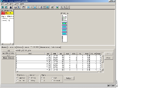
Step7 Click the Qos Thresholds subtab. The default selection is Near End, 15 Min, and MS ( Figure11-1).
Figure 11-1 Provisioning Thresholds for the STM-16 Card
Step8 As needed, complete the following:
a. Click MS , RS , Path, or Physical to provision the line, section, path, and physical options in Table 11-2 for each STM-N port.
b. Change the selection to Near End/Far End, 15 Min/1Day as necessary.
c. Click Refresh to view or modify the thresholds for each selection.
Table 11-2 STM-N Threshold Options (MS, RS, and Path)
|
Heading
|
Description
|
Options
|
|
Port
|
Port number
|
1 to16 for an STM-16 card, 1 to 4 for an STM-64 card
|
|
EB
|
Errored blocks
|
Numeric. Defaults (15 min/1 day):
MS
•21260/212600 (STM-16 Near and Far End)
•85040/850400 (STM-64 Near and Far End)
RS
•10000/100000 (Near End); 0/0 (Far End)
•10000/100000 (STM-64 Near End)
Path
•75/750 (STM-16/STM-64 Near and Far End)
|
|
ES
|
Errored seconds
|
Numeric. Default (15 min/1 day):
MS
•87/864 (STM-16/STM-64 Near and Far End)
RS
•500/5000 (Near End); 0/0 (Far End)
Path
•60/600 (STM-16/STM-64 Near and Far End)
|
|
SES
|
Severely errored seconds
|
Numeric. Defaults (15 min/1 day):
MS
•1/4 (Near and Far End)
RS
•500/5000 (Near End); 0/0 (Far End)
Path
•3/7 (STM-16/STM-64 Near and Far End)
|
|
BBE
|
Background block errors
|
Numeric. Defaults (15 min/1 day):
MS
•21260/212600 (STM-16 Near and Far End)
•85040/850400 (STM-64 Near and Far End)
RS
•10000/100000 (Near End);
•10000/100000 (STM-64 Near End)
Path
•25/250 (STM-16/STM-64 Near and Far End)
|
|
UAS
|
Unavailable seconds
|
Numeric. Defaults (15 min/1 day):
MS
•3/10 (STM-16/STM-64 Near and Far End)
Path
•10/10 (Near and Far End)
|
|
PSC
|
Protection Switching Count (MS)
|
Numeric. Defaults (15 min/1 day):
MS
•1/5 (Near End)
|
|
PSD
|
Protection Switch Duration (MS)
|
Numeric. Defaults (15 min/1 day):
MS
•300/600 (Near End)
|
|
PSC-W
|
Protection Switching Count (Working MS)
|
Numeric. Defaults (15 min/1 day):
MS
•1/5 (Near End)
|
|
PSD-W
|
Protection Switch Duration (Working MS)
|
Numeric. Defaults (15 min/1 day):
MS
•300/600 (Near End)
|
Step9 As needed, complete the following:
a. Click Physical to provision the physical options in Table 11-3 for each STM-N port.
b. Change the selection to 15 Min or 1 Day as necessary.
c. Click Refresh to view or modify the thresholds for each selection.
Table 11-3 STM-N Threshold Options (Physical)
|
Heading
|
Description
|
Options
|
|
Port
|
Port number
|
1 to 16 for an STM-16 card, 1 to 4 for an STM-64 card
|
|
LBC-HIGH
|
Laser bias current-maximum
|
Default (15 min/1 day): 200 percent
|
|
LBC-LOW
|
Laser bias current-minimum
|
Default (15 min/1 day): 20 percent
|
|
OPT-HIGH
|
Optical power transmitted-maximum
|
Default (15 min/1 day): 120 percent
|
|
OPT-LOW
|
Optical power transmitted-minimum
|
Default (15 min/1 day): 80 percent
|
|
OPR-HIGH
|
Optical power received-maximum
|
Default (15 min/1 day): 200 percent
|
|
OPR-LOW
|
Optical power received-minimum
|
Default (15 min/1 day): 50 percent
|
|
Set OPR
|
Setting the optical power received (OPR) establishes the received power level as 100percent. If the receiver power decreases, then the OPR percentage decreases to reflect the loss in receiver power. For example, if the receiver power decreases 3 dB, the OPR decreases 50 percent.
|
Step10 Click Apply .
Note See "Manage Alarms," for information about the Alarm Behavior tab, including alarm profiles and alarm suppression.
Stop. You have completed this procedure.