|
|

Table Of Contents
F40 Set the Optical Power Received Nominal Value
F41 Create a New User—Single Node
F42 Create a New User—Multiple Nodes
F45 Set Up or Change Open Shortest Path First Protocol
F46 Provision the IIOP Listener Port on the ONS 15600 SDH
F47 Provision the IIOP Listener Port on the CTC Computer
F48 Set Up External or Line Timing
F50 Provision External Alarms and Virtual Wires
F51 Provision External Controls for External Alarms and Virtual Wires
Turn Up Node
This chapter explains how to provision a single CiscoONS15600SDH node and turn it up for service, including node name, date and time, SDH timing references, network attributes such as IP address and default router, users and user security, and card protection groups.
Before You Begin
Complete the procedures applicable to your site plan from the following chapters:
•
"Install the Bay and Backplane Connections"
•
•
This section lists the chapter procedures (NTPs). Turn to a procedure for a list of its tasks (DLPs).
1.
2.
3.
4.
5.
6.
7.
8.
9.
10.
11.
NTP-F22 Verify Card Installation
Purpose
This procedure verifies that the ONS15600SDH node is ready for turn up.
Tools/Equipment
None
Prerequisite Procedures
"Install the Bay and Backplane Connections"
Required/As Needed
Required
Onsite/Remote
Onsite
Security Level
Retrieve or higher
Step1
Step2
Note
Step3
Step4
Note
Step5
Step6
Step7
Step8
a.
b.
c.
•
•
Note
Step9
Step10
Note
Stop. You have completed this procedure.
DLP-F40 Set the Optical Power Received Nominal Value
Step1
Step2
Step3
Step4
Step5
Step6
Step7
NTP-F23 Create Users and Assign Security
Step1
Note
Step2
Note
Stop. You have completed this procedure.
DLP-F41 Create a New User—Single Node
Purpose
This task creates a new user for one ONS15600SDH.
Tools/Equipment
None
Prerequisite Procedures
Required/As Needed
As needed
Onsite/Remote
Onsite or remote
Security Level
Superuser only
Step1
Step2
Step3
•
•
•
•
Note
Step4
Step5
DLP-F42 Create a New User—Multiple Nodes
Purpose
This task adds a new user to multiple ONS15600SDH nodes.
Tools/Equipment
None
Prerequisite Procedures
Required/As Needed
As needed
Onsite/Remote
Onsite or remote
Security Level
Superuser only
Note
Step1
Step2
Step3
Step4
•
•
•
•
Note
Step5
Step6
Step7
Step8
NTP-F24 Set Up Date, Time, and Contact Information
Step1
Step2
Step3
•
•
•
•
•
Tip
CTC uses the latitude and longitude to position ONS 15600 SDH icons on the network view map. To convert a coordinate in degrees to degrees and minutes, multiply the number after the decimal by 60. For example, the latitude 38.250739 converts to 38 degrees, 15 minutes (.250739 x 60 = 15.0443, rounded to the nearest whole number).
•
•
If you do not use an SNTP or NTP server, complete the Date and Time fields. The ONS 15600 SDH will use these fields for alarm dates and times. (CTC displays all alarms in the login node's time zone for cross network consistency.)
Note
If you check the Use NTP/SNTP Server box, type the IP address of an NTP/SNTP server or the IP address of another ONS 15600 SDH with NTP/SNTP Server enabled.
If you check Enable Firewall for the ONS 15600 SDH proxy server (see the "DLP-F43 Provision IP Settings" task ), external ONS 15600 SDH network elements (NEs) must reference the gateway ONS 15600 SDH NE for NTP/SNTP timing. For more information about the ONS 15600 SDH gateway settings, refer to the Cisco ONS 15600 SDH Reference Manual.
Caution
•
•
•
Step4
Step5
Step6
Stop. You have completed this procedure.
NTP-F25 Set Up CTC Network Access
Step1
Step2
Step3
Step4
Stop. You have completed this procedure.
DLP-F43 Provision IP Settings
Caution
Step1
Step2
Step3
•
•
Note
•
Note
•
•
•
•
–
–
Step4
Step5
Both ONS 15600 SDH TSC cards will reboot, one at a time. Next, a "Lost node connection, switching to network view" message appears. The reset causes the standby TSC to become the active TSC.
Step6
Step7
Step8
Step9
DLP-F44 Create a Static Route
Step1
Step2
Step3
•
•
•
•
Step4
Note
Step5
DLP-F45 Set Up or Change Open Shortest Path First Protocol
Note
Note
Note
Step1
Step2
•
•
Step3
•
•
Step4
a.
b.
•
•
•
c.
The authentication button label changes to Simple Password.
Step5
•
•
•
•
•
•
Step6
Note
a.
b.
•
•
•
•
c.
Step7
a.
b.
•
•
•
•
•
•
c.
Step8
If you changed the Area ID, the TSC cards will reset, one at a time. The reset will take approximately 10 to 15 minutes.
Step9
NTP-F98 Set Up the ONS 15600 SDH for Firewall Access
Step1
Step2
Step3
Stop . You have completed this procedure .
DLP-F46 Provision the IIOP Listener Port on the ONS 15600 SDH
Step1
Step2
•
•
•
Table 4-1 Ports Used by the TSC Cards
0
Never used
21
FTP control
23
Telnet
80
HTTP
111
rpc (not used; but port is in use)
513
rlogin (not used; but port is in use)
<1023
Default CTC listener ports
1080
Proxy server
2001-2017
I/O1 card Telnet
2018
DCC processor on active TSC
2361
TL1
3082
TL1
3083
TL1
5001
MS-SPRing2 server port
5002
MS-SPRing client port
7200, 7209, 7210
SNMP3 input port
9100
EQM port
9101
EQM port 2
9401
TSC boot port
9999
Flash manager
57790
Default TSC listener port
1 I/O = input/output
2 MS-SPRing = multiplex section-shared protection ring
3 SNMP = simple network management protocol
Step3
Step4
Both TSCs will reboot, one at a time. The reboot takes approximately 15 minutes.
Step5
DLP-F47 Provision the IIOP Listener Port on the CTC Computer
Step1
Step2
Step3
•
•
•
Step4
Step5
Step6
Step7
Step8
NTP-F26 Set Up Timing
Purpose
This procedure provisions the ONS15600SDH timing.
Tools/Equipment
None
Prerequisite Procedures
Required/As Needed
Required
Onsite/Remote
Onsite or remote
Security Level
Provisioning or higher
Step1
Step2
Step3
Note
Stop. You have completed this procedure.
DLP-F48 Set Up External or Line Timing
Note
Step1
Step2
•
•
•
•
•
•
Step3
Note
•
•
•
•
•
•
•
Step4
•
•
Step5
Note
Step6
DLP-F49 Set Up Internal Timing
Caution
Step1
Step2
•
•
•
•
•
Step3
Step4
•
•
•
Step5
Step6
Step7
Step8
Step9
•
•
•
Step10
Step11
Step12
NTP-F27 Create a 1+1 (LMSP) Protection Group
Step1
Step2
Step3
Step4
Step5
•
•
•
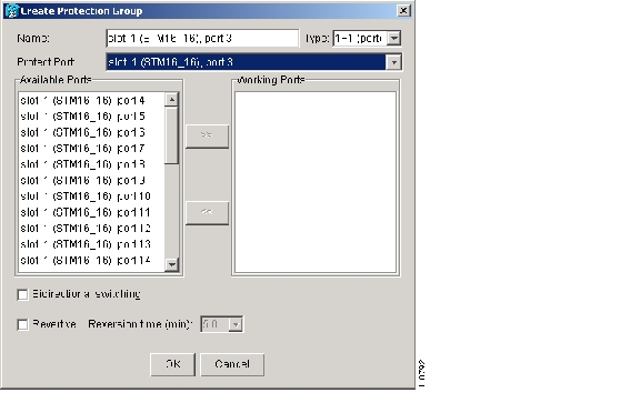
After you choose the protect port, a list of working ports available for protection appears in the Available Ports list. If no cards are available, no ports appear. If this occurs, you cannot complete this task until you install the physical cards or pre provision the ONS 15600 SDH slots using the "NTP-F14 Preprovision a Slot" procedure .
Figure 4-1 Creating a 1+1 Protection Group
Step6
Step7
•
If the Bidirectional switching check box is not selected, the near-end and far-end nodes switch independently of each other. For example, if the near-end node has an LOS on its working port it switches to the protection port. If the far-end node does not have a LOS, traffic remains on the working port.
•
•
Step8
Stop. You have completed this procedure.
NTP-F28 Set Up SNMP
Step1
Step2
Step3
Step4
•
•
Note
•
•
•
Note
Step5
Step6
Stop. You have completed this procedure.
NTP-F29 Set the User Code for Card Inventory
Step1
Step2
Step3
Step4
Stop. You have completed this procedure.
NTP-F30 Configure a Node Using an Existing Database
Note
Step1
Step2
Step3
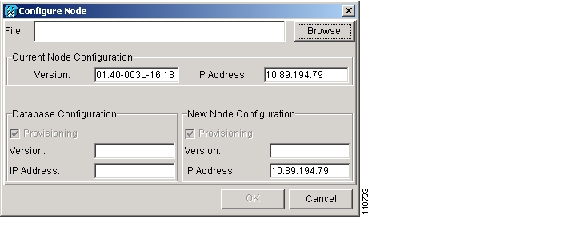
Step4
Figure 4-2 Configuring a Node with Another Node's Database Backup
Step5
Step6
•
•
•
Step7
•
•
•
Step8
Step9
Stop. You have completed this procedure.
NTP-F31 Set External Alarms and Controls
Step1
Step2
Step3
Stop. You have completed this procedure.
DLP-F50 Provision External Alarms and Virtual Wires
Step1
Step2
•
•
•
Note
•
•
•
Step3
Step4
Step5
DLP-F51 Provision External Controls for External Alarms and Virtual Wires
Step1
Step2
•
•
•
•
Step3
Step4
Step5
![]()
![]()
![]()
![]()
![]()
![]()
![]()
![]()
Posted: Thu Feb 26 17:29:45 PST 2004
All contents are Copyright © 1992--2004 Cisco Systems, Inc. All rights reserved.
Important Notices and Privacy Statement.