|
|

Table Of Contents
F92 Filter the Display of Circuits
F95 Change Active and Standby Span Color
F96 Edit SNCP Circuit Path Selectors
F98 Roll the Source or Destination of One Optical Circuit
F99 Roll One Cross-Connection from an Optical Circuit to a Second Optical Circuit
F100 Roll Two Cross-Connections on One Optical Circuit Using Automatic Routing
F101 Roll Two Cross-Connections on One Optical Circuit Using Manual Routing
F102 Roll Two Cross-Connections from One Optical Circuit To a Second Optical Circuit
Manage Circuits
This chapter explains how to manage CiscoONS15600SDH optical circuits.
Note
The ONS15600SDH Software Release 1.4 does not support a full state model. As a result, the circuit state cannot be changed; it is always In Service (IS).
Before You Begin
To create circuits, complete the procedures as needed in "Create Circuits"
To clear any alarm or trouble conditions, refer to the CiscoONS15600SDH Troubleshooting Guide.
This section lists the chapter procedures (NTPs). Turn to a procedure for applicable tasks (DLPs).
1.
2.
3.
4.
5.
6.
Note
NTP-F60 Locate and View Circuits
Purpose
This procedure locates and displays ONS15600 circuits.
Tools/Equipment
None
Prerequisite Procedures
F42 Create an Automatically Routed Optical Circuit or
Required/As Needed
As needed
Onsite/Remote
Onsite or remote
Security Level
Retrieve or higher
Step1
Step2
Step3
Step4
Step5
Stop. You have completed this procedure.
DLP-F90 View Circuit Information
Purpose
This task displays ONS15600SDH circuits.
Tools/Equipment
None
Prerequisite Procedures
Required/As Needed
As needed
Onsite/Remote
Onsite or remote
Security Level
Retrieve or higher
Step1
•
•
•
Note
Step2
•
•
•
•
•
•
•
•
•
•
•
Step3
DLP-F91 Search for Circuits
Step1
•
•
•
Step2
Step3
Step4
Step5
•
•
•
•
Step6
Step7
Step8
DLP-F92 Filter the Display of Circuits
Step1
•
•
•
Step2
Step3
Step4
•
•
•
•
•
•
•
•
•
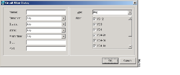
Figure 9-1 Entering Circuit Filter Criteria
Step5
Step6
Step7
DLP-F93 View Circuits on a Span
Step1
Step2
In the Circuits on Span dialog box, you can view the following information for all circuits provisioned on the span:
•
•
•
•
•
Note
Step3
NTP-F61 Modify and Delete Circuit Characteristics
Purpose
Use this procedure to edit or change the properties of ONS15600SDH circuits.
Tools/Equipment
None
Prerequisite Procedures
F42 Create an Automatically Routed Optical Circuit or
F43 Create a Manually Routed Optical Circuit or
F44 Create a Unidirectional Optical Circuit with Multiple Drops
Required/As Needed
As needed
Onsite/Remote
Onsite or remote
Security Level
Provisioning or higher
Step1
Step2
Step3
Step4
Step5
Stop. You have completed this procedure.
DLP-F94 Edit a Circuit Name
Purpose
This task edits a circuit name.
Tools/Equipment
None
Prerequisite Procedures
Required/As Needed
As needed
Onsite/Remote
Onsite or remote
Security Level
Provisioning or higher
Step1
Step2
Step3
Step4
Step5
Step6
Step7
DLP-F95 Change Active and Standby Span Color
Step1
Step2
Step3
•
•
•
Step4
a.
b.
c.
d.
Step5
a.
b.
c.
d.
Step6
a.
b.
c.
d.
Step7
DLP-F96 Edit SNCP Circuit Path Selectors
Step1
Step2
Step3
Note
Step4
•
•
•
•
•
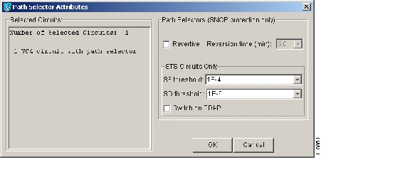
Figure 9-2 Editing SNCP Path Selectors
Step5
Step6
DLP-E97 Delete Circuits
Purpose
This task deletes circuits.
Tools/Equipment
None
Prerequisite Procedures
Required/As Needed
As needed
Onsite/Remote
Onsite or remote
Security Level
Provisioning or higher
Step1
Step2
Step3
Step4
Step5
Step6
Note
Step7
Step8
Note
Step9
NTP-F62 Monitor a J1 Path Trace
Purpose
This procedure allows you to monitor interruptions or changes to circuit traffic and edit the expected path trace string.
Tools/Equipment
ONS15600SDH cards capable of transmitting and/or receiving path trace must be installed.
Prerequisite Procedures
F42 Create an Automatically Routed Optical Circuit or
F43 Create a Manually Routed Optical Circuit or
F44 Create a Unidirectional Optical Circuit with Multiple Drops
Required/As Needed
As needed
Onsite/Remote
Onsite or remote
Security Level
Provisioning or higher
Step1
Step2
Step3
Step4
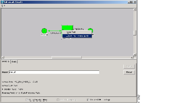
Figure 9-3 Selecting the Edit Path Trace Option (Manual)
Step5
Step6
Manual sets the string entered in the Current Expected String field is the baseline. An alarm is raised when a string that differs from the Current Expected String is received.
Step7
Step8
Step9
Step10
•
•
•
The Expect and Receive strings are updated every few seconds. When you open the detailed circuit window, path trace is indicated by an M (manual path trace) at the circuit source and destination ports.
Caution
Step11
Stop. You have completed this procedure.
NTP-F63 Bridge and Roll Traffic
Purpose
This procedure reroutes live traffic without interrupting service. You can use the Bridge and Roll wizard for maintenance functions such as card replacement or load balancing. A circuit consists of a source facility, destination facility(s), and intermediate facilities (path).
Tools/Equipment
None
Prerequisite Procedures
•
•
•
•
Required/As Needed
As needed
Onsite/Remote
Onsite or remote
Security Level
Provisioning and higher
Note
Step1
Step2
Step3
Step4
Step5
Step6
Stop. You have completed this procedure.
DLP-F98 Roll the Source or Destination of One Optical Circuit
Step1
Step2
Step3
Step4
Step5
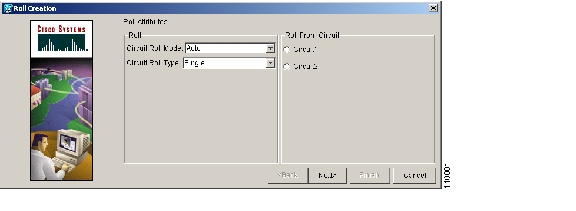
•
•
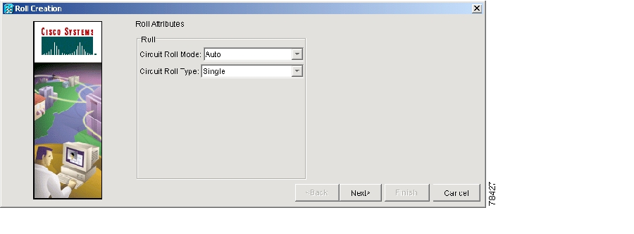
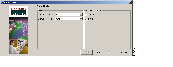
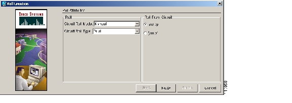
Figure 9-4 Selecting Single Roll Attributes
Step6
Step7
This facility is the fixed location in the cross-connection involved in the roll process. The identifier appears in the text box below the graphic image. The facility that is not selected is the Roll From path. The Roll From path is deleted after the roll is completed.
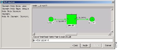
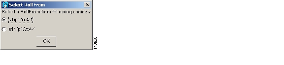
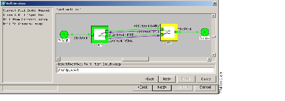
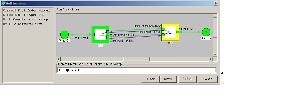
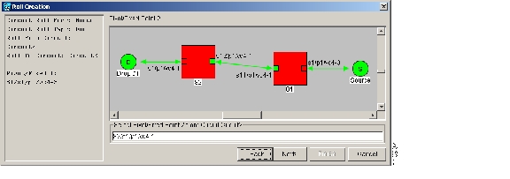
Figure 9-5 Selecting a Path
Step8
Step9
This selection indicates the Roll To facility.
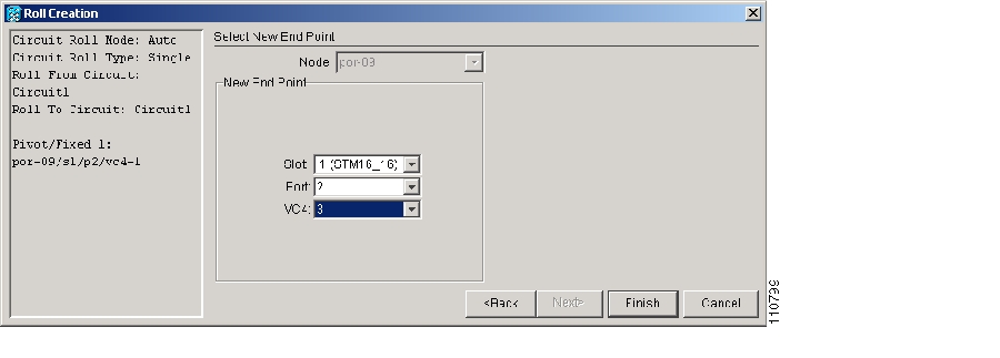
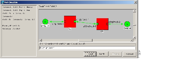
Figure 9-6 Selecting a New Endpoint
Step10
Step11
•
•
•
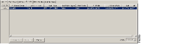
Note
Figure 9-7 Viewing the Rolls Tab
Step12
Step13
Step14
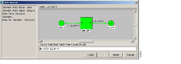
DLP-F99 Roll One Cross-Connection from an Optical Circuit to a Second Optical Circuit
Purpose
This task reroutes a cross-connection on one circuit onto another circuit, resulting in a new destination.
Tools/Equipment
None
Prerequisite Procedures
F53 Provision SDH DCC Terminations for the ports involved in the roll
Required/As Needed
As needed
Onsite/Remote
Onsite or remote
Security Level
Provisioning or higher
Step1
Step2
Step3
The circuits must be in the Active state; in addition, they must be the same size and direction for you to complete a roll.
Note
Note
Step4
Step5
•
•
•
Figure 9-8 Selecting Roll Attributes for a Single Roll onto a Second Circuit
Step6
Step7
This facility is the fixed location in the cross-connection involved in the roll process. The identifier appears in the text box below the graphic image. The facility that is not selected is the Roll From path. The Roll From path is deleted after the roll is completed.
Figure 9-9 Selecting the Fixed Path
Step8
Step9
Step10
The states of the Roll From and Roll To circuits change from Active to Roll Pending in the Circuits tab.
Step11
•
•
•
Note
Step12
Step13
The roll is cleared from the Rolls tab and the new rolled circuit on Circuits tab returns to the Active state.
Step14
DLP-F100 Roll Two Cross-Connections on One Optical Circuit Using Automatic Routing
Note
Step1
Step2
Step3
Step4
Step5
a.
Note
b.
Figure 9-10 Selecting Dual Roll Attributes
Step6
Step7
This path is a fixed point in the cross connection involved in the roll process. The path identifier appears in the text box below the graphic image. The path that is not selected contains the Roll From path. The Roll From path is deleted after the roll is completed.
Figure 9-11 Selecting the First Fixed Path on a Circuit
Step8
Step9
•
•
Figure 9-12 Selecting the Roll From Path
Step10
The path that is not selected is the Roll From path. The Roll From path is deleted after the roll is completed. The path identifier appears in the text box below the graphic image.
Figure 9-13 Selecting the Second Fixed Path on a Circuit
Step11
Step12
•
•
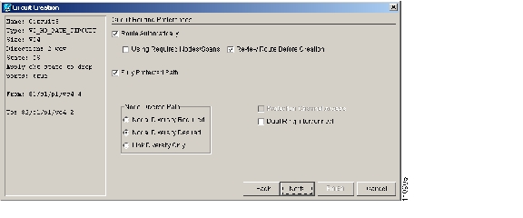
Figure 9-14 Setting Circuit Routing Preferences
Step13
•
•
•
Step14
•
•
•
•
Step15
a.
b.
c.
d.
Step16
a.
b.
Step17
In the Circuits tab, verify that a new circuit appears. This circuit is the Roll To circuit. It is designated with the Roll From circuit name appended with ROLL**.
Step18
•
•
•
Note
Note
Step19
Note
Step20
Note
Step21
DLP-F101 Roll Two Cross-Connections on One Optical Circuit Using Manual Routing
Note
Step1
Step2
Step3
Step4
Step5
a.
b.
Figure 9-15 Selecting Dual Roll Attributes
Step6
Step7
This path is a fixed point in the cross-connection involved in the roll process. The path identifier appears in the text box below the graphic image. The path that is not selected contains the Roll From path. The Roll From path is deleted after the roll is completed.
Figure 9-16 Selecting the First Fixed Path on a Circuit
Step8
Step9
•
•
Figure 9-17 Selecting the Roll From Point
Step10
The path that is not selected is the Roll From path. The Roll From path is deleted after the roll is complete. The path identifier appears in the text box below the graphic image.
Figure 9-18 Selecting the Second Fixed Path on the Circuit
Step11
Step12
Step13
•
•
Step14
•
•
•
Step15
The green arrows pointing from the source node to other network nodes indicate spans that are available for routing the circuit.
Step16
Step17
This circuit is the Roll To circuit. It is designated with the Roll From circuit name appended with ROLL**.
Step18
•
•
•
Note
Step19
Note
Step20
Note
Step21
DLP-F102 Roll Two Cross-Connections from One Optical Circuit To a Second Optical Circuit
Step1
Step2
Step3
The Roll From path will be on one circuit and the Roll To path will be on the other circuit. The circuits must be in the Active state; in addition, they must be the same size and direction for you to complete a roll.
Note
Note
Step4
Step5
•
•
•
Figure 9-19 Selecting Roll Attributes for a Dual Roll onto a Second Circuit
Step6
Step7
This path is a fixed point in the cross-connection involved in the roll process. The path identifier appears in the text box below the graphic image. The path that is not selected contains the Roll From path. The Roll From path is deleted after the roll is completed.
Figure 9-20 Selecting the First Fixed Path on a Circuit
Step8
Step9
•
•
The circuit state for the Roll To path changes from Active to Roll Pending.
Figure 9-21 Selecting the Roll From Connection
Step10
The path that is not selected is the Roll From path. The Roll From path is deleted after the roll is completed. The path identifier appears in the text box below the graphic image.
Figure 9-22 Selecting the Second Fixed Path on the Circuit
Step11
Step12
Step13
•
•
•
Note
Step14
Note
Step15
Note
Step16
DLP-F103 Delete a Roll
Purpose
This task deletes a roll.
Tools/Equipment
None
Prerequisite Procedures
Required/As Needed
As needed
Onsite/Remote
Onsite or remote
Security Level
Provisioning or higher
Note
Step1
Step2
Step3
Step4
Step5
Step6
NTP-F64 Convert Circuits to TL1 Cross-Connections
Note
Step1
Step2
Step3
The circuit(s) must have an INCOMPLETE or ACTIVE status.
Step4
Step5
The Convert to TL1 Cross Connect Results dialog box displays the results of the conversion. If any circuits could not be converted, those circuits are listed.
Step6
If the circuit you selected had an INCOMPLETE status, its status will not change. If you selected an ACTIVE (complete) circuit, its status will change to UPGRADABLE.
Step7
After you repair or replace all missing cross-connects, CTC automatically merges them and the circuit status changes to UPGRADABLE.
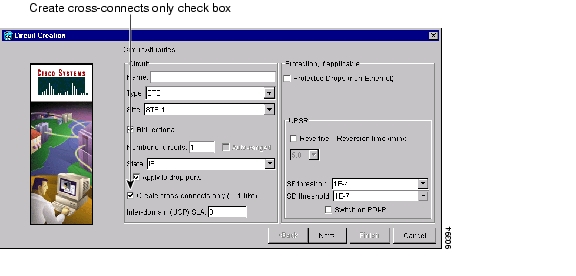
Figure 9-23 Choosing the Cross-Connects Only Option
Step8
Stop. You have completed this procedure.
NTP-F65 Upgrade TL1 Cross-Connects to CTC Circuits
Step1
Step2
Step3
Step4
Step5
The circuit status changes to ACTIVE.
Step6
Stop. You have completed this procedure.
![]()
![]()
![]()
![]()
![]()
![]()
![]()
![]()
Posted: Thu Feb 26 17:33:43 PST 2004
All contents are Copyright © 1992--2004 Cisco Systems, Inc. All rights reserved.
Important Notices and Privacy Statement.