cc/td/doc/product/ong/600_sdh/sdh60014
hometocprevnextglossaryfeedbacksearchhelp
PDF

Table Of Contents

Install Cards and Fiber-Optic Cable

Before You Begin

F22 Delete a Card from CTC

F24 Install Fiber-Optic Cables in a 1+1 Configuration

F25 Install Fiber-Optic Cables for SNCP Configurations

F26 Install Fiber-Optic Cables for MS-SPRing Configurations

F27 Route Fiber-Optic Cables

Install Cards and Fiber-Optic Cable


This chapter explains how to install the CiscoONS15600SDH cards and fiber-optic cable (fiber).

Before You Begin

Before beginning this chapter, complete "Install the Bay and Backplane Connections"

This section lists the chapter procedures (NTPs). Turn to a procedure for applicable tasks (DLPs).

1. F10 Install the Common Control Cards—Complete this procedure before continuing with the "NTP-F11 Install the STM-N Cards" procedure.

2. F11 Install the STM-N Cards—Complete this procedure before continuing with the "NTP-F16 Install the Fiber-Optic Cables" procedure.

3. F13 Install the Filler Cards—Complete as needed to fill any unused optical card slots with filler cards.

4. F14 Preprovision a Slot—Complete as needed to provision an empty card slot.

5. F15 Remove and Replace a Card—Complete as needed.

6. F16 Install the Fiber-Optic Cables—Complete this procedure to install and route the fiber-optic cables.

7. F17 Replace the Front Door—Complete as needed.


Warning Only trained and qualified personnel should be allowed to install, replace, or service this equipment.


Warning Blank faceplates (filler panels) serve three important functions: they prevent exposure to hazardous voltages and currents inside the chassis; they contain electromagnetic interference (EMI) that might disrupt other equipment; and they direct the flow of cooling air through the chassis. Do not operate the system unless all cards, power modules, and faceplates are in place.


NTP-F10 Install the Common Control Cards

Purpose

This procedure installs the Timing and Shelf Control (TSC) cards and then the Core Cross Connect (CXC) cards, which are required to operate the ONS15600SDH.

Tools/Equipment

Redundant TSC cards and CXC cards

Prerequisite Procedures

F8 Perform the Bay Installation Acceptance Test

Required/As Needed

Required

Onsite/Remote

Onsite

Security Level

None


Warning During this procedure, wear grounding wrist straps to avoid ESD damage to the card. Do not directly touch the backplane with your hand or any metal tool, or you could shock yourself.


Caution Always use the supplied ESD wristband when working with a powered ONS15600SDH. Plug the wristband cable into the ESD jack located on the lower-left outside edge of the shelf.


Note For information about the TSC and CXC cards (such as LED information), refer to the CiscoONS15600SDH Reference Manual.


Step1 Remove the card from the box and antistatic sleeve.

Step2 Install cards in the following sequence:

a. Slot 5, TSC card

b. Slot 10, TSC card

c. Slot 6, CXC card

d. Slot 8, CXC card

Step3 Open the card ejectors.

Step4 Slide the card along the top and bottom guide rails into the correct slot. The CXC faceplate occupies two slots. Insert the card until it contacts the backplane.


Note CXC cards will not appear in Cisco Transport Controller (CTC) until at least one TSC card is installed.


Step5 Close the ejectors.

Step6 Verify the LED activity as described in Table2-1.

Table 2-1 LED Activity During TSC and CXC Card Installation

Card Type
LED Activity

TSC

1. All LEDs turn on for 20 to 60 seconds.

2. The STAT LED blinks and all other LEDs turn off for 30 to 50 seconds.

3. All LEDs blink once and then turn off for 10 seconds.

4. The SRV LED goes green and the applicable timing indicator goes green (line, external, freerun, holdover).

CXC

1. The STAT and SRV LEDs turn on for 20 seconds.

2. The STAT LED blinks and the SRV LED turns off for 30 seconds.

3. All LEDs blink once and the SRV LED comes on.


Step7 On the TSC card, verify that the ACT/STBY LED is on if the card is active (green) and off if the card is standby. If it is not, refer to the CiscoONS15600SDH Troubleshooting Guide.

Step8 Repeat Steps 1 through 7 for each TSC and CXC card you need to install.


Caution Do not operate the ONS15600SDH with a single TSC card or a single CXC card installed. Always operate the shelf with two TSC cards and two CXC cards.


Step9 After you have logged into CTC, verify that the card appears in the correct slot on the CTC node view. See "Connect the Computer and Log into the GUI" for CTC information and setup instructions.


Tip When an active TSC card has a newer version of the ONS15600SDH software installed than the newly installed TSC, the active TSC card automatically copies the software version on the new TSC. You do not need to do anything in this situation. The loading TSC card boots up in the normal manner. After loading the new software for several minutes, the newly installed TSC card becomes the standby card.


Stop. You have completed this procedure.


NTP-F11 Install the STM-N Cards

Purpose

This procedure explains how to install the optical (STM-N) cards (STM-16 and STM-64).

Tools/Equipment

STM-16 and STM-64 cards (as applicable)

Prerequisite Procedures

F8 Perform the Bay Installation Acceptance Test

F10 Install the Common Control Cards

Required/As Needed

At least one optical card is required to carry traffic. Install according to site plan, if available.

Onsite/Remote

Onsite

Security Level

None


Warning During this procedure, wear grounding wrist straps to avoid ESD damage to the card. Do not directly touch the backplane with your hand or any metal tool, or you could shock yourself.


Caution Always use the supplied ESD wristband when working with a powered ONS15600SDH. Plug the wristband cable into the ESD jack located on the lower-left outside edge of the shelf.


Warning Class 1 laser product.


Warning Invisible laser radiation may be emitted from the end of the unterminated fiber cable or connector. Do not stare into the beam or view directly with optical instruments. Viewing the laser output with certain optical instruments (for example, eye loupes, magnifiers, and microscopes) within a distance of 100 mm may pose an eye hazard. Use of controls or adjustments or performance of procedures other than those specified may result in hazardous radiation exposure.


Note For information about the optical cards, refer to the CiscoONS15600SDH Reference Manual.


Step1 Remove the card from the box and antistatic sleeve.


Caution Setting an STM-N card on its connectors can cause damage to the connectors.


Step2 Open the card ejectors.

Step3 Slide the card along the top and bottom guide rails into the correct slot: Slots 1 to 4 and 11 to 14 are available for optical cards. Insert the card until it contacts the backplane.

Step4 Close the ejectors.

Step5 Verify the LED activity on the card faceplate:

1. The STAT, SRV, SD, SF, and LASER ON LEDs turn on for 20 seconds.

2. The STAT LED blinks and all other LEDs turn on for 30 to 50 seconds.

3. All LEDs blink once and the SRV and LASER ON LEDs illuminate.


Note If the LEDs do not turn on, check that the power breakers on the power distribution unit (PDU) are on. Refer to the CiscoONS15600SDH Troubleshooting Guide.


Note If you install an optical card in a slot provisioned for another optical rate, the same LED sequence occurs but the SRV LED does not turn on and only the LASER ON LED turns on. You will see a mismatched equipment (MEA) alarm for that slot when you open CTC.


Step6 After you have logged into CTC, verify that the card appears in the correct slot on the CTC node view. See "Connect the Computer and Log into the GUI" for CTC information and setup instructions.

Step7 Complete the "NTP-F16 Install the Fiber-Optic Cables" task.

Stop. You have completed this procedure.


NTP-F13 Install the Filler Cards

Purpose

This procedure explains how to install the filler cards (blank faceplates) in any unused optical card slots.

Tools/Equipment

Filler card(s) (Cisco P/N 15600-IO-FILLER)

Prerequisite Procedures

F10 Install the Common Control Cards

F11 Install the STM-N Cards

Required/As Needed

As needed for any unused card slots

Onsite/Remote

Onsite

Security Level

None


Warning Blank faceplates (filler panels) serve three important functions: they prevent exposure to hazardous voltages and currents inside the chassis; they contain electromagnetic interference (EMI) that might disrupt other equipment; and they direct the flow of cooling air through the chassis. Do not operate the system unless all cards, power modules, and faceplates are in place.


Step1 Open the card ejectors.

Step2 Slide the card along the top and bottom guide rails into the correct optical card slot.

Step3 Close the ejectors.

Step4 Repeat for any remaining unused card slots.


Note CTC automatically detects filler cards and includes them in the graphical shelf display.


Stop. You have completed this procedure.


NTP-F14 Preprovision a Slot

Purpose

This procedure explains how to preprovision a slot before card installation.

Tools/Equipment

None

Prerequisite Procedures

F18 Set Up Computer for CTC

F19 Set Up CTC Computer for Local Craft Connection to the ONS15600SDH or

F20 Set Up a CTC Computer for a Corporate LAN Connection to the ONS15600SDH

Required/As Needed

As needed

Onsite/Remote

Onsite or remote

Security Level

Provisioning or higher


Step1 Complete the "DLP-F36 Log into CTC" task at the node where you want to preprovision the slot.

Step2 Right-click the empty slot where you will later install a card.

Step3 From the Add Card drop-down menu, choose the card type that will be installed. The valid preprovision types for slots 1-4 and 11-14 STM16_16 and STM64_4. The valid preprovision type for slots 5, 10 is TSC and for slots 6, 8 is CXC.


Note An Improper Removal Alarm (IMPROPRMVL) occurs in CTC after the card is preprovisioned.


Note A preprovisioned slot appears yellow in CTC rather than white for an installed card.


Stop. You have completed this procedure.


NTP-F15 Remove and Replace a Card

Purpose

This procedure explains how to remove a card from an ONS15600SDH shelf.

Tools/Equipment

None

Prerequisite Procedures

F10 Install the Common Control Cards or

F11 Install the STM-N Cards

Required/As Needed

As needed

Onsite/Remote

Onsite

Security Level

Provisioning or higher


Step1 If you are not logged into CTC and you need to remove a card, remove the card as described in Step4. When you log into CTC, troubleshoot the Improper Removal Alarm (IMPROPRMVL) with the CiscoONS15600SDH Troubleshooting Guide. .

Step2 If you are logged into CTC, complete the "DLP-F22 Delete a Card from CTC" task.

Step3 If you are removing an optical card with cables connected to the front:

a. Rotate the plastic cable latch over the cable routing channel that corresponds to the optical card so that the latch is open (not blocking the routing channel).

b. Squeeze the latches on both sides of the connector and pull the connector out of the adapter on the front of the card.

Step4 Physically remove the card:

a. Open the card latches/ejectors.

b. Use the latches/ejectors to gently pull the card forward and away from the shelf.


Caution Do not allow the connectors on the card to touch anything as you remove the card.


Step5 Insert the new card using one of the following procedures as applicable:

F10 Install the Common Control Cards

F11 Install the STM-N Cards

Stop. You have completed this procedure.


DLP-F22 Delete a Card from CTC

Purpose

This task deletes a card from CTC.

Tools/Equipment

None

Prerequisite Procedures

F36 Log into CTC

Required/As Needed

As needed

Onsite/Remote

Onsite or remote

Security Level

Provisioning or higher


Step1 In node view, right-click the card you want to delete on the shelf graphic. A drop-down menu appears.

Step2 Choose Delete Card from the menu and click Yes in the confirmation dialog box.

You cannot delete a card if any of the following conditions apply:

The card is part of a protection group; see the "DLP-F117 Delete a 1+1 Protection Group" task .

The card has any circuits; see the "DLP-E97 Delete Circuits" task .

The card is being used for timing; see the "DLP-F118 Change the Node Timing Source" task .

The card has a SDH data communications channel (DCC) termination; see the "NTP-F70 Delete an RS-DCC Termination" procedure .


Note If the card that you deleted is still installed, it will reboot and reappear in CTC.


Step3 Return to your originating procedure (NTP).


NTP-F16 Install the Fiber-Optic Cables

Purpose

This procedure explains how to install fiber-optic cables on the optical cards.

Tools/Equipment

Optical Gateway Interface(OGI) fiber-optic cables:

STM-16: 72-3699-01-XXX (where XXX is the cable length in meters; for instance, 002 is 2 meters)

STM-64: 72-3708-01-XXX (where XXX is the cable length in meters)

Attenuators suitable for STM-16 and STM-64 attenuation (3 dB for short haul and 15 to 20 dB for long haul)

Optical power meter

Prerequisite Procedures

F11 Install the STM-N Cards

Required/As Needed

Required

Onsite/Remote

Onsite

Security Level

None


Warning Class 1 laser product.


Warning Invisible laser radiation may be emitted from the end of the unterminated fiber cable or connector. Do not stare into the beam or view directly with optical instruments. Viewing the laser output with certain optical instruments (for example, eye loupes, magnifiers, and microscopes) within a distance of 100 mm may pose an eye hazard. Use of controls or adjustments or performance of procedures other than those specified may result in hazardous radiation exposure.


Warning Because invisible laser radiation may be emitted from the aperture of the port when no cable is connected, avoid exposure to laser radiation and do not stare into open apertures.


Caution Always use the supplied ESD wristband when working with a powered ONS15600SDH. Plug the wristband cable into the ESD jack located on the left-hand outside edge of the shelf.


Note The STM-16 cable can terminate both STM-16 and STM-64 signals but when used with STM-64 cards the cable has six unused optical connections. STM-64 cables are recommended for termination of STM-64 signals. When STM-16 cable is being used for STM-64 only connectors 3 and 4 are used.


Step1 Test the optical receive levels for the cards installed and attenuate accordingly. See Table2-2 for the minimum and maximum levels.

Table 2-2 Optical Transmit and Receive Levels 

Card
Transmit
Receive
Minimum
Maximum
Minimum
Maximum

STM16 LR16 1550

-2 dBm

+3 dBm

-28 dBm

-9 dBm

STM64 LR4 1550

+4 dBm

+7 dBm

-22 dBm

-9 dBm

STM16 SR16 1310

-10 dBm

-3 dBm

-18 dBm

-3 dBm

STM64 SR4 1310

-6 dBm

-1 dBm

-11 dBm

-1 dBm


Caution Never create physical (hard) fiber loopbacks on the STM-N LH ports unless you use the proper attenuator. Using fiber loopbacks without the proper attenuator causes damage to STM-N LH cards' receivers.


Step2 As necessary, complete the "DLP-F24 Install Fiber-Optic Cables in a 1+1 Configuration" task.

Step3 As necessary, complete the "DLP-F25 Install Fiber-Optic Cables for SNCP Configurations" task.

Step4 As necessary, complete the "DLP-F26 Install Fiber-Optic Cables for MS-SPRing Configurations" task.

Step5 Complete the "DLP-F27 Route Fiber-Optic Cables" task.

Stop. You have completed this procedure.


DLP-F24 Install Fiber-Optic Cables in a 1+1 Configuration

Purpose

This task installs fiber-optic cables on optical (STM-N) cards in a 1+1 linear configuration.

Tools/Equipment

Fiber-optic cables

Prerequisite Procedures

F11 Install the STM-N Cards

NTP-F94 Clean Fiber Connectors and Adapters, page 14-18

Required/As Needed

As needed

Onsite/Remote

Onsite

Security Level

None


Note With all fiber types, network planners/engineers should review the relative fiber type and optics specifications to determine attenuation, dispersion, and other characteristics to ensure appropriate deployment.


Step1 Align the white stripe of the cable connector with the white stripe on the receiving OGI connector of the faceplate connection point. Each card has four connectors on the faceplate.

Table 2-3  shows the OGI connector pinouts on the STM-16 card faceplate.

Table 2-3 OC48/STM16 Cards OGI Connector Pinout

Connector
OGI Pin and Card Port

1

1

2

3

4

5

6

7

8

Receive 4

Transmit 4

Receive 3

Transmit 3

Receive 2

Transmit 2

Receive 1

Transmit 1

2

1

2

3

4

5

6

7

8

Receive 8

Transmit 8

Receive 7

Transmit 7

Receive 6

Transmit 6

Receive 5

Transmit 5

3

1

2

3

4

5

6

7

8

Receive 12

Transmit 12

Receive 11

Transmit 11

Receive 10

Transmit 10

Receive 9

Transmit 9

4

1

2

3

4

5

6

7

8

Receive 16

Transmit 16

Receive 15

Transmit 15

Receive 14

Transmit 14

Receive 13

Transmit 13


  Table 2-4  shows the OGI connector pinouts on the front of the STM-64 card faceplate.

Table 2-4 OC192/STM64 Cards OGI Connector Pinout 

Connector
OGI Pin and Card Port

1

1

2

3

4

5

6

7

8

Receive 1

Transmit 1

2

1

2

3

4

5

6

7

8

Receive 2

Transmit 2

3

1

2

3

4

5

6

7

8

Receive 3

Transmit 3

4

1

2

3

4

5

6

7

8

Receive 4

Transmit 4


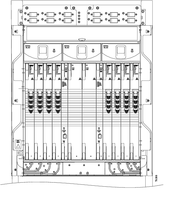
Figure 2-1  shows all of the cards installed in the shelf and the optical connectors.

Figure 2-1 ONS 15600 SDH with Optical Cards Installed

Step2 Remove the dust cap from the OGI connector adapter on the front of the card.

Step3 Plug the fiber into the transmit (Tx) connector of an STM-N port at one node by squeezing the latches on either side of the connector and gently pushing it into the faceplate connection point until the connector snaps into place.

Step4 Plug the other end of the fiber into the receive (Rx) connector of the same port number on an STM-N card at an adjacent node.


Note To create a 1+1 configuration, you must plug each end of the fiber-optic cable into the port of the same number on both cards; for instance, if you plug the Tx end of the cable into Port 1 you must plug the Rx end into Port 1 on another card installed in an adjacent node.


Step5 Repeat Steps 2 through 4 for each fiber-optic cable you require.

Step6 Return to your originating procedure (NTP).


DLP-F25 Install Fiber-Optic Cables for SNCP Configurations

Purpose

This task installs the fiber-optic cables to the subnetwork connection protection (SNCP) ports at each node. See "Turn Up Network" to provision and test SNCP configurations.

Tools/Equipment

Fiber-optic cables

Prerequisite Procedures

F11 Install the STM-N Cards

NTP-F94 Clean Fiber Connectors and Adapters, page 14-18

Required/As Needed

Required

Onsite/Remote

Onsite

Security Level

None


Caution To avoid loss of traffic, do not create an SNCP using two ports on the same card. You can create an SNCP on different ports on the same side of the shelf, but Cisco recommends using one port on one side of the shelf and another port on the opposite side.


Note See Table2-3 and Table2-4 for OGI connector pinouts of STM-N cards.


Step1 Plug the fiber into the Tx connector of an STM-N card at one node and plug the other end of the fiber into the Rx connector of an STM-N card at the adjacent node. The card will display a signal fail (SF) LED if the transmit and receive fibers are mismatched (one fiber connects a receive port on one card to a receive port on another card, or the same situation with transmit ports).

Step2 Repeat Step1 until you have configured the ring.

Step3 Return to your originating procedure (NTP).


DLP-F26 Install Fiber-Optic Cables for MS-SPRing Configurations

Purpose

This task installs the fiber-optics to the east and west multiplex section-shared protection ring (MS-SPRing) ports at each node. See "Turn Up Network" to provision and test MS-SPRing configurations.

Tools/Equipment

Fiber-optic cables

Prerequisite Procedures

F11 Install the STM-N Cards

NTP-F94 Clean Fiber Connectors and Adapters, page 14-18

Required/As Needed

As needed

Onsite/Remote

Onsite

Security Level

None


Caution Do not provision the MS-SPRing east and west ports on the same STM-N card.


Note To avoid error, connect fiber-optic cable so that the farthest slot to the right represents the east port, and the farthest slot to the left represents the west port. Fiber connected to an east port at one node must plug into the west port on an adjacent node.


Note See Table2-3 and Table2-4 for OGI connector pinouts of STM-N cards.


Step1 Plan your fiber connections. Use the same plan for all MS-SPRing nodes. MS-SPRing configuration is achieved by correctly cabling the transmit and receive fibers of each node to the others.

Step2 Plug the fiber into the Tx connector of an STM-N card at one node and plug the other end into the Rx connector of an STM-N card at the adjacent node. The card displays a SF LED if the transmit and receive fibers are mismatched.

Step3 Repeat Step2 until you have configured the ring.

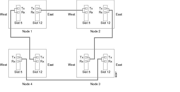
Figure 2-2  shows fiber connections for a two-fiber MS-SPRing with trunk cards in Slot 5 (west) and Slot 12 (east).

Figure 2-2 Connecting Fiber to a Four-Node, Two-Fiber MS-SPRing


Note To provision a MS-SPRing, see "Turn Up Network"


Step4 Return to your originating procedure (NTP).


DLP-F27 Route Fiber-Optic Cables

Purpose

This task explains how to route fiber-optic cables away from the card faceplates and onto the side of the shelf.

Tools/Equipment

Tie-wrap (Suggested: Panduit TAK-TAPE TTS-20R0 Nelcro tie-wraps)

Prerequisite Procedures

F16 Install the Fiber-Optic Cables

Required/As Needed

Required

Onsite/Remote

Onsite

Security Level

None


Step1 Open the fold-down front door on the cable-management tray.

Step2 For each optical card you plan to install, find the corresponding cable routing channel directly below that card ( Figure2-3.)

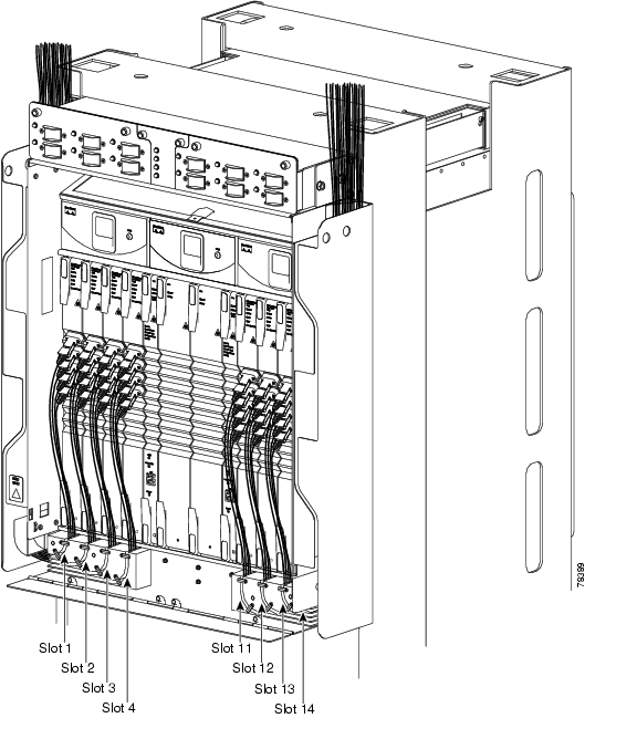
Figure 2-3 ONS 15600 SDH with All Optical Cards Cabled and Routed

Step3 Rotate the plastic cable latches for each optical card you will install to the open position so that they do not block the cable routing channels in the cable-management tray.

Step4 Route the fiber cable from the connector on the card through the corresponding cable routing channel in the cable-management tray. Start from the innermost card on one side of the shelf (Slot 4 on the left side, for instance).


Note If a slot is empty, leave the corresponding cable routing channel empty for later use.


Step5 If narrow cable routing modules (NCRMs) are installed:

a. Route the fiber cables through the cable-management tray toward the edge of the bay and then up through the NCRM attached to the side of the bay, inserting the fiber into the open tracks in the NCRM ( Figure 2-3 ). Make sure the cables line up directly in front of the corresponding card so the cables are not disturbed if later a card is removed.

b. Rotate the corresponding cable latch to the closed position so it secures the fiber cables within the corresponding cable routing channel.

c. Repeat Steps a  and b  for the fiber cables from each installed STM-N card, working from the innermost cards outward.

Step6 If wide CRMs are installed:

a. Gently pull the spool flanges toward you until they click open.

b. Route the fiber cables through the cable-management tray toward the edge of the bay and then up through the wide CRM attached to that side of the bay. Gently loop the cable around the spools. Store no more than one meter of slack (on average) for each cable that you route through the wide CRM.


Note If your site uses underfloor cabling, route the cables down to the CRM on the shelf directly below the node for which you are routing cables.


c. Rotate the corresponding cable latch to the closed position so it secures the fiber cables within the corresponding cable routing channel.

d. Repeat Steps a  through c  for the fiber cables from each installed STM-N card, working from the innermost cards outward. Distribute the cables as evenly as possible on the three storage spools of the CRM.

e. Push any extended spool flanges away from you so that they click closed.

f. Use tie wrap to secure the cable and minimize slack. Start with the cables closest to the outside edge of the CRM.

Step7 Make sure all the plastic cable latches are in the closed position.

Step8 Close the fold-down tray door when all fiber cables are properly routed.

Step9 Return to your originating procedure (NTP).


NTP-F17 Replace the Front Door

Purpose

This procedure explains how to reattach the front door of the ONS15600SDH.

Tools/Equipment

None

Prerequisite Procedures

F3 Open and Remove the Front Door

Required/As Needed

As needed

Onsite/Remote

Onsite

Security Level

None


Step1 Insert the front door in the hinges on the shelf assembly.

Step2 Lower the door onto the face of the ONS15600SDH.

Step3 Pull the metal latches on the door outward and gently push the door toward the shelf, making sure no optical cables are caught or pinched in the door.

Step4 Click the latches in place and release.

Stop. You have completed this procedure.


hometocprevnextglossaryfeedbacksearchhelp

Posted: Thu Feb 26 17:20:45 PST 2004
All contents are Copyright © 1992--2004 Cisco Systems, Inc. All rights reserved.
Important Notices and Privacy Statement.