|
|

Table Of Contents
F52 Common Control Card Switch Test
F53 Provision SDH DCC Terminations
F54 Change the Service State for a Port
F55 Optical 1+1 (LMSP) Manual Protection Switch Test
F57 MS-SPRing Exercise Ring Test
F59 SNCP Protection Switching Test
Turn Up Network
This chapter explains how to turn up and test CiscoONS15600SDH nodes in point-to-point networks, subnetwork connection protection rings (SNCPs), and multiplex section-shared protection rings (MS-SPRings).
Before You Begin
This section lists the chapter procedures (NTPs). Turn to a procedure for applicable tasks (DLPs).
1.
F32 Verify Node Turn Up—Complete this procedure before beginning network turn up.
2.
3.
4.
5.
6.
7.
8.
9.
NTP-F32 Verify Node Turn Up
Step1
Step2
Step3
Step4
a.
b.
Step5
Step6
Step7
Step8
Step9
Step10
Step11
Step12
Step13
Stop. You have completed this procedure.
DLP-F52 Common Control Card Switch Test
Step1
a.
b.
c.
d.
e.
f.
g.
h.
i.
j.
k.
l.
Step2
a.
b.
c.
d.
e.
•
•
f.
g.
h.
Step3
NTP-F33 Create a Logical Network Map
Step1
Step2
Step3
a.
b.
c.
Step4
Step5
CTC displays a progress bar and saves the new node positions.
Note
Stop. You have completed this procedure.
NTP-F34 Provision a Point-to-Point Connection
Step1
Step2
Step3
Step4
Step5
Step6
Note
Note
Step7
Step8
Step9
Stop. You have completed this procedure.
DLP-F53 Provision SDH DCC Terminations
Step1
Step2
Step3
Note
Step4
Step5
Step6
DLP-F54 Change the Service State for a Port
Step1
Step2
Step3
•
•
Step4
Step5
Step6
NTP-F35 Point-to-Point Network Acceptance Test
Step1
Step2
Step3
a.
b.
Step4
Step5
Step6
Step7
Step8
•
•
Step9
Step10
Step11
Note
Step12
a.
b.
Note
Step13
Step14
Step15
Step16
Step17
Step18
Step19
Step20
Step21
Step22
After all tests are successfully completed and no alarms exist in the network, the network is ready for service application.
Stop. You have completed this procedure.
DLP-F55 Optical 1+1 (LMSP) Manual Protection Switch Test
Step1
Step2
a.
b.
Step3
Step4
Step5
Step6
Step7
Step8
Step9
Protect port - Protect/Active [FORCE_SWITCH_TO_PROTECT], [PORT STATE]Working port - Working/Standby [FORCE_SWITCH_TO_PROTECT], [PORT STATE]Step10
Step11
Step12
Step13
Step14
Step15
Protect port - Protect/Standby [FORCE_SWITCH_TO_WORKING], [PORT STATE]Working port - Working/Active [FORCE_SWITCH_TO_WORKING], [PORT STATE]Step16
Step17
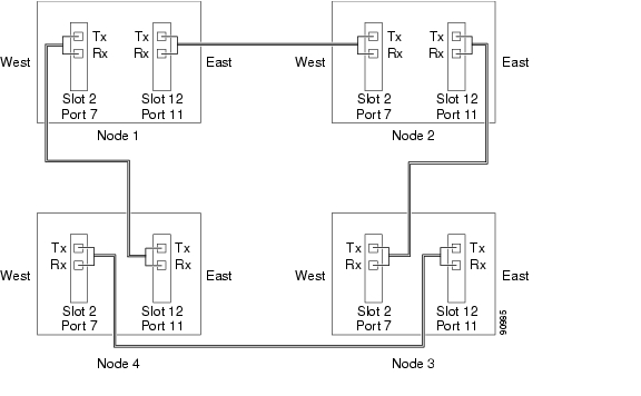
NTP-F36 Provision MS-SPRing Nodes
Step1
Figure 5-1 Four-Node, Two-Fiber MS-SPRing Fiber Connection Example
Step2
Step3
Note
Step4
Step5
Step6
Stop. You have completed this procedure.
DLP-F56 Remap the K3 Byte
Caution
Step1
Step2
Step3
Step4
Step5
Note
Step6
NTP-F37 Create an MS-SPRing
Step1
Step2
Step3
Step4
Step5
•
•
•
•
Step6
a.
b.
c.
d.
Step7
Step8
a.
b.
c.
d.
Note
Step9
•
•
Step10
Stop. You have completed this procedure.
NTP-F38 Two-Fiber MS-SPRing Acceptance Test
Note
Step1
Step2
Step3
a.
b.
Step4
Step5
Step6
Step7
Step8
Step9
Step10
Step11
Step12
Note
Step13
a.
b.
Note
Step14
Step15
Step16
Step17
Step18
Step19
Step20
Step21
After all tests are successfully completed and no alarms exist in the network, the network is ready for service application. Continue with "Create Circuits"
Stop. You have completed this procedure.
DLP-F57 MS-SPRing Exercise Ring Test
Step1
Step2
Step3
Step4
Note
Step5
Step6
On the network view graphic, an E appears on the working MS-SPRing channel where you invoked the protection switch. The E will display for 10 to 15 seconds, then disappear.
Step7
If you do not see any MS-SPRing exercise conditions, verify that the Filter button is not selected. Also, check that alarms and conditions are not suppressed for a node or MS-SPRing drop cards. See the "NTP-F57 Suppress and Restore Alarm Reporting" procedure for more information.
Step8
a.
b.
Step9
Step10
DLP-F58 MS-SPRing Switch Test
Step1
Step2
Step3
Note
Step4
Step5
On the network view graphic, an F appears on the MS-SPRing channel where you invoked the Force Ring switch. The MS-SPRing span lines turn purple where the switch was invoked, and all span lines between other MS-SPRing nodes turn green.
Step6
Step7
•
•
Note
Step8
•
•
Step9
Step10
a.
b.
•
•
•
Step11
Step12
a.
b.
Step13
Step14
Step15
Step16
On the network view graphic, the Force Ring switch is removed, the F indicating the switch is removed, and the span lines between MS-SPRing nodes will be purple and green. The span lines might take a few moments to change color.
Step17
Step18
a.
b.
Step19
Step20
Step21
On the network view graphic, an F appears on the working MS-SPRing channel where you invoked the Force Ring switch. The MS-SPRing span lines are purple where the Force Ring switch was invoked, and all span lines between other MS-SPRing nodes are green. The span lines might take a few moments to change color.
Step22
Step23
•
•
Note
Step24
•
•
Step25
Step26
a.
b.
•
•
•
Step27
Step28
Step29
Step30
Step31
Step32
On the network view graphic, the Force Ring switch is removed, the F indicating the switch is removed, and the span lines between MS-SPRing nodes will be purple and green. The span lines might take a few moments to change color.
Step33
Step34
a.
b.
Step35
Step36
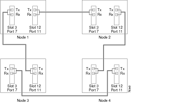
NTP-F39 Provision SNCP Nodes
Step1
Figure 5-2 SNCP Fiber Connection Example
Step2
Step3
Note
Step4
Step5
Step6
Stop. You have completed this procedure.
NTP-F40 SNCP Acceptance Test
Step1
Step2
Step3
a.
b.
Step4
Step5
Step6
Step7
Step8
Step9
Step10
Step11
a.
b.
Note
Step12
a.
b.
Note
Step13
Step14
Step15
Step16
Step17
Although a service interruption under 50 ms might occur, the test circuit should continue to work before, during, and after the switches. If the circuit stops working, do not continue. Contact your next level of support.
Step18
Step19
Step20
Step21
Step22
Step23
Step24
Step25
Step26
Step27
After all tests are successfully completed and no alarms exist in the network, the network is ready for service application.
Stop. You have completed this procedure.
DLP-F59 SNCP Protection Switching Test
Purpose
This task verifies SNCP protection switching.
Tools/Equipment
None
Prerequisite Procedures
Required/As Needed
Required
Onsite/Remote
Onsite
Security Level
Provisioning or higher
Step1
Step2
The Circuits on Span dialog box displays the SNCP circuits, including circuit names, location, and a color code showing which circuits are active on the span.
Step3
Caution
Step4
Note
Step5
Step6
Note
Step7
![]()
![]()
![]()
![]()
![]()
![]()
![]()
![]()
Posted: Thu Feb 26 17:30:47 PST 2004
All contents are Copyright © 1992--2004 Cisco Systems, Inc. All rights reserved.
Important Notices and Privacy Statement.