cc/td/doc/product/ong/600_sdh/sdh60014
hometocprevnextglossaryfeedbacksearchhelp
PDF

Table Of Contents

Add and Drop MS-SPRing and SNCP Nodes

Before You Begin

F135 Check MS-SPRing or SNCP for Alarms and Conditions

F136 Create an MS-SPRing on a Single Node

F137 Initiate an MS-SPRing Force Ring Switch

F138 Clear an MS-SPRing Force Ring Switch

F139 Verify MS-SPRing Pass-Through Circuits

F140 Verify MS-SPRing Extension Byte Mapping

F141 Delete an MS-SPRing from a Single Node

F143 Clear a Switch for all SNCP Circuits on a Span

F142 Switch All SNCP Circuits on a Span

F144 Verify Timing in a Reduced Ring

Add and Drop MS-SPRing and SNCP Nodes


This chapter explains how to add and remove CiscoONS15600SDH nodes from multiplex section-shared protection rings (MS-SPRings) and subnetwork connection protection (SNCP) rings.

Before You Begin

Refer to "Manage Alarms" to investigate all alarms, clear any trouble conditions, and manually document existing provisioning.

This section lists the chapter procedures (NTPs). Turn to a procedure for a list of its tasks (DLPs).

1. F83 Add an MS-SPRing Node—Complete as needed.

2. F84 Remove an MS-SPRing Node—Complete as needed.

3. F85 Add an SNCP Node—Complete as needed.

4. F86 Remove an SNCP Node—Complete as needed.

NTP-F83 Add an MS-SPRing Node

Purpose

This procedure expands an MS-SPRing by adding a node.

Tools/Equipment

Fiber for new node connections

Prerequisite Procedures

F37 Create an MS-SPRing

Required/As Needed

As needed

Onsite/Remote

Onsite

Security Level

Provisioning or higher


Note You can add only one node at a time. Perform these steps onsite and not from a remote location.


Caution Adding an MS-SPRing node can be service affecting and should be performed during a maintenance window.


Step1 Draw a diagram of the MS-SPRing where you will add the node. In the diagram, identify the east and west MS-SPRing STM-N trunk (span) cards/ports that will connect to the new node. This information is essential to complete this procedure without error. Figure13-1 shows a drawing of a three-node, two-fiber MS-SPRing that uses Slot 4/Port 1 and Slot 12/Port 3 for the MS-SPRing trunk cards/ports. The dashed arrow shows the new fiber connections that will be made to add the fourth node to the MS-SPRing.

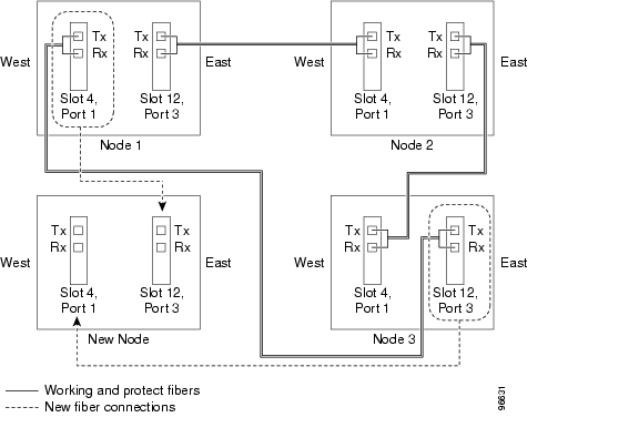
Figure 13-1 Three-Node, Two-Fiber MS-SPRing Before a Fourth Node Is Added

Step2 Verify the card installation in the new node using the "NTP-F22 Verify Card Installation" procedure on page4-2. Verify that the STM-N cards that will be the MS-SPRing trunk cards match the MS-SPRing optical rate. For example, if the MS-SPRing is STM-16, the new node must have STM-16 cards installed. If the STM-N cards are not installed or the optical rates do not match the MS-SPRing, complete the "NTP-F11 Install the STM-N Cards" procedure.

Step3 Verify that fiber is available to connect the new node to the existing nodes. Refer to the diagram drawn in Step1.

Step4 Complete the "NTP-F32 Verify Node Turn Up" procedure. In order to have Cisco Transport Controller (CTC) visibility to the new node after it is added, you must be an authorized user on the node and you must have IP connectivity to the node.

Step5 Check to see if the new node IP address is on the same subnet as other nodes in the network. If two or more PCs are directly connected to different nodes that belong to the same subnet and Craft Access Only is not checked under Gateway Settings, add static routes on the gateway ONS15600SDH nodes. Use the following settings:

Destination IP address: Local-PC-IP-address

Net Mask: 255.255.255.255

Next Hop: IP-address-of-the-Cisco-ONS-15600-SDH

Cost: 1

See the "DLP-F44 Create a Static Route" task on page 4-10 . To view Gateway Settings, see the "DLP-F43 Provision IP Settings" task on page 4-8 .

Step6 Log into a node that is in the MS-SPRing. See the "DLP-F36 Log into CTC" task.

Step7 Complete the "DLP-F135 Check MS-SPRing or SNCP for Alarms and Conditions" task to verify that the MS-SPRing is free of major alarms or problems. If trouble is indicated (for example, a major alarm exists), resolve the problem before proceeding. See "Manage Alarms" or, if necessary, refer to the CiscoONS15600SDH Troubleshooting Guide.

Step8 Click the Provisioning > MS-SPRing tabs.

Step9 On paper, record the Ring ID, Type, Rate, and Ring Reversion.

Step10 From the Node column, record the Node IDs in the MS-SPRing. The Node IDs are the numbers in parentheses next to the node name.

Step11 Log into the new node:

If the node has a LAN connection and appears on the network map, from the View menu, choose Go to Other Node , then enter the new node.

If the new node is not connected to the network, log into it using the "DLP-F36 Log into CTC" task .

Step12 Click the Alarms tab. Verify that no critical or major alarms are present, nor any facility alarms, such as LOS, LOF, MS-AIS, MS-EXC, or MS-DEG. If trouble is indicated (for example, a major alarm exists), resolve the problem before proceeding. See "Manage Alarms" or, if necessary, refer to the CiscoONS15600SDH Troubleshooting Guide.

Step13 Using the information recorded in Steps 9 and 10 and the diagram created in Step1, create an MS-SPRing on the new node. See the "DLP-F136 Create an MS-SPRing on a Single Node" task.

Step14 (Optional) Create test circuits, making sure they pass through the MS-SPRing trunk cards/ports, and run test traffic through the node to ensure the cards are functioning properly. See the "NTP-F43 Create a Manually Routed Optical Circuit" procedure.

Step15 Create the data communications channel (DCC) terminations on the new node. See the "DLP-F53 Provision SDH DCC Terminations" task.


Note Creating the DCC terminations causes the SDCC Termination Failure and Loss of Signal alarms to appear. These alarms will remain active until you connect the node to the MS-SPRing.


Note If you map the K3 byte to another byte (such as E2), you must remap the line cards on either side of the new node or span to the same byte. See the "DLP-F56 Remap the K3 Byte" task.


Step16 Log into an MS-SPRing node that will connect to the new node. See the "DLP-F36 Log into CTC" task.

Step17 Referring to the diagram created in Step1, complete the "DLP-F137 Initiate an MS-SPRing Force Ring Switch" task on the node that will connect to the new node via its west line (port).

Step18 Referring to the diagram created in Step1, complete the "DLP-F137 Initiate an MS-SPRing Force Ring Switch" task on the node that will connect to the new node via its east line (port).

Step19 Click the Alarms tab. If unexpected critical or major alarms appear, resolve them before you continue. If necessary, refer to the alarm troubleshooting procedures in the CiscoONS15600SDH Troubleshooting Guide.

Step20 Following the diagram created in Step1, remove the fiber connections from the two nodes that will connect to the new node.

a. Remove the west fiber from the node that will connect to the east port of the new node. In the Figure 13-1  example, this is Node 1/Slot 4/Port 1.

b. Remove the east fiber from the node that will connect to the west port of the new node. In the Figure 13-1  example, this is Node 3/Slot 12/Port 3.

Step21 Connect fibers from the adjacent nodes to the new node following the diagram created in Step1. Connect the west port of the new node to the east port of its connecting node and the east port of the new node to the west port of the its connecting node.


Warning Invisible laser radiation may be emitted from the end of the unterminated fiber cable or connector. Do not stare into the beam or view directly with optical instruments. Viewing the laser output with certain optical instruments (for example, eye loupes, magnifiers, and microscopes) within a distance of 100 mm may pose an eye hazard. Use of controls or adjustments or performance of procedures other than those specified may result in hazardous radiation exposure.


Step22 Display the newly added node in node view.

Step23 If the node does not appear, check DCC and fiber connections.

Step24 Click the Provisioning > MS-SPRing tabs.

Step25 Select the new MS-SPRing and click Ring Map . Verify that the new node appears on the Ring Map with the other MS-SPRing nodes, then click OK .

Step26 From the View menu, choose Go to Network View and check the following:

a. Click the Provisioning > MS-SPRing tabs. Verify that the new node appears in the Node column.

b. Click the Alarms tab. Verify that MS-SPRing alarms such as RING MISMATCH, E-W MISMATCH, PRC-DUPID (duplicate node ID), and APSCDFLTK (default K) do not appear.

If the new node does not appear in the Node column, or if MS-SPRing alarms are displayed, log into the new node and verify that the MS-SPRing is provisioned on it correctly with the information from Steps  9  and  10 . If the node still does not appear, or if alarms persist, refer to the Cisco ONS 15600 SDH Troubleshooting Guide.

Step27 Click the Circuits tab. Wait until all the circuits are discovered. The circuits that pass through the new node are incomplete.

Step28 In network view, right-click the new node and choose Update Circuits With The New Node from the shortcut menu. Verify that the number of updated circuits in the dialog box is correct.

Step29 If incomplete circuits still appear, refer to the CiscoONS15600SDH Troubleshooting Guide.

Step30 Click the History tab. Verify that MS-SPRing_RESYNC conditions are present for every node in the MS-SPRing.

Step31 Complete the "DLP-F138 Clear an MS-SPRing Force Ring Switch" task to remove the ring switch from the east MS-SPRing span.

Step32 Complete the "DLP-F138 Clear an MS-SPRing Force Ring Switch" task to remove the ring switch from the west MS-SPRing span.

Step33 Complete the "NTP-F38 Two-Fiber MS-SPRing Acceptance Test" procedure.

Stop. You have completed this procedure.


DLP-F135 Check MS-SPRing or SNCP for Alarms and Conditions

Purpose

This task checks an MS-SPRing or an SNCP for alarms and conditions before performing any major administrative change to the ring such as adding and removing nodes.

Tools/Equipment

None

Prerequisite Procedures

F36 Log into CTC

Required/As Needed

As needed

Onsite/Remote

Onsite

Security Level

Retrieve or higher


Step1 From the View menu, choose Go to Network View . Verify that all MS-SPRing or SNCP spans on the network map are green.

Step2 Click the Alarms tab. Verify that no critical or major alarms are present, nor any facility alarms, such as LOS, LOF, AIS-L, SF, and SD. In an MS-SPRing, these facility conditions might be reported as minor alarms. Make sure the Filter button in the lower right corner of the window is off (not indented).

Step3 Click the Conditions tab and click Retrieve Conditions. Verify that no ring switches are active. Make sure the Filter button in the lower right corner of the window is off (not indented).

Step4 Return to the originating procedure (NTP).


DLP-F136 Create an MS-SPRing on a Single Node

Purpose

This task creates an MS-SPRing on a single node. Use this task to add a node to an existing MS-SPRing or when you delete and then recreate an MS-SPRing temporarily on one node.

Tools/Equipment

None

Prerequisite Procedures

F36 Log into CTC

Required/As Needed

As needed

Onsite/Remote

Onsite

Security Level

Provisioning or higher


Step1 In node view, click the Provisioning > MS-SPRing tabs.

Step2 Click Create .

Step3 Click OK in the Suggestion box if it appears.

Step4 In the Create MS-SPRing dialog box, enter the MS-SPRing information:

Ring ID—Enter the MS-SPRing ring ID.

Node ID—Enter the node ID. Use an ID that is not used by other MS-SPRing nodes.

Ring Reversion—Enter the ring reversion time of the existing MS-SPRing.

West Line—Select the slot/port on the node that will connect to the existing MS-SPRing via the node's west line (port).

East Line—Select the slot/port on the node that will connect to the existing MS-SPRing via the node's east line (port).

Step5 Click OK .


Note Alarms appear and the MS-SPRing is Incomplete until the node is connected to other MS-SPRing nodes.


Step6 Return to your originating procedure (NTP).


DLP-F137 Initiate an MS-SPRing Force Ring Switch

Purpose

This task initiates a Force Ring external switching command on an MS-SPRing port.

Tools/Equipment

None

Prerequisite Procedures

F36 Log into CTC

Required/As Needed

As needed

Onsite/Remote

Onsite

Security Level

Provisioning or higher


Caution The Force Switch Away command overrides normal protective switching mechanisms. Applying this command incorrectly can cause traffic outages.


Caution Traffic is not protected during a Force protection switch.


Step1 From the View menu, choose Go to Network View .

Step2 Click the Provisioning > MS-SPRing tabs. Select the MS-SPRing.

Step3 Click Edit .


Note If node icons overlap, drag and drop the icons to a new location. You can also return to network view and change the positions of the network node icons. MS-SPRing node icons are based on the network view node icon positions.


Step4 To apply a Force switch to the west line:

a. Right-click the west MS-SPRing port where you want to switch the MS-SPRing traffic and choose Set West Protection Operation .


Note For two-fiber MS-SPRings, the squares on the node icons represent the MS-SPRing working and protect channels. You can right-click either channel.


b. In the Set West Protection Operation dialog box choose FORCE RING from the drop-down menu. Click OK .

c. Click Yes in the two Confirm MS-SPRing Operation dialog boxes that appear.

On the network graphic, an F appears on the working MS-SPRing channel where you invoked the protection switch. The span lines change color to reflect the forced traffic. Green span lines indicate the new MS-SPRing path, and the lines between the protection switch are purple.

Performing a Force switch generates several conditions including FORCED-REQ-RING and WKSWPR.

Step5 To apply a Force switch to the east line:

a. Right-click the east MS-SPRing port and choose Set East Protection Operation .


Note If node icons overlap, drag and drop the icons to a new location or return to network view and change the positions of the network node icons. MS-SPRing node icons are based on the network view node icon positions.


Note For two-fiber MS-SPRings, the squares on the node icons represent the MS-SPRing working and protect channels. You can right-click either channel.


b. In the Set East Protection Operation dialog box, choose FORCE RING from the drop-down menu. Click OK .

c. Click Yes in the two Confirm MS-SPRing Operation dialog boxes that appear.

On the network graphic, an F appears on the working MS-SPRing channel where you invoked the protection switch. The span lines change color to reflect the forced traffic. Green span lines indicate the new MS-SPRing path, and the lines between the protection switch are purple.

Performing a Force switch generates several conditions including FORCED-REQ-RING and WKSWPR.

Step6 From the File menu, choose Close .

Step7 Return to your originating procedure (NTP).


DLP-F138 Clear an MS-SPRing Force Ring Switch

Purpose

This task removes the Force Ring external switching command from an MS-SPRing port.

Tools/Equipment

None

Prerequisite Procedures

F36 Log into CTC

Required/As Needed

As needed

Onsite/Remote

Onsite

Security Level

Provisioning or higher


Step1 From the View menu, choose Go to Network View .

Step2 Click the Provisioning > MS-SPRing tabs.

Step3 Select the MS-SPRing and click Edit .


Note If node icons overlap, drag and drop the icons to a new location or return to network view and change the positions of the network node icons. MS-SPRing node icons are based on the network view node icon positions.


Step4 To clear a Force switch on the west line:

a. Right-click the MS-SPRing west port where you want to clear the protection switch and choose Set West Protection Operation . Ports with a Force switch applied are marked with an F.

b. In the Set West Protection Operation dialog box, choose CLEAR from the drop-down menu. Click OK .

c. In the Confirm MS-SPRing Operation dialog box, click Yes .

Step5 To clear a Force switch on the east line:

a. Right-click the MS-SPRing east port where you want to clear the protection switch and choose Set East Protection Operation . Ports with a Force switch applied are marked with an F.

b. In the Set East Protection Operation dialog box, choose CLEAR from the drop-down menu. Click OK .

c. In the Confirm MS-SPRing Operation dialog box, click Yes .

On the MS-SPRing network graphic, a green and a purple span line connects each node. This is normal for MS-SPRings when protection operations are not invoked.

Step6 From the File menu, choose Close .

Step7 Return to your originating procedure (NTP).


NTP-F84 Remove an MS-SPRing Node

Purpose

This procedure removes a node from an MS-SPRing.

Tools/Equipment

None

Prerequisite Procedures

F37 Create an MS-SPRing

Required/As Needed

As needed

Onsite/Remote

Onsite

Security Level

Provisioning or higher


Caution The following procedure minimizes traffic outages during node removal. You will delete all circuits that originate and terminate on the node that will be removed. In addition, you will verify that circuits passing through the node do not enter and exit the node on different VC4s. If they do, you will delete and recreate the circuits, and traffic will be lost on that circuit during this time.


Step1 Complete the "DLP-F36 Log into CTC" task at the node you want to remove from the MS-SPRing.

Step2 Create a diagram of the MS-SPRing where you will remove the node. You can draw the MS-SPRing manually or print it from CTC by completing the "DLP-F65 Print CTC Data" task.

Step3 Referring to the MS-SPRing diagram, identify the following:

The node that is connected via its west port to the target (removal) node. For example, if you were removing Node 4 in Figure 13-2 , Node 1 is the node connected via its west port to Node 4.

The node that is connected via its east port to the target (removal) node. In Figure 13-2 , Node 3 is the node connected via its east port to Node 4.

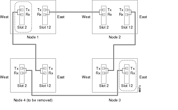
Figure 13-2 Four-Node, Two-Fiber MS-SPRing Before a Node Is Removed

Step4 Complete the "DLP-F135 Check MS-SPRing or SNCP for Alarms and Conditions" task to verify that the MS-SPRing is free of alarms. If trouble is indicated (for example, a major alarm exists), resolve the problem before proceeding. See "Manage Alarms" or, if necessary, refer to the CiscoONS15600SDH Troubleshooting Guide.

Step5 From the View menu, choose Go to Other Node . Choose the node that you will remove and click OK .

Step6 Click the Circuits tab. If the Scope setting is set to Network, choose Node from the Scope drop-down menu. Make sure the Filter button is off (not indented) to ensure that all circuits are visible.

Step7 Delete all circuits that originate or terminate on the node. See the "DLP-E97 Delete Circuits" task.

Step8 Complete the "DLP-F139 Verify MS-SPRing Pass-Through Circuits" task to verify that circuits passing through the target node enter and exit the node on the same VC4.

Step9 Complete the "DLP-F140 Verify MS-SPRing Extension Byte Mapping" task.

Step10 Referring to the diagram created in Step1, complete the "DLP-F137 Initiate an MS-SPRing Force Ring Switch" task at each node that connects to the target (removal) node to force traffic away from it. You must perform a Force switch at each port connected to the target node. For example, in Figure13-2, you would perform a Force switch on the east port of Node 3 and the west port of Node 1.

Step11 Click the Alarms tab. If unexpected critical or major alarms appear, resolve them before you continue. If necessary, refer to the alarm troubleshooting procedures in the CiscoONS15600SDH Troubleshooting Guide.

Step12 Remove the fiber connections between the target node and the two neighboring nodes.


Warning Invisible laser radiation may be emitted from the end of the unterminated fiber cable or connector. Do not stare into the beam or view directly with optical instruments. Viewing the laser output with certain optical instruments (for example, eye loupes, magnifiers, and microscopes) within a distance of 100 mm may pose an eye hazard. Use of controls or adjustments or performance of procedures other than those specified may result in hazardous radiation exposure.


Step13 Reconnect the fiber of the two neighboring nodes directly, west port to east port. For example in Figure13-2, the east port of Node 3 (Slot 12) connects to the west port of Node 1 (Slot 2).

Step14 Complete the "DLP-F141 Delete an MS-SPRing from a Single Node" task.

Step15 If you delete a node that was in a login node group, you will see incomplete circuits for that node in the CTC network view. (Although it is no longer part of the ring, the removed node still reports to CTC until it is no longer in a login node group.) Delete the node from the login node group:

a. From the CTC Edit menu, choose Preferences .

b. In the Preferences dialog box, click the Login Node Groups tab.

c. Click the login node group tab containing the node you want to remove.

d. Click the node you want to remove, then click Remove .

e. Click OK .

Step16 Complete the "DLP-F138 Clear an MS-SPRing Force Ring Switch" task to remove the Force protection switches.

Step17 Complete the "NTP-F38 Two-Fiber MS-SPRing Acceptance Test" procedure.

Stop. You have completed this procedure.


DLP-F139 Verify MS-SPRing Pass-Through Circuits

Purpose

This task verifies that circuits passing through a node that will be removed from an MS-SPRing enter and exit the node on the same VC4.

Tools/Equipment

None

Prerequisite Procedures

F36 Log into CTC

Required/As Needed

As needed

Onsite/Remote

Onsite or remote

Security Level

Provisioning or higher


Step1 In the Circuits window, choose a circuit that passes through the MS-SPRing node that will be removed and click Edit .

Step2 In the Edit Circuits window, check Show Detailed Map .

Step3 Verify that the VC4 mapping on the node's east and west ports is the same. For example, if a circuit is mapping on the west port s2/p1/V1 (Slot 2, Port 1, VC4 1), verify that the mapping is VC4 1 on the east port. If the circuit displays different VC4s on the east and west ports, write down the name of the circuit.

Step4 Repeat Steps 1 to 3 for each circuit in the Circuits tab.

Step5 Delete and recreate each circuit recorded in Step 3 that entered/exited the node on different VC4s. To delete the circuit, see the "DLP-E97 Delete Circuits" task. To create the circuit, see "Create Circuits"

Step6 Return to your originating procedure (NTP).


DLP-F140 Verify MS-SPRing Extension Byte Mapping

Purpose

This task verifies that the extension byte mapping is the same on MS-SPRing trunk (span) cards that will be connected after a node is removed from an MS-SPRing.

Tools/Equipment

STM-N cards must be installed at one or both ends of the MS-SPRing span that will be connected.

Prerequisite Procedures

F36 Log into CTC

Required/As Needed

As needed

Onsite/Remote

Onsite or remote

Security Level

Provisioning or higher


Step1 In network view, double-click one of the MS-SPRing nodes with STM-N trunk cards that will be reconnected after an MS-SPRing node removal.

Step2 Double-click one STM-N MS-SPRing trunk card to open the card view.

Step3 Click the Provisioning > MS tab.

Step4 Under MS-SPRing Ext Byte, record the byte that is displayed.

Step5 Repeat Steps 2 through 4 for the second STM-N trunk card.

Step6 If the trunk cards on each end of the new span are not mapped to the same MS-SPRing extension byte, remap the extension byte of the trunk cards at one of the nodes. See the "DLP-F56 Remap the K3 Byte" task.

Step7 Return to your originating procedure (NTP).


DLP-F141 Delete an MS-SPRing from a Single Node

Purpose

This task deletes an MS-SPRing from a node after you remove the node from the MS-SPRing.

Tools/Equipment

None

Prerequisite Procedures

F36 Log into CTC

Required/As Needed

As needed

Onsite/Remote

Onsite or remote

Security Level

Provisioning or higher


Step1 In network view, double-click the node that was removed from the MS-SPRing. If you are already in node view, continue with Step 2.

Step2 Click the Provisioning > MS-SPRing tabs.

Step3 Highlight the ring and click Delete .

Step4 In the Suggestion dialog box, click OK .

Step5 In the confirmation message, confirm that this is the ring you want to delete. If so, click Yes .

Step6 Return to your originating procedure (NTP).


NTP-F85 Add an SNCP Node

Purpose

This procedure adds a node to an existing SNCP.

Tools/Equipment

None

Prerequisite Procedures

F39 Provision SNCP Nodes

Required/As Needed

As needed

Onsite/Remote

Onsite

Security Level

Provisioning or higher


Note You can add only one node at a time. Perform these steps onsite and not from a remote location.


Step1 Verify the card installation on the new node. See the "NTP-F22 Verify Card Installation" procedure on page4-2. Check that the STM-N cards that will serve as the SNCP line cards match the SNCP optical rate. For example, if the SNCP is STM-16, the new node must have STM-16 cards installed. If the STM-N cards are not installed or the rate does not match the SNCP, complete the "NTP-F11 Install the STM-N Cards" procedure to install them.

Step2 Verify that fiber is available to connect the new node to the existing nodes.

Step3 Complete the "NTP-F32 Verify Node Turn Up" procedure.

Step4 Log into a node in the network where you want to add an SNCP node. See the "DLP-F36 Log into CTC" task for instructions. In order to have CTC visibility to the node after it is added, you must be an authorized user on the node and you must have IP connectivity to the node.

Step5 Check to see if the new node IP address is on the same subnet as other nodes in the network. If two or more PCs are directly connected to different nodes that belong to the same subnet and Craft Access Only is not checked under Gateway Settings, add static routes on the gateway ONS15600SDH nodes. Use the following settings:

Destination IP address: Local-PC-IP-address

Net Mask: 255.255.255.255

Next Hop: IP-address-of-the-Cisco-ONS-15600-SDH

Cost: 1

See the "DLP-F44 Create a Static Route" task on page 4-10 .

Step6 Complete the "DLP-F135 Check MS-SPRing or SNCP for Alarms and Conditions" task.

If trouble is indicated (for example, a major alarm exists), resolve the problem before proceeding. See "Manage Alarms,"  or, if necessary, refer to the Cisco ONS 15600 SDH Troubleshooting Guide.

Step7 Log into the new node. If the node has a LAN connection and appears on the network map, from the View menu, choose Go to Other Node , then enter the new node. If the new node is not connected to the network, you will need to log into it directly. See the "DLP-F36 Log into CTC" task.

Step8 Click the Alarms tab. Verify that no critical or major alarms are present, nor any facility alarms, such as LOS, LOF, AIS-L, SF, or SD. If trouble is indicated (for example, a major alarm exists), resolve the problem before proceeding. See "Manage Alarms," or, if necessary, refer to the CiscoONS15600SDH Troubleshooting Guide.

Step9 (Optional) Create test circuits, making sure they pass through the SNCP line cards, and run test traffic through the node to ensure the cards are functioning properly. See the "NTP-F43 Create a Manually Routed Optical Circuit" procedure.

Step10 Create the DCC terminations on the new node. See the "DLP-F53 Provision SDH DCC Terminations" task.

Step11 Complete the "DLP-F142 Switch All SNCP Circuits on a Span" task to switch traffic away from the span that will be broken to connect to the new node.


Caution Traffic is not protected during a protection switch.


Warning Invisible laser radiation may be emitted from the end of the unterminated fiber cable or connector. Do not stare into the beam or view directly with optical instruments. Viewing the laser output with certain optical instruments (for example, eye loupes, magnifiers, and microscopes) within a distance of 100 mm may pose an eye hazard. Use of controls or adjustments or performance of procedures other than those specified may result in hazardous radiation exposure.


Step12 Two nodes will connect directly to the new node; remove their fiber connections:

a. Remove the east fiber connection from the node that will connect to the west port of the new node.

b. Remove the west fiber connection from the node that will connect to the east port of the new node.

Step13 Replace the removed fibers with fibers connected to the new node.

Step14 Check to see if your new node's IP address is on the same subnet as other nodes in the network. If two or more PCs are directly connected to different nodes that belong to the same subnet, you need to add static routes on the gateway ONS15600SDH nodes. Use the following settings:

Destination IP address: Local-PC-IP-address

Net Mask: 255.255.255.255

Next Hop: IP-address-of-the-Cisco-ONS-15600-SDH

Cost: 1

See the "DLP-F44 Create a Static Route" task on page 4-10 .

Step15 Log out of CTC and log back into a node in the network. See the "DLP-F36 Log into CTC" task for instructions.

Step16 From the View menu choose Go to Network View to display the SNCP nodes. The new node should appear in the network map. Wait for a few minutes to allow all the nodes to appear.

Step17 Click the Circuits tab and wait for all the circuits to appear, including spans. Count the number of incomplete circuits.

Step18 In the network view, right-click the new node and choose Update Circuits With New Node from the list of options. Wait for the confirmation dialog box to appear. Verify that the number of updated circuits displayed in the dialog box is correct.

Step19 Click the Circuits tab and verify that no incomplete circuits are present.

Step20 Use the "DLP-F143 Clear a Switch for all SNCP Circuits on a Span" task to clear the protection switch.


Note This will clear switches for both spans.


Step21 Complete the "NTP-F40 SNCP Acceptance Test" procedure.

Stop. You have completed this procedure.


DLP-F143 Clear a Switch for all SNCP Circuits on a Span

Purpose

This task clears a Force traffic switch for all circuits on an SNCP span.

Tools/Equipment

None

Prerequisite Procedures

F36 Log into CTC

Required/As Needed

As needed

Onsite/Remote

Onsite

Security Level

Provisioning or higher


Step1 From the View menu, choose Go To Network View .

Step2 Right-click the span where you want to clear the switch ( Figure13-3).

Step3 Choose Circuits from the shortcut menu.

Step4 In the Circuits on Span dialog box, select CLEAR to remove a previously set switch command.

Step5 In the confirmation dialog box, click Yes .

In the Circuits on Span dialog box, the Switch State listed for all circuits is CLEAR.

Step6 Return to your originating procedure (NTP).


NTP-F86 Remove an SNCP Node

Purpose

This procedure removes a node from an SNCP.

Tools/Equipment

None

Prerequisite Procedures

F39 Provision SNCP Nodes

Required/As Needed

As needed

Onsite/Remote

Onsite

Security Level

Provisioning or higher


Caution The following procedure minimizes traffic outages during node removals. You will delete all circuits that originate and terminate on the node that will be removed.


Caution If you remove a node that is the only building integrated timing supply (BITS) timing source for the ring, you will remove the only source of synchronization for all the nodes in that ring. Circuits that leave the ring to connect to other networks that are synchronized to Stratum 1 will experience a high level of pointer adjustments, which might adversely affect customer service.


Step1 Draw a diagram of the SNCP where you will remove the node. In the diagram, identify the following:

The node that is connected through its west port to the node that will be removed.

The node that is connected through its east port to the node that will be removed.

Step2 Complete the "DLP-F36 Log into CTC" task at a node in the network where you will remove the SNCP node.

Step3 Complete the "DLP-F135 Check MS-SPRing or SNCP for Alarms and Conditions" task.

Step4 At each SNCP node, ensure that all fibers are securely connected to the appropriate ports.

If trouble is indicated (for example, a critical or major alarm exists), resolve the problem before proceeding. Refer to the Cisco ONS 15600 SDH Troubleshooting Guide.

Step5 Complete the "DLP-F142 Switch All SNCP Circuits on a Span" task for all spans connected to the node you are removing.


Caution Traffic is not protected during a Force protection switch.


Step6 See the "DLP-E97 Delete Circuits" task and "Create Circuits" to delete and recreate each circuit that passed through the deleted node on different VC4s.

Step7 Remove all fiber connections between the node being removed and the two neighboring nodes.

Step8 Reconnect the fiber of the two neighboring nodes directly, west port to east port.


Warning Invisible laser radiation may be emitted from the end of the unterminated fiber cable or connector. Do not stare into the beam or view directly with optical instruments. Viewing the laser output with certain optical instruments (for example, eye loupes, magnifiers, and microscopes) within a distance of 100 mm may pose an eye hazard. Use of controls or adjustments or performance of procedures other than those specified may result in hazardous radiation exposure.


Step9 If you delete a node that was in a login node group, you will see incomplete circuits for that node in the CTC network view. (Although it is no longer part of the ring, the removed node still reports to CTC until it is no longer in a login node group.) Delete the node from the login node group:

a. From the CTC Edit menu, choose Preferences .

b. In the Preferences dialog box, click the Login Node Groups tab.

c. Click the login node group tab containing the node you want to remove.

d. Click the node you want to remove, then click Remove .

e. Click OK .

Step10 Exit CTC and log back in. See the "DLP-F36 Log into CTC" task for instructions.

Step11 Complete the "DLP-F135 Check MS-SPRing or SNCP for Alarms and Conditions" task.

Step12 See the "DLP-E97 Delete Circuits" task and "Create Circuits" to delete and recreate each circuit that passed through the deleted node on different VC4s.

Step13 Complete the "DLP-F144 Verify Timing in a Reduced Ring" task.

Step14 Complete the "DLP-F143 Clear a Switch for all SNCP Circuits on a Span" task to clear the protection switch.

Step15 Click the Circuits tab and verify that no incomplete circuits are present.

Step16 Complete the "NTP-F40 SNCP Acceptance Test" procedure.

Stop. You have completed this procedure.


DLP-F142 Switch All SNCP Circuits on a Span

Purpose

This task applies a Force external switching command to all circuits on an SNCP span. The Force switches the traffic to another span.

Tools/Equipment

None

Prerequisite Procedures

F36 Log into CTC

Required/As Needed

As needed

Onsite/Remote

Onsite

Security Level

Provisioning or higher


Step1 From the View menu, choose Go To Network View.

Step2 Right-click the span where you want to switch SNCP traffic ( Figure13-3).

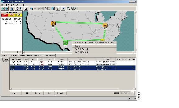
Figure 13-3 Using the Span Shortcut Menu to Display Circuits

Step3 Choose Circuits from the shortcut menu.

Step4 In the Circuits on Span dialog box, select Force Switch Away ( Figure13-4).


Caution The Force command overrides normal protective switching mechanisms. Applying this command incorrectly can cause traffic outages.


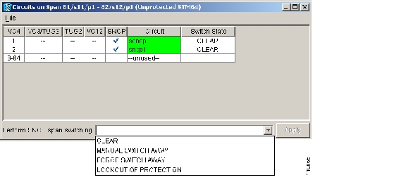
Figure 13-4 Switching an SNCP Path

Step5 In the confirmation dialog box, click Yes .

In the Circuits on Span dialog box, the Switch State listed for all circuits is FORCE.

Step6 Return to your originating procedure (NTP).


DLP-F144 Verify Timing in a Reduced Ring

Purpose

This task verifies timing in a reduced ring.

Tools/Equipment

None

Prerequisite Procedures

F36 Log into CTC

Required/As Needed

As needed

Onsite/Remote

Onsite/remote

Security Level

Provisioning or higher


Step1 In node view, click the Provisioning > Timing tabs.

Step2 Observe the Timing Mode field to see the type of timing (Line, External) that has been set for that node.

Step3 Scroll down to the Reference Lists and observe the NE Reference fields to see the timing references provisioned for that node.

Step4 If the removed node was the BITS timing source, perform the following:

a. Look for another node on the ring that can be used as a BITS source and set that node's Timing Mode to External . Choose that node as the primary timing source for all other nodes in the ring. See the "DLP-F118 Change the Node Timing Source" task .

b. If no node in the reduced ring can be used as a BITS source, choose one node to be your internal timing source. Set that node's Timing Mode to External and set the BITS 1 and 2 State to OOS . Then, choose line timing for all other nodes in the ring. This will force the first node to be their primary timing source. See the "DLP-F118 Change the Node Timing Source" task .


Note This type of timing conforms to Stratum 3E requirements and is not considered optimal.


Step5 If the removed node was not the BITS timing source, provision the adjacent nodes to line timing using SDH links (east and west) as timing sources, traceable to the node with external BITS timing.

Step6 Return to your originating procedure (NTP).


hometocprevnextglossaryfeedbacksearchhelp

Posted: Thu Feb 26 21:50:34 PST 2004
All contents are Copyright © 1992--2004 Cisco Systems, Inc. All rights reserved.
Important Notices and Privacy Statement.