|
|

Table Of Contents
F145 Initiate a Manual Switch on a Port in a 1+1 Protection Group
F146 Initiate a Force Switch on a Port in a 1+1 Protection Group
F147 Clear a Manual or Force Switch in a 1+1 Protection Group
F148 Apply a Lockon in a 1+1 Group
F149 Apply a Lockout in a 1+1 Group
F150 Clear a Lockon or Lockout in a 1+1 Protection Group
F151 Initiate a Manual Switch on an SNCP Circuit
F152 Initiate a Force Switch to an SNCP Circuit
F153 Initiate a Lockout on an SNCP Path
F154 Clear a Switch or Lockout on an SNCP Circuit
F157 Manually Switch the Node Timing Reference
F158 Clear a Manual Switch on a Node Timing Reference
Maintain the Node
This chapter provides procedures for maintaining the CiscoONS15600SDH.
Before You Begin
Before performing any of the following procedures, investigate all alarms and clear any trouble conditions. Refer to the CiscoONS15600 SDH Troubleshooting Guide as necessary. This section lists the chapter procedures (NTPs). Turn to a procedure to view its tasks (DLPs).
1.
F87 Inspect and Replace the Disposable Air Filter—Complete as needed.
2.
3.
4.
5.
6.
7.
8.
9.
10.
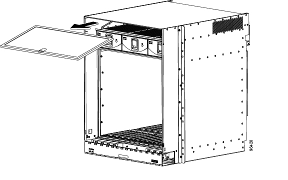
NTP-F87 Inspect and Replace the Disposable Air Filter
Step1
Step2
a.
b.
c.
d.
Step3
Figure 14-1 Removing a Disposable Air Filter (Front Door Removed)
Step4
Step5
Step6
a.
b.
c.
d.
Stop. You have completed this procedure.
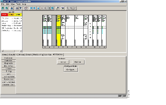
NTP-F88 Back Up the Database
Note
Note
Step1
Step2
Figure 14-2 Backing Up the TSC Database
Step3
Step4
Step5
Note
Step6
Step7
Note
Step8
Step9
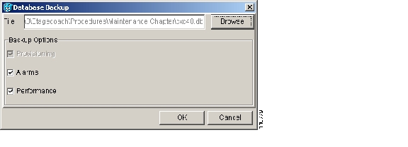
Step10
Figure 14-3 Database Filename Entered and Backup Options Checked
Stop. You have completed this procedure.
NTP-F89 Restore the Database
Purpose
This procedure restores the TSC software database.
Tools/Equipment
None
Prerequisite Procedures
Required/As Needed
As needed
Onsite/Remote
Onsite or remote
Security Level
Superuser
Note
Note
Note
Step1
Step2
Figure 14-4 Restoring a Backup TSC Database to the Node
Step3
Step4
Note
Step5
Step6
The file has a .db extension.
Step7
Step8
Figure 14-5 Restoring the Database: Traffic Loss Warning
Step9
The Database Restore window monitors the file transfer. Wait for the file to complete the transfer to the TSC.
Step10
Stop. You have completed this procedure.
NTP-F90 Initiate a Manual or Force Switch in a 1+1 Protection Group
Step1
Step2
Step3
Step4
Stop. You have completed this procedure.
DLP-F145 Initiate a Manual Switch on a Port in a 1+1 Protection Group
Step1
Step2
In the Selected Group area, each port is identified as Working or Protect. Each port also has a status:
•
•
•
•
•
•
The normal assignment status is for one port assignment to be Working/Active and for the other to be Protect/Standby.
Step3
Step4
If the Manual switch is successful, CTC shows both ports as [MANUAL TO PROTECT] (or [MANUAL TO WORKING]). This indicates that the ONS 15600 SDH system has been able to carry out the switch request and has moved traffic from one port to the other.
If the Bidirectional switching check box on the Provisioning > Protection tab in node view is checked, both the near-end and far-end nodes switch to the designated protection ports. For example, if the near-end node has a loss of signal (LOS), it switches to the protection port and transmits a switch request to the far-end node to switch to the protection port also. This ensures that both nodes process traffic from the same span.
If the Bidirectional switching check box is not selected, the near-end and far-end nodes switch independently of each other. For example, if the near-end node has an LOS on its working port, it switches to the protection port. If the far-end node does not have a LOS, traffic remains on the working port.
If the Manual switch is not successful, CTC continues to show the ports as active and standby, and an alarm such as FAILTOSWS is raised. This failure occurs because the target port is not available and troubleshooting is required. For information about troubleshooting, refer to the Cisco ONS 15600 SDH Troubleshooting Guide.
Step5
Step6
If any traffic loss alarms occur or if a switching failure alarm such as FAILTOSWS occurs, troubleshoot the alarms that have prevented the switch and attempt the switch procedure again.
Step7
DLP-F146 Initiate a Force Switch on a Port in a 1+1 Protection Group
Step1
Step2
In the Selected Group area, each port is identified as Working or Protect. Each port also has a status:
•
•
•
•
•
•
The normal status is for one port to be Working/Active and the other to be Protect/Standby.
Step3
Step4
If the Force switch is successful, CTC shows both ports as [FORCE TO PROTECT] (or [FORCE TO WORKING]). This indication is shown whether or not the ONS 15600 SDH system has been able to move traffic from one port to the other.
If the Bidirectional switching check box in node view under Provisioning > Protection tabs, is checked, both the near-end and far-end nodes switch to the designated protection ports. For example, if the near-end node has a LOS, it switches to the protection port and transmits a switch request to the far-end node to switch to the protection port also. This ensures that both nodes process traffic from the same span.
If the Bidirectional switching check box is not selected, the near-end and far-end nodes switch independently of each other. For example, if the near-end node has an LOS on its working port, it switches to the protection port. If the far-end node does not have a LOS, traffic remains on the working port.
If the Force switch is unsuccessful, clear the switch immediately using the "DLP-F147 Clear a Manual or Force Switch in a 1+1 Protection Group" task , and then troubleshoot the problems preventing the switch by referring to the Cisco ONS 15600 SDH Troubleshooting Guide.
Step5
Step6
No new traffic loss alarms or failure-to-switch alarms should have been raised.
Step7
DLP-F147 Clear a Manual or Force Switch in a 1+1 Protection Group
Purpose
For ports configured for revertive switching, this task clears the Manual or Force switch and restores traffic to the preswitch port. For nonrevertive ports, it clears the switch but does not revert traffic to the previous port.
Tools/Equipment
None
Prerequisite Procedures
F145 Initiate a Manual Switch on a Port in a 1+1 Protection Group or
F146 Initiate a Force Switch on a Port in a 1+1 Protection Group
Required/As Needed
As needed
Onsite/Remote
Onsite or remote
Security Level
Provisioning or higher
Step1
Step2
Step3
Step4
Step5
The Manual or Force switch is cleared.
Step6
NTP-F91 Inhibit Protection Switching in a 1+1 Protection Group
Step1
Step2
Step3
Step4
Note
Stop. You have completed this procedure.
DLP-F148 Apply a Lockon in a 1+1 Group
Note
Step1
Step2
Step3
a.
b.
Step4
Step5
Step6
The lockon has been applied and traffic cannot be switched from that port. See the "DLP-F150 Clear a Lockon or Lockout in a 1+1 Protection Group" task as needed.
Step7
DLP-F149 Apply a Lockout in a 1+1 Group
Note
Step1
Step2
Step3
Step4
Step5
The lockout has been applied and traffic is switched to the opposite card. To clear the lockout, see the "DLP-F150 Clear a Lockon or Lockout in a 1+1 Protection Group" task .
Step6
DLP-F150 Clear a Lockon or Lockout in a 1+1 Protection Group
Purpose
This task clears the lockon or lockout to resume normal protection switching capability.
Tools/Equipment
None
Prerequisite Procedures
F148 Apply a Lockon in a 1+1 Group or
Required/As Needed
As needed
Onsite/Remote
Onsite or remote
Security Level
Provisioning or higher
Step1
Step2
Step3
Step4
Step5
The lockon or lockout is cleared.
Step6
NTP-F92 Initiate an External Switching Command on an SNCP Circuit
Note
Step1
Step2
Step3
Step4
Step5
Note
Stop. You have completed this procedure.
DLP-F151 Initiate a Manual Switch on an SNCP Circuit
Step1
Step2
Step3
Step4
Step5
Step6
Traffic switches from the working SNCP path to the protect path. If the path is configured for revertive switching, the traffic reverts to the working path when the Manual switch is cleared. See the "DLP-F154 Clear a Switch or Lockout on an SNCP Circuit" task as needed.
Step7
DLP-F152 Initiate a Force Switch to an SNCP Circuit
Step1
Step2
Step3
Step4
Step5
Step6
Traffic switches from the protect path to the working path. Protection switching cannot occur until the Force switch is cleared. See the "DLP-F154 Clear a Switch or Lockout on an SNCP Circuit" task as needed.
Step7
DLP-F153 Initiate a Lockout on an SNCP Path
Step1
Step2
Step3
Step4
Note
Step5
Working traffic is prevented from switching to the protect path.To clear the SNCP path lockout, complete the "DLP-F154 Clear a Switch or Lockout on an SNCP Circuit" task .
Step6
DLP-F154 Clear a Switch or Lockout on an SNCP Circuit
Purpose
This task clears an external switching command on an SNCP circuit.
Tools/Equipment
None
Prerequisite Procedures
F151 Initiate a Manual Switch on an SNCP Circuit, or
F152 Initiate a Force Switch to an SNCP Circuit, or
Required/As Needed
As needed
Onsite/Remote
Onsite or remote
Security Level
Provisioning or higher
Step1
Step2
Step3
Step4
Step5
Note
Step6
NTP-F93 Offload the Security Audit Trail Log
Step1
Step2
Step3
Step4
Step5
You do not have to give the archive file a particular extension. It is readable in any application that supports text files, such as WordPad, Microsoft Word (imported), etc.
Step6
The 650 entries are saved in this file. The next entries continue with the next number in the sequence, rather than starting over.
Stop. You have completed this procedure.
NTP-F94 Clean Fiber Connectors and Adapters
Warning
Caution
Step1
Step2
Note
Step3
Step4
Caution
Stop. You have completed this procedure.
DLP-F155 Clean Fiber Connectors
Note
Step1
Step2
a.
Note
b.
c.
d.
Step3
a.
b.
c.
Step4
Step5
Step6
DLP-F156 Clean the Fiber Adapters
Step1
Step2
a.
b.
c.
d.
Step3
a.
Note
b.
c.
d.
e.
f.
g.
h.
Step4
Step5
Step6
NTP-F95 Reset the TSC Card Using CTC
Warning
Note
Step1
Step2
Step3
Step4
Step5
Note
Step6
Stop. You have completed this procedure.
NTP-F96 Change the Node Timing Reference
Step1
Step2
Step3
Stop. You have completed this procedure.
DLP-F157 Manually Switch the Node Timing Reference
Step1
Step2
Step3
This operation commands the node to switch to the reference you have selected if the SSM quality of the reference is not lower than the current timing reference.
Step4
Step5
Step6
Step7
DLP-F158 Clear a Manual Switch on a Node Timing Reference
Step1
Step2
Step3
Step4
Step5
Step6
Step7
![]()
![]()
![]()
![]()
![]()
![]()
![]()
![]()
Posted: Thu Feb 26 17:19:41 PST 2004
All contents are Copyright © 1992--2004 Cisco Systems, Inc. All rights reserved.
Important Notices and Privacy Statement.