|
|

Table Of Contents
NTP-B1 Unpack and Inspect the ONS 15327 Shelf Assembly
DLP-B1 Unpack and Verify the Shelf Assembly
DLP-B2 Inspect the Shelf Assembly
NTP-B2 Install the Shelf Assembly
DLP-B3 Reverse the Mounting Bracket to Fit a 19-inch Rack
DLP-B5 Mount the ONS 15327 in a Rack
DLP-B7 Mount Multiple Shelf Assemblies in a Rack
DLP-B329 Install the Tie-Down Bar
NTP-B216 Install the Mechanical Interface Cards
NTP-B6 Install the Power and Ground
DLP-B16 Connect the Office Ground to the ONS 15327
DLP-B17 Connect Office Power to the ONS 15327 Shelf (Screw-Lock Power Connector)
DLP-B18 Turn On and Verify Office Power
DLP-B30 Install Ferrites on Power Cabling
NTP-B7 Install the Fan-Tray Assembly
NTP-B218 Install the Optical and Ethernet Cards
DLP-D4 Install SFP Connectors on G1000-2 Cards
DLP-D6 Remove SFP Connectors from G1000-2 Cards
NTP-B219 Remove and Replace a Card
DLP-B247 Change an Optical Card
NTP-B8 Install Wires to Alarm, Timing, LAN, and Craft Pin Connections
DLP-B321 Install External Alarm Cables
DLP-B322 Install Timing Cables
DLP-B323 Install the Serial Cable for TL1 Craft Interface
NTP-B220 Install the Electrical Cables
DLP-B324 Install DS-1 Champ Cables on a MIC
DLP-B325 Install Coaxial Cable With BNC Connectors
DLP-B326 Route Electrical Cables
NTP-B221 Install Optical Cables
DLP-B327 Install Fiber-Optic Cables on the LGX Interface
DLP-B42 Install Fiber-Optic Cables on OC-N Cards
DLP-B43 Install Fiber-Optic Cables for UPSR Configurations
DLP-B44 Install Fiber-Optic Cables for BLSR Configurations
DLP-B46 Route Fiber-Optic Cables
NTP-B13 Perform the Shelf Installation Acceptance Test
Install Hardware
This chapter provides procedures for installing the Cisco ONS 15327 shelf, cards, and fiber-optic cable. To view a summary of the tools and equipment required for installation, see the "Required Tools and Equipment" section.
Before You Begin
This section lists the chapter procedures (NTPs). Turn to a procedure for applicable tasks (DLPs).
1.
1 Unpack and Inspect the ONS 15327 Shelf Assembly—Complete this procedure before continuing with the "2 Install the Shelf Assembly" procedure.
2.
3.
4.
5.
6.
7.
8.
9.
10.
11.
12.
13.
Warning
Warning
Warning
Note
Note
Required Tools and Equipment
You will need the following tools and equipment to install and test the ONS 15327.
lncluded Materials
These materials are shipped with the ONS 15327. The number in parentheses provides the quantity of the item included in the package.
•
•
•
•
•
•
•
•
•
•
•
User-Supplied Materials
These materials and tools are required but are not supplied with the ONS 15327.
•
•
•
The National Electrical Code recommends #12-14 AWG power cable
•
•
•
•
•
•
•
•
•
Tools Needed
•
•
•
•
•
•
•
Test Equipment
•
•
•
Note
NTP-B1 Unpack and Inspect the ONS 15327 Shelf Assembly
Step 1
Step 2
Step 3
Stop. You have completed this procedure.
DLP-B1 Unpack and Verify the Shelf Assembly
Purpose
This task removes the shelf assembly from the package.
Tools/Equipment
None
Prerequisite Procedures
None
Required/As Needed
Required
Onsite/Remote
Onsite
Security Level
None
Step 1
Step 2
Step 3
Step 4
Note
Step 5
DLP-B2 Inspect the Shelf Assembly
Step 1
•
•
Step 2
Step 3
NTP-B2 Install the Shelf Assembly
Warning
Warning
Step 1
Step 2
•
•
Step 3
Note
Step 4
Stop. You have completed this procedure.
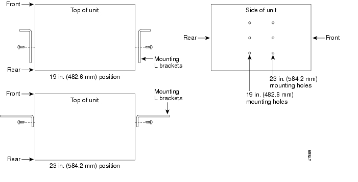
DLP-B3 Reverse the Mounting Bracket to Fit a 19-inch Rack
Caution
Caution
Step 1
Step 2
Text imprinted on the mounting bracket will now also be upside down.
Step 3
The narrow side of the mounting bracket should be towards the front of the shelf assembly. Text imprinted on the mounting bracket should be visible and upside down.
Step 4
Step 5
Step 6
Figure 1-1 Reversing the Mounting Brackets (23-Inch Position to 19-Inch Position)
Step 7
DLP-B5 Mount the ONS 15327 in a Rack
Purpose
This task allows one person to mount the shelf assembly in a rack.
Tools/Equipment
Two sets of #12-24 mounting screws
# 2 Phillips screwdriver
Fuse and alarm panel, if not installed
Prerequisite Procedures
3 Reverse the Mounting Bracket to Fit a 19-inch Rack, if applicable
Required/As Needed
As needed
Onsite/Remote
Onsite
Security Level
None
Note
Step 1
Step 2
Step 3
Step 4
Step 5
Step 6
Step 7
DLP-B7 Mount Multiple Shelf Assemblies in a Rack
Purpose
This task installs multiple shelf assemblies in a rack.
Tools/Equipment
#2 Phillips screwdriver
Medium slot-head screwdriver
Small slot-head screwdriver
Prerequisite Procedures
3 Reverse the Mounting Bracket to Fit a 19-inch Rack, if applicable
Required/As Needed
As needed
Onsite/Remote
Onsite
Security Level
None
Note
Step 1
Step 2
Note
Step 3
Step 4
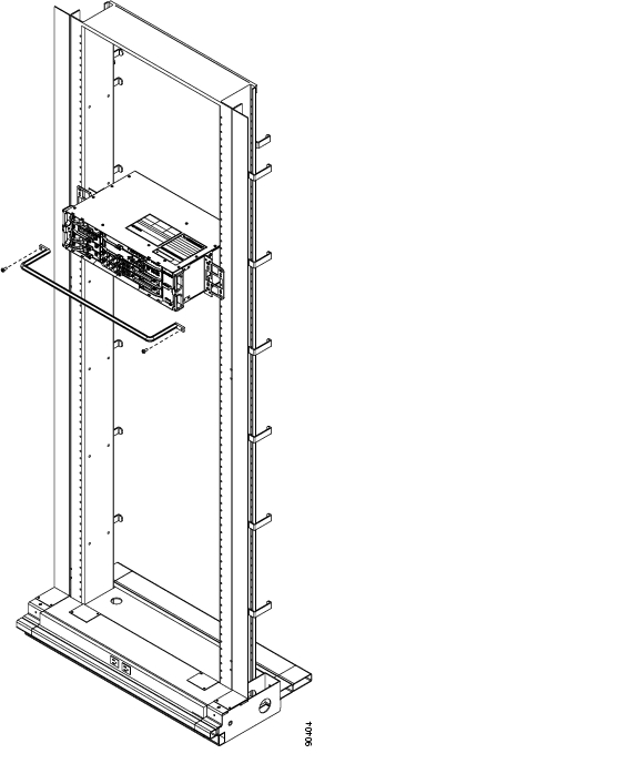
DLP-B329 Install the Tie-Down Bar
Step 1
Figure 1-2 shows the tie-down bar, the ONS 15327, and the rack.
Figure 1-2 Tie-Down Bar
Step 2
Step 3
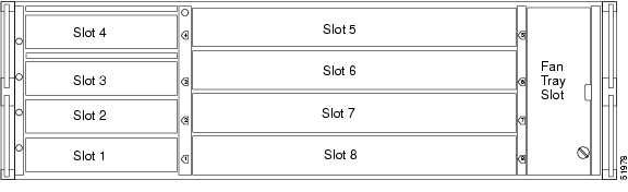
NTP-B216 Install the Mechanical Interface Cards
Warning
Step 1
a.
b.
c.
d.
The slots are keyed to ensure that cards are installed in the correct slots. Figure 1-3 shows the location and number of each slot.
Figure 1-3 ONS 15327 Slot Numbering
Step 2
Warning
Step 3
Stop. You have completed this procedure.
NTP-B6 Install the Power and Ground
Warning
Warning
Warning
Warning
Warning
Warning
Warning
Warning
Caution
Step 1
Step 2
Step 3
Step 4
Step 5
Step 6
Step 7
Stop. You have completed this procedure.
DLP-B16 Connect the Office Ground to the ONS 15327
Step 1
Step 2
Note
Step 3
Step 4
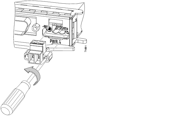
DLP-B17 Connect Office Power to the ONS 15327 Shelf (Screw-Lock Power Connector)
Warning
Caution
Note
Note
Note
Step 1
Step 2
Step 3
Warning
Step 4
Warning
Step 5
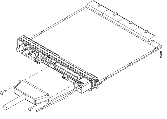
Figure 1-4 Removing the MIC Power Connector
Step 6
Step 7
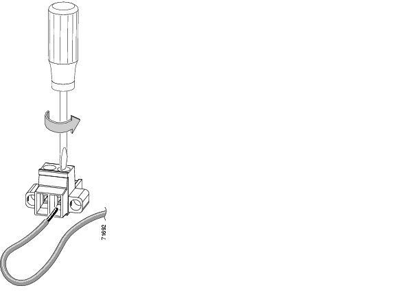
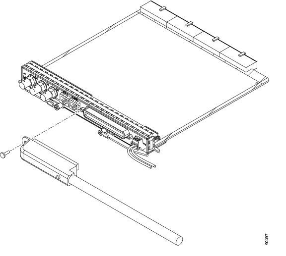
Figure 1-5 Inserting a Power Cable into the MIC Power Connector
Step 8
Step 9
Step 10
Step 11
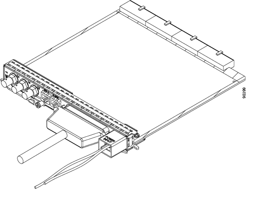
Figure 1-6 Installing the MIC Power Connector
Step 12
Step 13
Caution
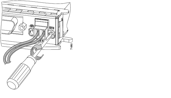
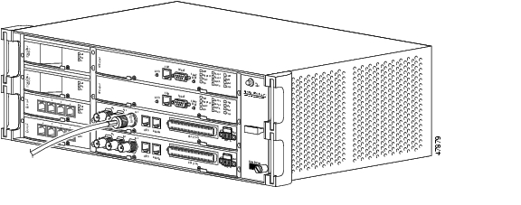
Figure 1-7 shows redundant power connected to an ONS 15327.
Figure 1-7 Redundant Power Connections
Step 14
DLP-B18 Turn On and Verify Office Power
Purpose
This task measures the power to verify correct power and returns.
Tools/Equipment
Voltmeter
Prerequisite Procedures
16 Connect the Office Ground to the ONS 15327
17 Connect Office Power to the ONS 15327 Shelf (Screw-Lock Power Connector)
Required/As Needed
Required
Onsite/Remote
Onsite
Security Level
None
Step 1
a.
Note
b.
Step 2
Step 3
a.
b.
Step 4
DLP-B30 Install Ferrites on Power Cabling
Purpose
This task installs third-party ferrites on power cables to dampen electromagnetic interference (EMI) from the ONS 15327.
Tools/Equipment
Voltmeter
Block ferrite (Fair Rite 0443164151) for each pair of cables
Prerequisite Procedures
16 Connect the Office Ground to the ONS 15327
17 Connect Office Power to the ONS 15327 Shelf (Screw-Lock Power Connector)
Required/As Needed
Required
Onsite/Remote
Onsite
Security Level
None
Note
Step 1
Step 2
Step 3
NTP-B7 Install the Fan-Tray Assembly
Caution
Caution
Caution
Step 1
Step 2
Step 3
Step 4
The FAN STATUS LED illuminates only when an XTC card is installed.
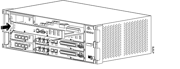
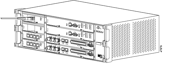
Figure 1-8 shows the location of the fan-tray assembly.
Figure 1-8 Installing the Fan-Tray Assembly
Step 5
Stop. You have completed this procedure.
NTP-B217 Install the XTCs
Purpose
This procedure installs the Cross-Connect Timing and Control (XTC) cards in Slots 5 and 6.
Tools/Equipment
None
Prerequisite Procedures
7 Install the Fan-Tray Assembly
Required/As Needed
Required
Onsite/Remote
Onsite
Security Level
Retrieve or higher
Warning
Note
Step 1
a.
b.
c.
d.
Slot 6 is the working XTC card slot.
Step 2
Note
Step 3
Step 4
Step 5
Slot 5 is the protect XTC slot.
Step 6
Step 7
Step 8
Figure 1-9 Installing an XTC (XTC 28-3)
Step 9
Stop. You have completed this procedure.
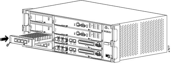
NTP-B218 Install the Optical and Ethernet Cards
Purpose
This procedure installs the optical cards (OC-3, OC-12, and OC-48) and Ethernet cards (E10/100-4, G1000-2) in Slots 1 through 4.
Tools/Equipment
None
Prerequisite Procedures
7 Install the Fan-Tray Assembly
Required/As Needed
Required
Onsite/Remote
Onsite
Security Level
Retrieve or higher
Warning
Step 1
a.
b.
c.
d.
Step 2
Step 3
Step 4
Step 5
Step 6
Figure 1-10 Installing an Ethernet Card (E10/100-T)
Step 7
Step 8
Note
Stop. You have completed this procedure.
DLP-D4 Install SFP Connectors on G1000-2 Cards
Note
Warning
Step 1
Step 2
Step 3
Step 4
Step 5
Step 6
DLP-D6 Remove SFP Connectors from G1000-2 Cards
Purpose
This task removes SFPs from your Ethernet cards.
Tools/Equipment
None
Prerequisite Procedures
Required/As Needed
As needed
Onsite/Remote
Onsite
Security Level
None
Step 1
Warning
Step 2
Step 3
Step 4
Step 5
NTP-B219 Remove and Replace a Card
Step 1
Step 2
•
•
Step 3
a.
b.
Step 4
•
Stop. You have completed this procedure.
DLP-B320 Delete a Card
Purpose
This task deletes a card from CTC.
Tools/Equipment
None
Prerequisite Procedures
Required/As Needed
As needed
Onsite/Remote
Both
Security Level
Provisioning or higher
Step 1
You cannot delete a card if any of the following conditions apply:
•
•
•
•
•
•
204 Delete a SONET DCC Termination
Note
Step 2
DLP-B247 Change an Optical Card
Caution
Step 1
a.
b.
c.
d.
e.
f.
Step 2
Step 3
Step 4
a.
b.
Step 5
NTP-B115 Preprovision a Slot
Step 1
Step 2
Step 3
Note
Step 4
Stop. You have completed this procedure.
NTP-B8 Install Wires to Alarm, Timing, LAN, and Craft Pin Connections
Step 1
Step 2
Step 3
Step 4
Step 5
Caution
Step 6
Stop. You have completed this procedure.
DLP-B321 Install External Alarm Cables
Step 1
Step 2
Step 3
Note
Step 4
Table 1-1 Alarm Input Pin Assignments
2
15
Alarm 2+
6
Alarm 2-
4
33
Alarm 1+
4
Alarm 1-
6
51
Alarm 0+
2
Alarm 0-
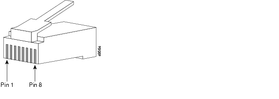
Table 1-2 Alarm (External Control) Output Pin Assignments
2
17
Contact+
8
Contact-
Figure 1-11 Pins 1 and 8 on the RJ-45 Connector
Step 5
DLP-B322 Install Timing Cables
Step 1
Step 2
Step 3
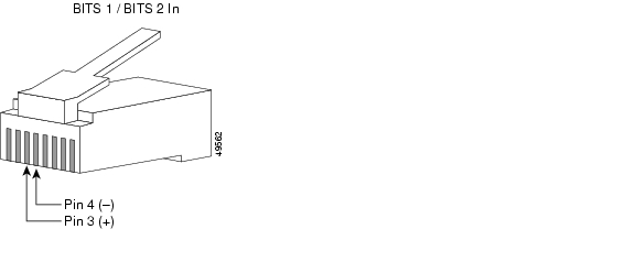
Table 1-3 BITS Cable Pin Assignments
BITS 1 In
BITS 2 In3
BITS Input+
4
BITS Input-
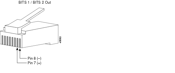
BITS 1 Out
BITS 2 Out7
BITS Output+
8
BITS Output-
Figure 1-12 BITS In Pins on the RJ-45 Connector
Figure 1-13 BITS Out Pins on the RJ-45 Connector
Note
Step 4
DLP-B323 Install the Serial Cable for TL1 Craft Interface
Purpose
This task installs the TL1 craft interface.
Tools/Equipment
Serial cable (DB-9)
Prerequisite Procedures
Required/As Needed
As needed
Onsite/Remote
Onsite
Security Level
None
Step 1
Step 2
Note
Step 3
NTP-B220 Install the Electrical Cables
Purpose
This procedure describes how to install the electrical DS-1 (AMP Champ) and DS-3 (coaxial) cables. To carry electrical traffic on the ONS 15327, you must install electrical cable.
Tools/Equipment
Shielded coaxial cable terminated with BNC connectors for DS-3 ports
Shielded ABAM cable terminated with Champ connectors for DS-1 ports with #22 or #24 AWG ground wire (typically about two feet in length)
Prerequisite Procedures
8 Install Wires to Alarm, Timing, LAN, and Craft Pin Connections
Required/As Needed
As needed
Onsite/Remote
Onsite
Security Level
None
Caution
Step 1
Step 2
Step 3
Step 4
Stop. You have completed this procedure.
DLP-B324 Install DS-1 Champ Cables on a MIC
Purpose
This task installs DS-1 cables.
Tools/Equipment
One of the following DS-1 cables (either right-angle or straight):
•
–
–
–
–
–
–
–
–
•
Installing Champ connector DS-1 cables requires 64-pin bundled cable connectors with a 64-pin male Champ connector. You need Champ connector #552285-1 for the plug side and #1-552496-1 for the right-angle shell housing, or their functional equivalents.
Prerequisite Procedures
8 Install Wires to Alarm, Timing, LAN, and Craft Pin Connections
Required/As Needed
As needed
Onsite/Remote
Onsite
Security Level
None
Caution
Step 1
Step 2
The DS-1 cable can have a straight or right-angle configuration. Figure 1-14 shows a straight DS-1 cable.
Note
Figure 1-14 Straight DS-1 Cable
Figure 1-15 shows a right-angle DS-1 cable.
Figure 1-15 Right-Angle DS-1 Cable
Step 3
Figure 1-16 Installing a Straight DS-1 Cable
Step 4
DLP-B325 Install Coaxial Cable With BNC Connectors
Caution
Step 1
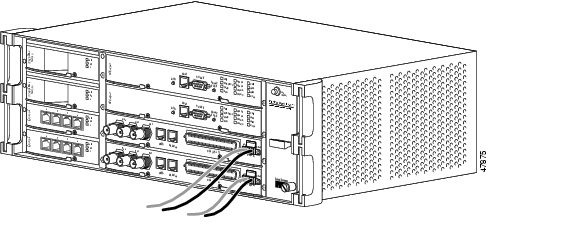
Figure 1-17 shows how to connect a coaxial cable to an ONS 15327 MIC.
Figure 1-17 Installing a Coaxial Cable with BNC Connectors
Step 2
Step 3
Step 4
Step 5
DLP-B326 Route Electrical Cables
Caution
Step 1
Step 2
Step 3
NTP-B221 Install Optical Cables
Warning
Caution
Note
Note
Note
Step 1
Step 2
Step 3
Step 4
Step 5
Figure 1-18 Installing a Fiber-Optic Cable
Step 6
Step 7
Stop. You have completed this procedure.
DLP-B327 Install Fiber-Optic Cables on the LGX Interface
Purpose
This task installs fiber-optic cables on the Lightguide Cross Connect (LGX) interface in the Central Office.
Tools/Equipment
Fiber-optic cables
Prerequisite Procedures
218 Install the Optical and Ethernet Cards
Required/As Needed
As needed
Onsite/Remote
Onsite
Security Level
None
Note
Step 1
Step 2
Step 3
Step 4
DLP-B42 Install Fiber-Optic Cables on OC-N Cards
Purpose
This task installs fiber-optic cables on optical (OC-N) cards.
Tools/Equipment
Fiber-optic cables
Prerequisite Procedures
218 Install the Optical and Ethernet Cards
NTP-B112 Clean Fiber Connectors, page 14-20
327 Install Fiber-Optic Cables on the LGX Interface (as applicable)
Required/As Needed
As needed
Onsite/Remote
Onsite
Security Level
None
Note
Note
Step 1
Step 2
Step 3
DLP-B43 Install Fiber-Optic Cables for UPSR Configurations
Purpose
This task installs the fiber-optic cables to the east and west UPSR ports at each node. See "Turn Up Network" to provision and test UPSR configurations.
Tools/Equipment
Fiber-optic cables
Prerequisite Procedures
218 Install the Optical and Ethernet Cards
Required/As Needed
As needed
Onsite/Remote
Onsite
Security Level
None
Note
Note
Note
Step 1
Step 2
Step 3
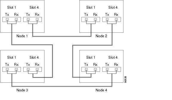
Figure 1-19 shows fiber connections for a four-node UPSR with trunk (span) cards in Slot 5 (west) and Slot 12 (east).
Figure 1-19 Connecting Fiber to a Four-Node UPSR
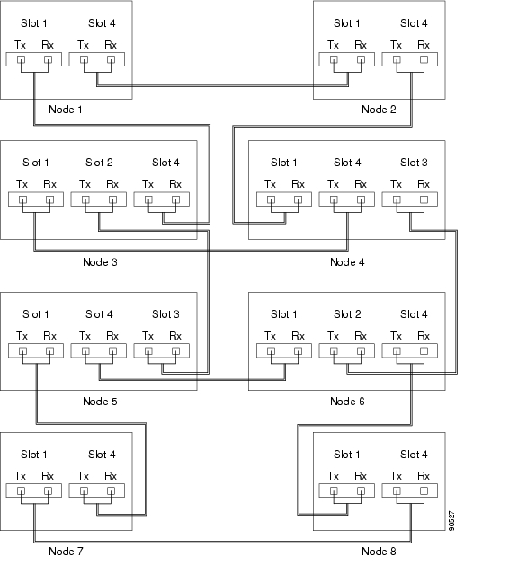
If you are creating a UPSR dual ring interconnect, Figure 1-20 shows a traditional dual ring interconnect example.
Figure 1-20 Connecting Fiber to an Eight-Node Traditional UPSR Dual-Ring Interconnect
Step 4
DLP-B44 Install Fiber-Optic Cables for BLSR Configurations
Purpose
This task installs the fiber-optics to the east and west BLSR ports at each node. See "Turn Up Network" to provision and test BLSR configurations.
Tools/Equipment
Fiber-optic cables
Prerequisite Procedures
218 Install the Optical and Ethernet Cards
Required/As Needed
As needed
Onsite/Remote
Onsite
Security Level
None
Note
Note
Note
Step 1
Step 2
Step 3
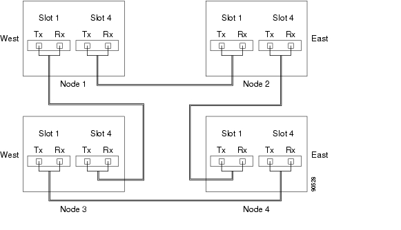
Figure 1-21 shows fiber connections for a BLSR with trunk (span) cards in Slot 5 (west) and Slot 12 (east).
Figure 1-21 Connecting Fiber to a Four-Node, Two-Fiber BLSR
Step 4
DLP-B46 Route Fiber-Optic Cables
Caution
Step 1
Step 2
Step 3
NTP-B13 Perform the Shelf Installation Acceptance Test
Step 1
Table 1-7 ONS 15327 Shelf Installation Task Summary
8 Install Wires to Alarm, Timing, LAN, and Craft Pin Connections
Step 2
Step 3
Stop. You have completed this procedure.
DLP-B33 Measure Voltage
Purpose
This task measures power so you can verify correct power and returns.
Tools/Equipment
Voltmeter
Prerequisite Procedures
6 Install the Power and Ground
Required/As Needed
Required
Onsite/Remote
Onsite
Security Level
None
Step 1
a.
Step b.b.
Step 2
a.
•
•
•
b.
Step 3
![]()
![]()
![]()
![]()
![]()
![]()
![]()
![]()
Posted: Mon Feb 25 06:11:52 PST 2008
All contents are Copyright © 1992--2008 Cisco Systems, Inc. All rights reserved.
Important Notices and Privacy Statement.