|
|

Table Of Contents
Alternate Installation Procedures
NTP-B223 Install the Fiber-Optic Cable Storage Drawer
NTP-B224 Route Cables Through the Fiber-Optic Cable Storage Drawer
NTP-B222 Connect Office Power to the ONS 15327 Shelf (Terminal-Lug Power Connector)
Alternate Installation Procedures
This appendix describes installation procedures that can be used in place of some of the procedures contained in Chapter 1, "Install Hardware."
Before You Begin
This section lists the chapter procedures (NTPs). Turn to a procedure for applicable tasks (DLPs).
1.
223 Install the Fiber-Optic Cable Storage Drawer—As needed, complete this procedure to install the cable storage drawer that you can use to store slack cable.
2.
3.
Warning
Warning
Warning
Note
Note
NTP-B223 Install the Fiber-Optic Cable Storage Drawer
Note
Step 1
Note
Step 2
Step 3
NTP-B224 Route Cables Through the Fiber-Optic Cable Storage Drawer
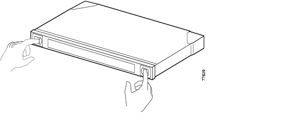
Step 1
Figure D-1 Opening the Fiber-Optic Cable Storage Drawer
Step 2
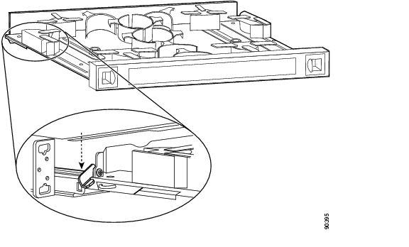
Step 3
Figure D-2 Locking the Cable Storage Drawer
Step 4
Step 5
Step 6
Step 7
Step 8
Step 9
Step 10
NTP-B222 Connect Office Power to the ONS 15327 Shelf (Terminal-Lug Power Connector)
Purpose
This procedure connects power to the ONS 15327 shelf.
Tools/Equipment
#2 Phillips screwdriver
Medium slot head screwdriver
Small slot head screwdriver
Wire wrapper
Wire cutters
Wire strippers
Crimp tool
Fuse panel
Terminal-lug power connectors (2)
Terminal lugs (4)
Terminal lug screws (4)
Power cable (from fuse and alarm panel to assembly), #10 AWG, copper conductors, 194ΑF [90ΑC])
Ground cable #6 AWG stranded
Listed pressure terminal connectors such as ring and fork types; connectors must be suitable for #10 AWG copper conductors
Labels (2) (one for the A-side power lead and one for the B-side)
Prerequisite Procedures
DLP-B16 Connect the Office Ground to the ONS 15327, page 1-13
Required/As Needed
Required
Onsite/Remote
Onsite
Security Level
None
Note
Note
Warning
Step 1
Step 2
Step 3
Warning
Step 4
Warning
Caution
Note
Step 5
Step 6
Step 7
Step 8
Warning
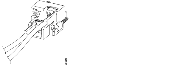
Figure D-3 MIC Terminal-Lug Power Connector
Step 9
Step 10
Warning
Step 11
Step 12
Step 13
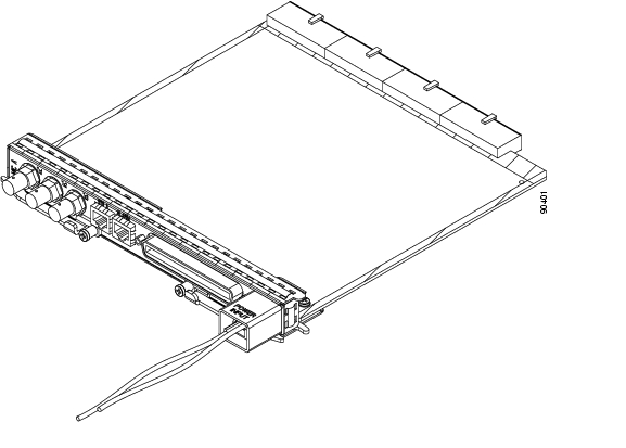
Figure D-4 shows power cables connected to the terminal-lug power connector on the MIC.
Figure D-4 Power Cable Inserted into the MIC Terminal-Lug Power Connector
Step 14
Step 15
Caution
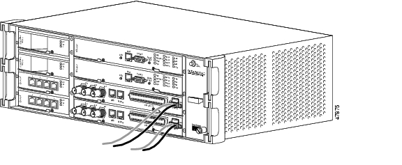
Figure D-5 shows redundant power connected to an ONS 15327.
Figure D-5 Redundant Power Connected to an ONS 15327
Stop. You have completed this procedure.
![]()
![]()
![]()
![]()
![]()
![]()
![]()
![]()
Posted: Mon Feb 25 06:05:04 PST 2008
All contents are Copyright © 1992--2008 Cisco Systems, Inc. All rights reserved.
Important Notices and Privacy Statement.