|
|

Table Of Contents
NTP-B195 Document Existing Provisioning
NTP-B196 View Alarms, History, Events, and Conditions
DLP-B111 Changing the Maximum Number of Session Entries for Alarm History
DLP-B112 Display Alarms and Conditions Using Time Zone
NTP-B68 Delete Cleared Alarms from Display
NTP-B69 View Alarm-Affected Circuits
NTP-B70 Create, Download, and Assign Alarm Severity Profiles
DLP-B115 Create Alarm Severity Profiles
DLP-B223 Download an Alarm Severity Profile
DLP-B116 Apply Alarm Profiles to Ports
DLP-B117 Apply Alarm Profiles to Cards and Nodes
DLP-B118 Delete Alarm Severity Profiles
NTP-B168 Enable, Modify, or Disable Alarm Severity Filtering
DLP-B225 Enable Alarm Filtering
DLP-B226 Modify Alarm and Condition Filtering Parameters
DLP-B227 Disable Alarm Filtering
NTP-B72 Suppress and Discontinue Alarm Suppression
DLP-B119 Suppress Alarm Reporting
DLP-B120 Discontinue Alarm Suppression
NTP-B32 Provision External Alarms and Controls on the XTC
Manage Alarms
This chapter explains how to view and manage the alarms and conditions on a Cisco ONS 15327.
Cisco Transport Controller (CTC) detects and reports SONET alarms generated by the Cisco ONS 15327 and the larger SONET network. You can use CTC to monitor and manage alarms at a card, node, or network level. You can also view alarm counts on the LCD front panel.
Before You Begin
This section lists the chapter procedures (NTPs). Turn to a procedure for applicable tasks (DLPs).
1.
195 Document Existing Provisioning—Complete this procedure as needed to record node information or to troubleshoot rings and spans.
2.
3.
4.
5.
6.
7.
NTP-B195 Document Existing Provisioning
Step 1
Step 2
Step 3
Stop. You have completed this procedure.
DLP-B138 Print CTC Data
Step 1
The print operation is available for all network, node (default login), and card view windows.
Step 2
Step 3
•
•
•
•
•
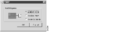
The Table Contents option prints all the data contained in a table with the same column headings. For example, if you print the History window Table Contents view, you print all data included in the table whether or not items appear in the window.
Tip
Figure 6-1 Selecting CTC Data For Print
Step 4
Step 5
Step 6
Step 7
DLP-B139 Export CTC Data
Step 1
Step 2
Step 3
•
•
•
Step 4
Text editor and word processor applications display the data exactly as it is exported, including comma or tab separators. All applications that open the data files allow you to format the data.
Step 5
Spreadsheet and database management programs also allow you to manage the exported data.
Note
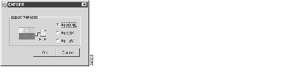
The export operation only applies to tabular data, so it is not available for the following CTC tabs and subtabs:
•
•
Figure 6-2 Selecting CTC Data For Export
Step 6
Step 7
•
•
•
Step 8
Step 9
Step 10
Step 11
NTP-B196 View Alarms, History, Events, and Conditions
Step 1
Step 2
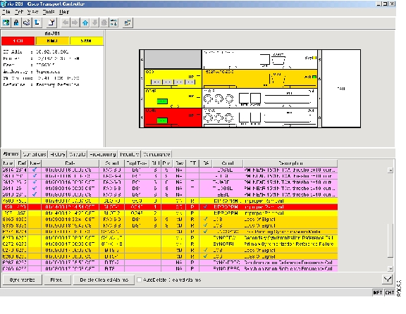
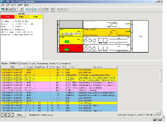
Figure 6-3 ONS 15327 CTC Node (Login) View
Table 6-1 lists the columns in the Alarms window and their descriptions.
Table 6-2 lists the color codes for alarm and condition severities.
Step 3
Step 4
Stop. You have completed this procedure.
DLP-B110 View Alarm History
Step 1
Step 2
a.
b.
Tip
Step 3
Step 4
Alarms and conditions (events) raised during the current session appear.
Step 5
The previous view is the node (default login) view.
Step 6
Note
a.
b.
Note
Step 7
History > Card window.Step 8
Step 9
Tip
Step 10
DLP-B111 Changing the Maximum Number of Session Entries for Alarm History
Step 1
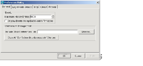
The CTC Preferences Dialog box appears ( Figure 6-4).
Figure 6-4 CTC Preferences Dialog Box
Step 2
Step 3
Note
Note
Step 4
DLP-B112 Display Alarms and Conditions Using Time Zone
Step 1
The CTC Preferences Dialog box appears ( Figure 6-4).
Step 2
Step 3
Step 4
DLP-B113 Synchronize Alarms
Step 1
Step 2
This button causes CTC to retrieve a current alarm summary for the card, node, or network. This step is optional because CTC updates the Alarms window automatically as messages arrive from the node.
Alarms that have been raised during the session will have a check mark in the Alarms window New column. When you click Synchronize, the check mark disappears.
Step 3
DLP-B114 View Conditions
Step 1
Step 2
The Retrieve button requests the current set of fault conditions from the node, card, or network. The window is not updated when conditions change on the node. You must click Retrieve to see any changes.
Figure 6-5 Node View Conditions Window
Conditions include all fault conditions raised on the node, whether or not they are reported.
Note
Events that are reported as Major (MJ), Minor (MN), or Critical (CR) severities are alarms. Events that are reported as Not-Alarmed (NA) are conditions. Conditions that are not reported at all are marked Not-Reported (NR) in the Conditions window severity column.
Conditions that have a default severity of Critical (CR), Major (MJ), Minor (MN), or Not-Alarmed (NA) but are not reported due to exclusion or suppression are shown as NR in the Conditions window.
Note
Current conditions are shown with the severity chosen in the alarm profile, if used. (For more information about alarm profiles, see the "70 Create, Download, and Assign Alarm Severity Profiles" section.)
Note
Step 3
An exclusion rule eliminates all lower-level alarms or conditions that originate from the same cause. For example, a fiber break may cause an LOS alarm, an AIS condition, and an SF condition. If you check the Exclude Same Root Cause checkbox, only the LOS alarm will appear. According to Telcordia, exclusion rules apply to a query of "all conditions from a node."
Step 4
NTP-B68 Delete Cleared Alarms from Display
Step 1
Step 2
a.
b.
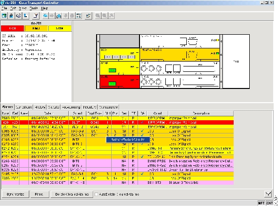
This action removes any cleared ONS 15327 alarms from the Alarms display. The rows of cleared alarms turn white and have a C in their status (ST) column ( Figure 6-5).
Step 3
Step 4
a.
b.
Step 8.Step 5
Step 6
a.
b.
Step 7
Step 8
•
•
Step 9
Stop. You have completed this procedure.
NTP-B69 View Alarm-Affected Circuits
Step 1
Step 2
Note
Note
The Select Affected Circuit option appears on the shortcut menu ( Figure 6-6).
Figure 6-6 Select Affected Circuits Option
Step 3
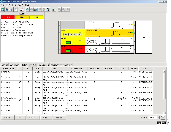
The Circuits window appears with the affected circuits highlighted ( Figure 6-7).
Figure 6-7 Viewing an Alarm-Affected Circuit
Step 4
Stop. You have completed this procedure.
NTP-B70 Create, Download, and Assign Alarm Severity Profiles
Step 1
Step 2
Step 3
Step 4
Stop. You have completed this procedure.
DLP-B115 Create Alarm Severity Profiles
Step 1
Step 2
Step 3
Step 4
Step 5
Step 6
Step 7
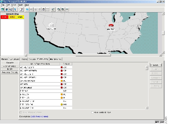
The default alarm severity profile appears in the Alarm Profiles window ( Figure 6-8).
Figure 6-8 Network View Alarm Profiles Window
Step 8
Step 9
Tip
Step 10
Profile names must be unique. If you try to import or name a profile that has the same name as another profile, CTC adds a suffix to create a new name. Long file names are supported (45 character maximum).
Step 11
A new alarm profile (named in Step 10) is created. This profile duplicates the default profile severities and appears to the right of the default profile in the Alarm Profiles window. You can highlight it and drag it to a different position.
Step 12
a.
b.
c.
Step 13
Step 14
Step 15
a.
•
•
•
•
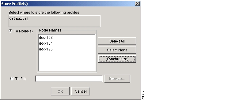
b.
c.
Long file names are supported. CTC supplies a suffix of *.pfl.
d.
Note
Note
Figure 6-9 Store Profile(s) Dialog Box
Step 16
DLP-B223 Download an Alarm Severity Profile
Step 1
Step 2
Step 3
Step 4
a.
The Open dialog box appears.
b.
c.
The file must have the *.pfl extension.
d.
Continue with Step 6.
Step 5
a.
b.
Step 6
The downloaded profile appears at the right side of the Alarm Profiles window.
Step 7
Step 8
Step 9
a.
•
•
•
•
b.
Step 10
DLP-B116 Apply Alarm Profiles to Ports
Purpose
Use this task to apply a custom or default alarm severity profile to a port or ports.
Tools/Equipment
None
Prerequisite Procedures
115 Create Alarm Severity Profiles
Required/As Needed
As needed
Onsite/Remote
Onsite or remote
Security Level
Provisioning or higher
Step 1
Step 2
Note
Note
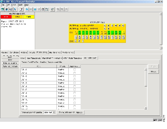
Step 3
Figure 6-10 shows an alarm profile for OC-3 card ports. CTC shows Parent Card Profile: Inherited.
Figure 6-10 Card View Optical Port Alarm Profile
Step 4
a.
b.
c.
Step 5
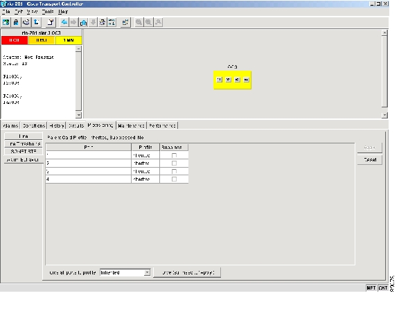
Step 6
Figure 6-11 Card View Electrical Port Alarm Profile
Step 7
Step 8
a.
b.
c.
Tip
Step 9
DLP-B117 Apply Alarm Profiles to Cards and Nodes
Purpose
Use this task to apply a custom or default alarm profile to cards or nodes.
Tools/Equipment
None
Prerequisite Procedures
115 Create Alarm Severity Profiles
Required/As Needed
As needed
Onsite/Remote
Onsite or remote
Security Level
Provisioning or higher
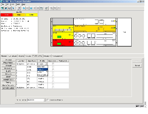
Step 1
Figure 6-12 Node View Alarm Profile
Step 2
a.
b.
c.
Continue with Step 4.
Step 3
a.
b.
c.
Tip
Step 4
DLP-B118 Delete Alarm Severity Profiles
Step 1
Step 2
Step 3
The selected alarm profile name is displayed in the Description field.
Step 4
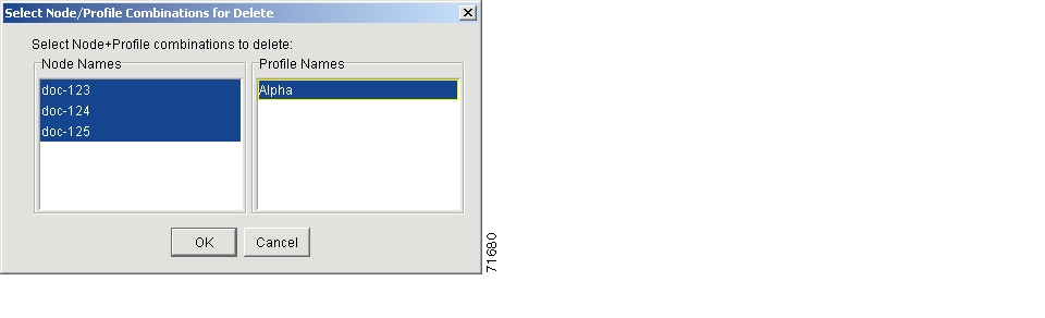
The Select Node/Profile Combination for Delete dialog box appears ( Figure 6-13).
Figure 6-13 Select Node/Profile Combination For Delete Dialog Box
Step 5
Tip
Step 6
Step 7
The Delete Alarm Profile confirmation dialog box appears.
Step 8
Note
Provisioning > Alarm Profiles window unless you remove it by choosing Remove.Step 9
Note
Note
Step 10
NTP-B168 Enable, Modify, or Disable Alarm Severity Filtering
Step 1
Step 2
Step 3
Step 4
Stop. You have completed this procedure.
DLP-B225 Enable Alarm Filtering
Step 1
Step 2
Alarm filtering is enabled if the tool is selected and disabled if the tool is raised (not selected).
Alarm filtering will be enabled in the card, node, and network views of the Alarms tab at the node and for all other nodes in the network. If, for example, the Alarm Filter tool is enabled in the Alarms tab of the node view at one node, the Alarms tab in the network view and card view of that node will also show the tool enabled. All other nodes in the network will also have the tool enabled.
If you filter an alarm in card view, the alarm will still be displayed in node view. In this view, the card will display the color of the highest-level alarm. The alarm is also shown for the node in the network view.
Step 3
Step 4
Step 5
DLP-B226 Modify Alarm and Condition Filtering Parameters
Step 1
Step 2
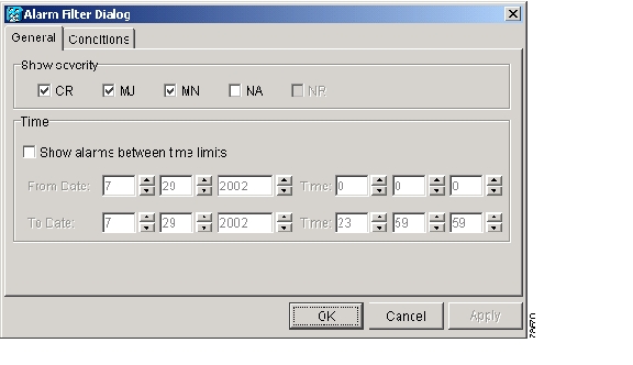
The Alarm Filter Dialog box appears, showing the General tab ( Figure 6-14).
Figure 6-14 Alarm Filter Dialog Box General Tab
In the General tab Show Severity area, you can choose which alarm severities will show through the alarm filter and provision a snapshot period during which alarms will appear. To change the alarm severities shown in the filter, continue with Step 3. To change the alarm time period, continue with Step 4.
Step 3
Note
Step 4
To modify filter parameters for conditions, continue with Step 5. If you do not need to modify them, continue with Step 6.
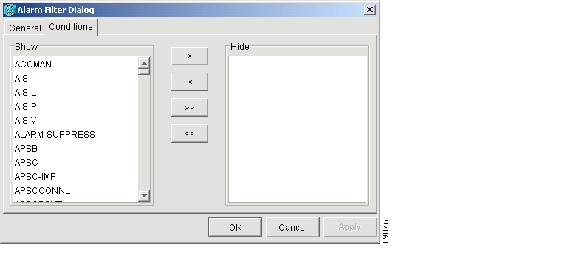
Step 5
Figure 6-15 Alarm Filter Dialog Box Conditions Tab
When alarm filtering is enabled, conditions in the Show list are visible and conditions in the Hide list are invisible.
•
•
•
•
Note
Step 6
Alarm and condition filtering parameters are enforced when alarm filtering is enabled (see the "DLP-B225 Enable Alarm Filtering" task), and are not enforced when alarm filtering is disabled (see the "DLP-B227 Disable Alarm Filtering" task).
Step 7
DLP-B227 Disable Alarm Filtering
Step 1
Step 2
Alarm filtering is enabled if the tool is selected and disabled if the tool is raised (not selected).
Step 3
Step 2.Step 4
Step 2.Step 5
NTP-B72 Suppress and Discontinue Alarm Suppression
Step 1
Step 2
Note
Step 3
Stop. You have completed this procedure.
DLP-B119 Suppress Alarm Reporting
Caution
Step 1
Step 2
Step 3
Note
Step 4
The node sends out autonomous messages to clear any raised alarms.
Step 5
Provisioning > Alarm Behavior tabs.Step 6
Step 7
Step 8
Step 9
Step 10
Step 11
DLP-B120 Discontinue Alarm Suppression
Step 1
Note
Step 2
Step 3
Step 4
Step 5
Step 6
Step 7
Step 8
Step 9
Step 10
NTP-B32 Provision External Alarms and Controls on the XTC
Note
Note
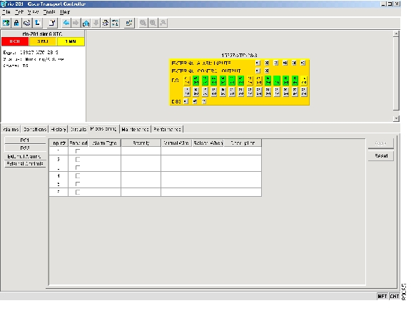
Step 1
Step 2
Note
Figure 6-16 XTC Card External Alarms
Step 3
•
•
•
The severity determines the severity the alarm has in the Alarms and History tabs and determines whether the LEDs are activated. Critical (CR), Major (MJ), and Minor (MN) alarms activate the XTC LEDs. Not-Alarmed (NA) and Not-Reported (NR) do not activate LEDs, but do report the information in CTC.
•
•
•
Step 4
Step 5
Step 6
Step 7
•
•
•
•
Step 8
Step 9
Stop. You have completed this procedure.
![]()
![]()
![]()
![]()
![]()
![]()
![]()
![]()
Posted: Mon Feb 25 06:21:32 PST 2008
All contents are Copyright © 1992--2008 Cisco Systems, Inc. All rights reserved.
Important Notices and Privacy Statement.