cc/td/doc/product/ong/15327/r34userd
hometocprevnextglossaryfeedbacksearchhelp
PDF

Table Of Contents

Turn Up Network

Before You Begin

NTP-B35 Verify Node Turn Up

NTP-B124 Provision a Point-to-Point Network

DLP-B253 Provision SONET DCC Terminations

DLP-B214 Change the Service State for a Port

NTP-B173 Point-to-Point Network Acceptance Test

DLP-B254 XTC Active/Standby Switch Test

DLP-B88 Optical 1+1 Protection Test

NTP-B38 Provision a Linear ADM Network

NTP-B174 Linear ADM Network Acceptance Test

NTP-B40 Provision BLSR Nodes

NTP-B126 Create a BLSR

NTP-B175 BLSR Acceptance Test

DLP-B217 BLSR Exercise Ring Test

DLP-B91 BLSR Ring Switch Test

NTP-B44 Provision UPSR Nodes

NTP-B177 UPSR Acceptance Test

DLP-B94 UPSR Protection Switching Test

NTP-B46 Subtend a UPSR from a BLSR

NTP-B47 Subtend a BLSR from a UPSR

NTP-B48 Subtend a BLSR from a BLSR


Turn Up Network


This chapter explains how to turn up and test a Cisco ONS 15327 network, including terminal point-to-point networks, linear add-drop multiplexers (ADMs), unidirectional path switched rings (UPSRs), bidirectional line switched rings (BLSRs) and subtending rings.

Before You Begin

This section lists the chapter procedures (NTPs). Turn to a procedure for applicable tasks (DLPs).

1. 35 Verify Node Turn Up—Complete this procedure before beginning network turn up.

2. 124 Provision a Point-to-Point Network—Complete as needed.

3. 173 Point-to-Point Network Acceptance Test—Complete this procedure after you provision a point-to-point network.

4. 38 Provision a Linear ADM Network—Complete as needed.

5. 174 Linear ADM Network Acceptance Test—Complete this procedure after you provision a linear ADM.

6. 40 Provision BLSR Nodes—Complete this procedure to provision ONS 15327s in a two-fiber BLSR.

7. 126 Create a BLSR—Complete this procedure after provisioning the BLSR nodes.

8. 175 BLSR Acceptance Test—Complete this procedure after you provision a two-fiber BLSR.

9. 44 Provision UPSR Nodes—Complete as needed.

10. 177 UPSR Acceptance Test—Complete this procedure after you provision a UPSR.

11. 46 Subtend a UPSR from a BLSR—Complete as needed.

12. 47 Subtend a BLSR from a UPSR—Complete as needed.

13. 48 Subtend a BLSR from a BLSR—Complete as needed.

NTP-B35 Verify Node Turn Up

Purpose

This procedure verifies that each ONS 15327 is ready for network
turn up before adding nodes to a network.

Tools/Equipment

None

Prerequisite Procedures

"Turn Up Node"

Required/As Needed

Required

Onsite/Remote

Onsite

Security Level

Provisioning or higher


Step 1 Complete the "DLP-B60 Log into CTC" task at any node on the network you will test. If you are already logged in, proceed to Step 2.

Step 2 Click the Alarms tab.

a. Verify that the network does not have any unexplained alarms. If alarms are present, investigate and resolve them before continuing. Refer to the Cisco ONS 15327 Troubleshooting Guide for procedures.

b. Ensure that the alarm filter icon in the lower right corner is not indented. If so, click it once to turn it off. When you are done checking for alarms, click the icon again to turn alarm filtering back on. See the "DLP-B227 Disable Alarm Filtering" task for instructions.

Step 3 Verify that the SW Version and Defaults displayed in the node view status area match the software version and network element (NE) defaults shown in your site plan. If any values are not correct, complete the following procedures as needed:

If the software is not the correct version, install the correct version from the ONS 15327 software CD. Upgrade procedures are located on the CD. Follow the upgrade procedures appropriate to the software currently installed on the node.

If the node defaults are not correct, complete the "165 Import Network Element Defaults" procedure.

Step 4 Click the Provisioning > General tabs. Verify that all general node information settings match the settings of your site plan. If not, see the "81 Change Node Management Information" procedure.

Step 5 Click the Provisioning > Timing tabs. Verify that the timing settings match the settings on your site plan. If not, see the "85 Change Node Timing" procedure.

Step 6 Click the Provisioning > Network tabs. Ensure that the IP settings and other CTC network access information is correct. If not, see the "201 Change CTC Network Access" procedure.

Step 7 Click the Provisioning > Protection tabs. Verify that all protection groups have been created according to your site plan. If not, see the "203 Modify or Delete 1+1 Card Protection Settings" procedure.

Step 8 Click the Provisioning > Security tabs. Verify that all users have been created and their security levels match the settings indicated by your site plan. If not, see the "205 Modify Users and Change Security" procedure.

Step 9 If SNMP is provisioned on the node, click the Provisioning > SNMP tabs. Verify that all SNMP settings match the settings of your site plan. If not, see the "87 Change SNMP Settings" procedure.

Stop. You have completed this procedure.


NTP-B124 Provision a Point-to-Point Network

Purpose

This procedure provisions two ONS 15327s in a point-to-point (terminal) network.

Tools/Equipment

None

Prerequisite Procedures

35 Verify Node Turn Up

Required/As Needed

Required

Onsite/Remote

Onsite

Security Level

Provisioning or higher


Step 1 Log into an ONS 15327 on the network where you want to provision a point-to-point configuration. See the "DLP-B60 Log into CTC" task for instructions. If you are already logged in, continue with Step 2.

Step 2 Click the Provisioning > Protection tabs. Verify that 1+1 protection is created for the OC-N cards. Complete the "170 Create Optical Protection Groups" procedure if protection has not been created.

Step 3 Repeat Steps 1 and 2 for the second point-to-point node.

Step 4 Verify that the working and protect cards in the 1+1 protection groups correspond to the physical fiber connections between the nodes, that is, verify that the working card in one node connects to the working card in the other node and that the protect card in one node connects to the protect card in the other node.

Step 5 Complete the "DLP-B253 Provision SONET DCC Terminations" task for the working OC-N port on both point-to-point nodes.


Note DCC terminations are not provisioned on the protect ports.


Note If the point-to-point nodes are not connected to a LAN, you will need to create the DCC terminations using a craft (direct) connection to the node. Remote provisioning is possible only after all nodes in the network have DCC terminations provisioned to in-service OC-N ports.


Step 6 Verify that timing is set up at both point-to-point nodes. If not, complete the "28 Set Up Timing" procedure for one or both of the nodes. If a node uses line timing, make its working OC-N the timing source.

Step 7 Complete the "173 Point-to-Point Network Acceptance Test" procedure.

Stop. You have completed this procedure.


DLP-B253 Provision SONET DCC Terminations

Purpose

This task creates the SONET Data Communications Channel terminations required for alarms, administration, data, signal control information, and messages.

Tools/Equipment

None

Prerequisite Procedures

60 Log into CTC

Required/As Needed

As needed

Onsite/Remote

Onsite or remote

Security Level

Provisioning or higher


Step 1 In node view click the Provisioning > SONET DCC tabs.

Step 2 Click Create.

Step 3 In the Create SDCC Terminations dialog box click the ports where you want to create the DCC termination. To select more than one port, press the Shift key or the Ctrl key.


Note SDCC refers to the Section DCC, which is used for ONS 15327 DCC terminations. The SONET Line DCCs and the Section DCC (when not used as a DCC termination by the ONS 15327) can be provisioned as DCC tunnels. See the "DLP-B313 Create a DCC Tunnel" task.


Step 4 Under Port State, click the Set to IS radio button.

Step 5 Verify that the Disable OSPF on DCC Link check box is unchecked.

Step 6 Click OK.


Note EOC (DCC Termination Failure) and LOS (Loss of Signal) alarms are present until you create all network DCC terminations and put the DCC termination OC-N ports in service.


Note There are four possibilities for the appearance of DCCs: green/solid, green/dashed, gray/solid, gray/dashed. DCC appearance corresponds to the following states: active/routable, active/nonroutable, failed/routable, or failed/nonroutable. Circuit provisioning uses active/routable links. Selecting a node or span in the graphic area displays information about the node and span in the status area.


Step 7 Return to your originating procedure (NTP).


DLP-B214 Change the Service State for a Port

Purpose

This task places a port in service or removes a port from service.

Tools/Equipment

None

Prerequisite Procedures

60 Log into CTC

Required/As Needed

As needed

Onsite/Remote

Onsite or remote

Security Level

Provisioning or higher


Note To provision Ethernet ports, see the "DLP-B220 Provision E-Series Ethernet Ports" task or the "DLP-B222 Provision G-Series Ethernet Ports" task.


Step 1 On the node view shelf graphic, double-click the card with the port(s) you want to put in or out of service. The card view appears.

Step 2 Click the Provisioning > Line tabs.

Step 3 Under State, choose one of the following:

IS—The port is in-service.

OOS—The port is out-of-service. Traffic is not passed on the port until the service state is changed to IS, OOS_MT, or OOS_AINS.

OOS_MT—The port is in a maintenance state. The maintenance state does not interrupt traffic flow, alarm reporting is suppressed, and loopbacks are allowed. Raised fault conditions, whether their alarms are reported or not, can be retrieved on the CTC Conditions tab or by using the TL1 RTRV-COND command. Use OOS_MT for testing or to suppress alarms temporarily. Change the state to IS, OOS, or OOS_AINS when testing is complete.

OOS_AINS—The port is in an auto-inservice state; alarm reporting is suppressed, but traffic is carried and loopbacks are allowed. Raised fault conditions, whether their alarms are reported or not, can be retrieved on the CTC Conditions tab or by using the TL1 RTRV-COND command.

Step 4 If you change the state to OOS-AINS, set the soak period time in the AINS Soak field. This is the amount of time that the state will stay in OOS-AINS state after the signal is continuously received before changing to IS.


Note A continuously valid signal must be received for the duration of the soak period before the state makes a transition to the IS state. For example, if the soak timer is set for eight hours, and you receive an error after two hours, the timer is reset for another eight-hour period. This cycle continues until an error-free signal is received for an eight-hour period.


Step 5 Click Apply.

Step 6 As needed, repeat this task for each port.

Step 7 Return to your originating procedure (NTP).


NTP-B173 Point-to-Point Network Acceptance Test

Purpose

This procedure tests a point-to-point network.

Tools/Equipment

Test set/cables appropriate to the test circuit you will create

Prerequisite Procedures

124 Provision a Point-to-Point Network

Required/As Needed

As needed

Onsite/Remote

Onsite

Security Level

Provisioning or higher


Step 1 Log into one of the point-to-point nodes. See the "DLP-B60 Log into CTC" task for instructions. If you are already logged in, continue with Step 2.

Step 2 From the View menu choose Go to Network View.

Step 3 Click the Alarms tab.

a. Verify that the network does not have any unexplained alarms. If unexplained alarms are present, resolve them before continuing. Refer to the Cisco ONS 15327 Troubleshooting Guide.

b. Ensure that the alarm filter icon in the lower right corner is not indented. If so, click it once to turn it off. When you are done checking for alarms, click the icon again to turn alarm filtering back on. See the "DLP-B227 Disable Alarm Filtering" task for instructions.

Step 4 Complete the "DLP-B139 Export CTC Data" task to export the alarm data to a file.

Step 5 Click the Conditions tab. Verify that the network does not have any unexplained conditions. If unexplained conditions are present, resolve them before continuing. Refer to the Cisco ONS 15327 Troubleshooting Guide.

Step 6 Complete the "DLP-B139 Export CTC Data" task to export the condition data to a file.

Step 7 On the network map, double-click one point-to-point node to display it in node view.

Step 8 Create a test circuit from the login node to the other point-to-point node:

For DS-1 circuits, complete the "181 Create an Automatically Routed DS-1 Circuit" procedure. When you set the circuit state, choose IS and check the Apply to drop ports check box.

For DS-3 circuits, complete the "184 Create an Automatically Routed DS-3 Circuit" procedure. When you set the circuit state, choose IS and check the Apply to drop ports check box.

Step 9 Configure the test set for the test circuit type you created:

DS-1—If you are testing an unmuxed DS-1, you must have a DSX-1 panel or a direct DS-1 interface into the ONS 15327 through the AMP Champ connectors on the Mechanical Interface Card (MIC). Set the test set for DS-1. For information about configuring your test set, consult your test set user guide.

DS-3—If you are testing a clear channel DS-3, you must have a DSX-3 panel or a direct DS-3 interface into the ONS 15327 through the BNC connectors on the MIC. Set the test set for clear channel DS-3. For information about configuring your test set, consult your test set user guide.

Step 10 Verify the integrity of all patch cables that will be used in this test by connecting one end to the test set transmit (Tx) connector and the other end to the test set receive (Rx) connector. If the test set does not run error-free, check the cable for damage and check the test set to make sure it is set up correctly before going to Step 11.

Step 11 Create a physical loopback at the circuit destination card. To do so, attach one end of a patch cable to the destination port transmit (Tx) connector; attach the other end to the port receive (Rx) connector.

Step 12 At the circuit source card:

a. Connect the transmit (Tx) connector of the test set to the receive (Rx) connector on the circuit source card.

b. Connect the test set receive (Rx) connector to the circuit transmit (Tx) connector on the circuit source card.

Step 13 Verify that the test set displays a clean signal. If a clean signal is not displayed, repeat Steps 8 to 12 to make sure the test set and cabling are configured correctly.

Step 14 Inject BIT errors from the test set. Verify that the errors display at the test set, indicating a complete end-to-end circuit.

Step 15 Complete the "DLP-B254 XTC Active/Standby Switch Test" task.

Step 16 Complete the "DLP-B88 Optical 1+1 Protection Test" task.

Step 17 Set up and complete a BER test. Use the existing configuration and follow your site requirements for the specified length of time. Record the test results and configuration.

Step 18 Remove any loopbacks, switches, or test sets from the nodes after all testing is complete. Refer to the Cisco ONS 15327 Troubleshooting Guide.

Step 19 From the View menu choose Go to Network View.

Step 20 Click the Alarms tab. Verify that the network does not have any unexplained alarms. If unexplained alarms are present, resolve them before continuing. Refer to the Cisco ONS 15327 Troubleshooting Guide.

Step 21 Repeat Steps 11 to 20 for the other point-to-point node.

Step 22 If a node fails any test, repeat the test while verifying correct setup and configuration. If the test fails again, refer to the next level of support.

Step 23 Delete the test circuit. See the "152 Delete Circuits" procedure for instructions.

After all tests are successfully completed and no alarms exist in the network, the network is ready for service application.

Stop. You have completed this procedure.


DLP-B254 XTC Active/Standby Switch Test

Purpose

This task verifies that the ONS 15327 XTC cards can effectively switch from one to another.

Tools/Equipment

The test set specified by the acceptance test procedure, connected and configured as specified in the acceptance test procedure.

Prerequisite Procedures

60 Log into CTC

Required/As Needed

Required

Onsite/Remote

Onsite

Security Level

Provisioning or higher


Step 1 From the View menu choose Go to Network View.

Step 2 Click the Alarms tab.

a. Verify that the network does not have any unexplained alarms. If unexplained alarms are present, resolve them before continuing. Refer to the Cisco ONS 15327 Troubleshooting Guide.

b. Ensure that the alarm filter icon in the lower right corner is not indented. If so, click it once to turn it off. When you are done checking for alarms, click the icon again to turn alarm filtering back on. See the "DLP-B227 Disable Alarm Filtering" task for instructions.

Step 3 Click the Conditions tab. Verify that the network does not have any unexplained conditions. If unexplained conditions are present, resolve them before continuing. Refer to the Cisco ONS 15327 Troubleshooting Guide.

Step 4 Display the node containing the XTC cards you are testing in node view.

Step 5 Make a note of which XTC is active and which is standby by examining the LEDs on the shelf graphic. XTC cards are installed in Slot 5 and Slot 6. The active XTC has a green ACT LED, and the standby XTC has an amber SBY LED.

Step 6 On the shelf graphic, right-click the active XTC and choose Reset from the shortcut menu.

Step 7 On the Resetting Card dialog box, click Yes. After 20 to 40 seconds, a "lost node connection, changing to network view" message appears.

Step 8 Click OK. On the network view map, the node where you reset the XTC will be grey.

Step 9 After the node icon turns green (within 1-2 minutes), double-click it. On the shelf graphic, observe the following:

The previous standby XTC displays a green ACT LED.

The previous active XTC LEDs go through the following LED sequence: NP (card not present), Ldg (software is loading), amber SBY LED (XTC is in standby mode). The LEDs should complete this sequence within 5 to 10 minutes.

Step 10 Verify that traffic on the test set connected to the node is still running. If a traffic interruption occurs, do not continue, refer to your next level of support.

Step 11 Repeat Steps 2 through 10 to return the active/standby XTC cards to their configuration at the start of the procedure.

Step 12 Verify that the XTC cards appear as noted in Step 5.

Step 13 Return to your originating procedure (NTP).


DLP-B88 Optical 1+1 Protection Test

Purpose

This task verifies a 1+1 protection group will switch traffic properly.

Tools/Equipment

The test set specified by the acceptance test procedure.

Prerequisite Procedures

60 Log into CTC; a test circuit created as part of the topology acceptance test.

Required/As Needed

Required

Onsite/Remote

Onsite

Security Level

Provisioning or higher


Step 1 From the View menu choose Go to Network View.

Step 2 Click the Alarms tab.

a. Verify that the network does not have any unexplained alarms. If unexplained alarms are present, resolve them before continuing. Refer to the Cisco ONS 15327 Troubleshooting Guide.

b. Ensure that the alarm filter icon in the lower right corner is not indented. If so, click it once to turn it off. When you are done checking for alarms, click the icon again to turn alarm filtering back on. See the "DLP-B227 Disable Alarm Filtering" task for instructions.

Step 3 Click the Conditions tab. Verify that the network does not have any unexplained conditions. If unexplained conditions are present, resolve them before continuing. Refer to the Cisco ONS 15327 Troubleshooting Guide.

Step 4 On the network may, double-click the node containing the 1+1 protection group you are testing.

Step 5 Click the Maintenance > Protection tabs.

Step 6 In the Protection Groups list, choose the 1+1 protection group.

Step 7 Click the working port. Next to Switch Commands, click the Force button.

Step 8 At the Confirm Manual Operation dialog, click Yes.

Step 9 Under Selected Group, verify that the following values appear:

Protect port - Protect/Active [FORCE_SWITCH_TO_PROTECT] [PORT STATE]

Working port - Working/Standby [FORCE_SWITCH_TO_PROTECT], [PORT STATE]

Step 10 Verify that traffic on the test set connected to the node is still running. Some bit errors are normal, but traffic flow should not be interrupted. If a traffic interruption occurs, complete Steps 11 and 12, then refer to your next level of support.

Step 11 Next to Switch Commands, click the Clear button.

Step 12 At the Confirm Clear Operation confirmation, click Yes.

Step 13 Under Selected Group, click the protect port. Next to Switch Commands, click the Force button.

Step 14 In the confirmation dialog box, click Yes.

Step 15 Under Selected Group, verify that the following values appear:

Protect port - Protect/Active [FORCE_SWITCH_TO_WORKING], [PORT STATE]

Working port - Working/Standby [FORCE_SWITCH_TO_WORKING], [PORT STATE]

Step 16 Verify that traffic on the test set connected to the node is still running. If a traffic interruption occurs, complete Steps 17 and 18, then refer to your next level of support.

Step 17 Next to Switch Commands, click the Clear button.

Step 18 In the Confirm Clear Operation dialog box, click Yes.

Step 19 Under Selected Group, verify the following states:

Protect port - Protect/Standby

Working port - Working/Active

Step 20 Return to your originating procedure (NTP).


NTP-B38 Provision a Linear ADM Network

Purpose

This procedure provisions three or more ONS 15327s in a linear add-drop multiplexer (ADM) configuration.

Tools/Equipment

None

Prerequisite Procedures

35 Verify Node Turn Up

Required/As Needed

As needed

Onsite/Remote

Onsite

Security Level

Provisioning or higher


Step 1 Log into an ONS 15327 that you want to provision in a linear ADM network. See the "DLP-B60 Log into CTC" task for instructions. If you are already logged in, continue with Step 2.

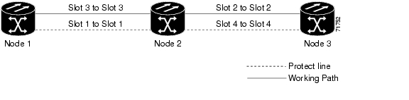
Figure 4-1 shows three ONS 15327s in a linear ADM configuration. In this example, working traffic flows from Slot 3/Node 1 to Slot 3/Node 2, and from Slot 2/Node 2 to Slot 2/Node 3. You create the protect path by placing Slot 3 in 1+1 protection with Slot 1 at Nodes 1 and 2, and Slot 2 in 1+1 protection with Slot 4 at Nodes 2 and 3.

Figure 4-1 Linear ADM Configuration

Step 2 Click the Provisioning > Protection tabs. Verify that 1+1 protection is created for the OC-N cards at the node. If the protection group has not been created, go to the "170 Create Optical Protection Groups" procedure to create them.

Step 3 Repeat Steps 1 and 2 for all other nodes you will include in the linear ADM.

Step 4 Verify that the working and protect cards in the 1+1 protection groups correspond to the physical fiber connections between the nodes, that is, working cards are fibered to working cards and protect cards are fibered to protect cards.

Step 5 Complete the "DLP-B253 Provision SONET DCC Terminations" task for the working OC-N ports on each linear ADM node.


Note If linear ADM nodes are not connected to a LAN, you will need to create the DCC terminations using a craft (direct) connection to the node. Remote provisioning is possible only after all nodes that do not have LAN connections have DCC terminations provisioned to in-service OC-N ports.


Note Terminating nodes will have one DCC termination (Nodes 1 and 3 in Figure 4-1), and intermediate nodes will have two DCC terminations (Node 2/Slot 3 and Node 2/Slot 2 in Figure 4-1).


Step 6 Verify that timing has been set up at each linear node. If not, complete the "28 Set Up Timing" procedure. If a node is using line timing, use its working OC-N card as the timing source.

Step 7 Complete the "174 Linear ADM Network Acceptance Test" procedure.

Stop. You have completed this procedure.


NTP-B174 Linear ADM Network Acceptance Test

Purpose

This procedure tests a linear ADM network.

Tools/Equipment

Test set/cables appropriate to the test circuit you will create

Prerequisite Procedures

38 Provision a Linear ADM Network

Required/As Needed

As needed

Onsite/Remote

Onsite

Security Level

Provisioning or higher


Step 1 Log into an ONS 15327 on the linear ADM network you are testing. See the "DLP-B60 Log into CTC" task for instructions. If you are already logged in, continue with Step 2.

Step 2 From the View menu choose Go to Network View.

Step 3 Click the Alarms tab.

a. Verify that the network does not have any unexplained alarms. If unexplained alarms are present, resolve them before continuing. Refer to the Cisco ONS 15327 Troubleshooting Guide.

b. Ensure that the alarm filter icon in the lower right corner is not indented. If so, click it once to turn it off. When you are done checking for alarms, click the icon again to turn alarm filtering back on. See the "DLP-B227 Disable Alarm Filtering" task for instructions.

Step 4 Complete the "DLP-B139 Export CTC Data" task to export alarm data to a file on your hard drive.

Step 5 Click the Conditions tab. Verify that the network does not have any unexplained conditions. If unexplained conditions are present, resolve them before continuing. Refer to the Cisco ONS 15327 Troubleshooting Guide.

Step 6 Complete the "DLP-B139 Export CTC Data" task to export condition data to a file on your hard drive.

Step 7 Display a linear ADM node in node view.

Step 8 Create a test circuit from that node to an adjacent linear ADM node.

For DS-1 circuits, complete the "181 Create an Automatically Routed DS-1 Circuit" procedure. When you set the circuit state, choose IS and check the Apply to drop ports check box.

For DS-3 circuits, complete the "184 Create an Automatically Routed DS-3 Circuit" procedure. When you set the circuit state, choose IS and check the Apply to drop ports check box.

Step 9 Configure the test set for the test circuit type you created:

DS-1—If you are testing an unmuxed DS-1, you must have a DSX-1 panel or a direct DS-1 interface into the ONS 15327 through the AMP Champ connectors on the MIC. Set the test set for DS-1. For information about configuring your test set, consult your test set user guide.

DS-3—If you are testing a clear channel DS-3, you must have a DSX-3 panel or a direct DS-3 interface into the ONS 15327 through the BNC connectors on the MIC. Set the test set for clear channel DS-3. For information about configuring your test set, consult your test set user guide.

Step 10 Verify the integrity of all patch cables that will be used in this test by connecting one end to the test set transmit (Tx) connector and the other end to the test set receive (Rx) connector. If the test set does not run error-free, check the cable for damage and check the test set to make sure it is set up correctly before going to the next step.

Step 11 Create a physical loopback at the circuit destination card. To do so, attach one end of a patch cable to the destination port's transmit (Tx) connector; attach the other end to the destination port's receive (Rx) connector.

Step 12 At the circuit source card:

a. Connect the transmit (Tx) connector of the test set to the circuit receive (Rx) connector.

b. Connect the test set receive (Rx) connector to the circuit transmit (Tx) connector.

Step 13 Verify that the test set displays a clean signal. If a clean signal is not displayed, repeat Steps 8 through 12 to make sure the test set and cabling are configured correctly.

Step 14 Inject BIT errors from the test set. Verify that the errors appear on the test set, indicating a complete end-to-end circuit.

Step 15 Complete the "DLP-B254 XTC Active/Standby Switch Test" task.

Step 16 Complete the "DLP-B88 Optical 1+1 Protection Test" task to test the OC-N port protection group switching.

Step 17 Set up and complete a BER test. Use the existing configuration and follow your site requirements for length of time. Record the test results and configuration.

Step 18 Remove any loopbacks, switches, or test sets from the nodes after all testing is complete. Refer to the Cisco ONS 15327 Troubleshooting Guide.

Step 19 Click the Alarms tab. Verify that the network does not have any unexplained alarms. If unexplained alarms are present, resolve them before continuing. Refer to the Cisco ONS 15327 Troubleshooting Guide.

Step 20 Delete the test circuit. See the "152 Delete Circuits" procedure for instructions.

Step 21 Display the next linear ADM node in node view and repeat Steps 8 through 20.

Step 22 If a node fails any test, repeat the test while verifying correct setup and configuration. If the test fails again, refer to the next level of support.

After all tests are successfully completed and no alarms exist in the network, the network is ready for service application.

Stop. You have completed this procedure.


NTP-B40 Provision BLSR Nodes

Purpose

This procedure provisions ONS 15327 nodes for a bidirectional line switched ring.

Tools/Equipment

None

Prerequisite Procedures

35 Verify Node Turn Up

Required/As Needed

As needed

Onsite/Remote

Onsite

Security Level

Provisioning or higher


Step 1 Complete the "DLP-B44 Install Fiber-Optic Cables for BLSR Configurations" task on page 1-46, verifying that the east port at one node is connected to the west port on an adjacent node, and this east to west port connection is used at all BLSR nodes, similar to Figure 4-2. In the figure, the OC-N drop card on the left side of the shelf is the west port, and the drop card on the right side of the shelf is the east port.

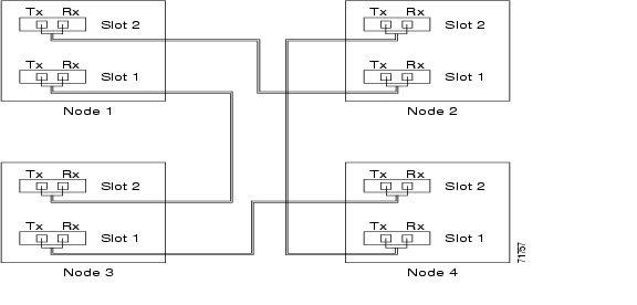
Figure 4-2 Four-Node, Two-Fiber BLSR Fiber Connection Example

Step 2 Log into an ONS 15327 that you want to configure in a BLSR. See the "DLP-B60 Log into CTC" task for instructions. If you are already logged in, continue with Step 3.

Step 3 Complete the "DLP-B253 Provision SONET DCC Terminations" task. Provision the two ports/cards that will serve as the BLSR ports at the node.


Note If an ONS 15327 is not connected to a corporate LAN, DCC provisioning must be performed through a craft (direct) connection to the node. Remote provisioning is possible only after all nodes in the network have DCC provisioned to in-service OC-N ports.


Step 4 Repeat Steps 2 and 3 at each node that will be in the BLSR. Verify that the EOC (DCC Termination Failure) and LOS (Loss of Signal) alarms are clear after you provision all the DCCs in the ring.

Step 5 Complete the "126 Create a BLSR" procedure.

Stop. You have completed this procedure.


NTP-B126 Create a BLSR

Purpose

This procedure creates a BLSR at each BLSR-provisioned node.

Tools/Equipment

None

Prerequisite Procedures

35 Verify Node Turn Up

40 Provision BLSR Nodes

Required/As Needed

Required

Onsite/Remote

Onsite or remote

Security Level

Provisioning or higher


Step 1 Log into an ONS 15327 node on the network where you will create the BLSR. See the "DLP-B60 Log into CTC" task for instructions. If you are already logged in, continue with Step 2.

Step 2 From the View menu choose Go to Network View.

Step 3 Click the Provisioning > BLSR tabs.

Step 4 Click Create BLSR.

Step 5 On the BLSR Creation dialog box ( Figure 4-3), set the BLSR properties:

Ring Type—Choose the BLSR ring type, either two-fiber or four-fiber.

Speed—Choose the BLSR ring speed: OC-12 or OC-48. The speed must match the OC-N speed of the BLSR trunk (span) cards.

Ring ID—Assign a ring ID (a number between 0 and 9999).

Reversion time—Set the amount of time that will pass before the traffic reverts to the original working path following a ring switch. The default is 5 minutes. Ring reversions can be set to Never.

Figure 4-3 Setting BLSR Properties

Step 6 Click Next. If CTC displays a network graphic, go to Step 7. If CTC determines that a BLSR cannot be created, for example, not enough optical cards are installed or it finds circuits with UPSR selectors, a "Cannot Create BLSR" message appears. If this occurs, complete the following steps:

a. Click OK.

b. On the Create BLSR window, click Excluded Nodes. Review the information explaining why the BLSR could not be created, then click OK.

c. Depending on the problem, click Back to start over or click Cancel to cancel the operation.

d. Complete the "40 Provision BLSR Nodes" procedure, making sure all steps are completed accurately, then start this procedure again.

Step 7 In the network graphic, double-click a BLSR span line. If the span line is DCC connected to other BLSR cards comprising a complete ring, the lines turn blue and the Finish button appears. If the lines do not form a complete ring, double-click span lines until a complete ring is formed. When the ring is DCC connected, go to Step 8.

Step 8 Click Finish. If CTC displays the BLSR window with the BLSR you created, go to Step 9. If CTC displays a "Cannot Create BLSR" or "Error While Creating BLSR" message:

a. Click OK.

b. On the Create BLSR window, click Excluded Nodes. Review the information explaining why the BLSR could not be created, then click OK.

c. Depending on the problem, click Back to start over or click Cancel to cancel the operation.

d. Complete the "40 Provision BLSR Nodes" procedure, making sure all steps are completed accurately, then start this procedure again.


Note Some or all of the following alarms may briefly appear during BLSR setup: E-W MISMATCH, RING MISMATCH, APSCIMP, APSDFLTK, or BLSROSYNC.


Step 9 Verify the following:

On the network view graphic, a green span line appears between all BLSR nodes.

All E-W MISMATCH, RING MISMATCH, APSCIMP, DFLTK, and BLSROSYNC alarms are cleared. See the Cisco ONS 15327 Troubleshooting Guide for alarm troubleshooting.

Step 10 Complete the "175 BLSR Acceptance Test" procedure.

Stop. You have completed this procedure.


NTP-B175 BLSR Acceptance Test

Purpose

This procedure tests a two-fiber BLSR.

Tools/Equipment

Test set and cables appropriate for the test circuit

Prerequisite Procedures

40 Provision BLSR Nodes

126 Create a BLSR

Required/As Needed

As needed

Onsite/Remote

Onsite

Security Level

Provisioning or higher


Note This procedure requires that you create test circuits and perform span switches around the ring. For clarity, "Node 1" refers to the login node where you begin the procedure. "Node 2" refers to the node connected to the east OC-N trunk (span) card of Node 1, "Node 3" refers to the node connected to the east OC-N trunk card of Node 2, and so on.


Step 1 Log into one of the ONS 15327s on the BLSR you are testing. (This node will be called Node 1.) See the "DLP-B60 Log into CTC" task for instructions. If you are already logged in, continue with Step 2.

Step 2 From the View menu choose Go to Network View.

Step 3 Click the Alarms tab.

a. Verify that the network does not have any unexplained alarms. If unexplained alarms are present, resolve them before continuing. Refer to the Cisco ONS 15327 Troubleshooting Guide.

b. Ensure that the alarm filter icon in the lower right corner is not indented. If so, click it once to turn it off. When you are done checking for alarms, click the icon again to turn alarm filtering back on. See the "DLP-B227 Disable Alarm Filtering" task for instructions.

Step 4 Complete the "DLP-B139 Export CTC Data" task to export alarm data to a file on your hard drive.

Step 5 Click the Conditions tab. Verify that the network does not have any unexplained conditions. If unexplained conditions are present, resolve them before continuing. Refer to the Cisco ONS 15327 Troubleshooting Guide.

Step 6 Complete the "DLP-B139 Export CTC Data" task to export condition data to a file on your hard drive.

Step 7 On the network view, double-click Node 1.

Step 8 Complete the "DLP-B217 BLSR Exercise Ring Test" task.

Step 9 Create a test circuit from Node 1 to the node connected to the east OC-N trunk card of Node 1. (This node will be called Node 2.)

For DS-1 circuits, complete the "181 Create an Automatically Routed DS-1 Circuit" procedure. When you set the circuit state, choose IS and check the Apply to drop ports check box.

For DS-3 circuits, complete the "184 Create an Automatically Routed DS-3 Circuit" procedure. When you set the circuit state, choose IS and check the Apply to drop ports check box.

Step 10 Configure the test set for the test circuit type you created:

DS-1—If you are testing an unmuxed DS-1, you must have a DSX-1 panel or a direct DS-1 interface into the ONS 15327 through the AMP Champ connectors on the MIC. Set the test set for DS-1. For information about configuring your test set, consult your test set user guide.

DS-3—If you are testing a clear channel DS-3, you must have a DSX-3 panel or a direct DS-3 interface into the ONS 15327 through the BNC connectors on the MIC. Set the test set for clear channel DS-3. For information about configuring your test set, consult your test set user guide.

Step 11 Verify the integrity of all patch cables that will be used in this test by connecting the test set transmit (Tx) connector to the test set receive (Rx) connector. If the test set does not run error-free, check the cable for damage and check the test set to make sure it is set up correctly before going to the next step.

Step 12 Create a physical loopback at the circuit destination card: attach one end of a patch cable to the destination port transmit (Tx) connector; attach the other end to the port receive (Rx) connector.

Step 13 At the circuit source card:

a. Connect the transmit (Tx) connector of the test set to the circuit receive (Rx) connector.

b. Connect the test set receive (Rx) connector to the circuit transmit (Tx) connector.

Step 14 Verify that the test set displays a clean signal. If a clean signal is not displayed, repeat Steps 9 through 13 to make sure the test set and cabling are configured correctly.

Step 15 Inject BIT errors from the test set. Verify that the errors display at the test set, verifying a complete end-to-end circuit.

Step 16 Complete the "DLP-B254 XTC Active/Standby Switch Test" task.

Step 17 Complete the "DLP-B91 BLSR Ring Switch Test" task at Node 1.

Step 18 Set up and complete a BER test on the test circuit. Use the existing configuration and follow your site requirements for length of time. Record the test results and configuration.

Step 19 Complete the "152 Delete Circuits" procedure for the test circuit.

Step 20 Repeating Steps 7 through 19 for Nodes 2 and higher, work your way around the BLSR, testing each node and span in the ring. Work your way around the BLSR creating test circuits between every two consecutive nodes.

Step 21 After you test the entire ring, remove any loopbacks and test sets from the nodes.

Step 22 If a node fails any test, repeat the test while verifying correct setup and configuration. If the test fails again, refer to the next level of support.

After all tests are successfully completed and no alarms exist in the network, the network is ready for service application. Continue with "Create Circuits and VT Tunnels."

Stop. You have completed this procedure.


DLP-B217 BLSR Exercise Ring Test

Purpose

This task tests the BLSR functionality without switching traffic. Ring exercise conditions are reported and cleared within 10 to 15 seconds.

Tools/Equipment

None

Prerequisite Procedures

60 Log into CTC

Required/As Needed

As needed

Onsite/Remote

Onsite

Security Level

Provisioning or higher


Step 1 From the View menu choose Go to Network View.

Step 2 Click the Provisioning > BLSR tabs.

Step 3 Click the row of the BLSR you will exercise, then click Edit.

Step 4 Right-click the west port of any BLSR node and choose Set West Protection Operation. (To move a graphic icon, press Ctrl while you drag and drop it to a new location.)


Note For two-fiber BLSRs, the squares on the node icons represent the BLSR working and protect channels. You can right-click either channel.


Step 5 On the Set West Protection Operation dialog box, choose EXERCISE RING from the drop-down menu. Click OK.

Step 6 On the Confirm BLSR Operation dialog box, click Yes.

On the network view graphic, an E appears on the BLSR channel where you invoked the exercise. The E will display for 10 to 15 seconds, then disappear.

Step 7 In the CTC window, click the History tab. Verify that the node where you exercised the ring has an EXERCISE-RING (Exercising Ring Successfully) condition appear. Other conditions displayed include EXERCISE-RING-REQ and FE-EXERCISING-RING.

If you do not see any BLSR exercise conditions, click the Filter button and verify that filtering is not turned on. Also, check that alarms and conditions are not suppressed for a node or BLSR trunk cards. See the "72 Suppress and Discontinue Alarm Suppression" procedure for more information.

Step 8 Click the Alarms tab. Verify that the network does not have any unexplained alarms. If unexplained alarms are present, resolve them before continuing. Refer to the Cisco ONS 15327 Troubleshooting Guide.

Step 9 From the File menu choose Close to close the BLSR window.

Step 10 Return to your originating procedure (NTP).


DLP-B91 BLSR Ring Switch Test

Purpose

This task verifies that protection switching is working correctly in a BLSR.

Tools/Equipment

None

Prerequisite Procedures

60 Log into CTC

Required/As Needed

Required

Onsite/Remote

Onsite

Security Level

Provisioning or higher


Step 1 In the network view click the Provisioning > BLSR tabs.

Step 2 Click the row of the BLSR you will switch, then click Edit.

Step 3 Right-click any BLSR node west port and choose Set West Protection Operation. (To move a graphic icon, click it, then press Ctrl while you drag and drop it to a new location.)


Note The squares on the node icons represent the BLSR working and protect channels. You can right-click either channel.


Step 4 On the Set West Protection Operation dialog box, choose FORCE RING from the drop-down menu. Click OK.

Step 5 Click Yes on the two Confirm BLSR Operation dialog boxes that appear.

On the network view graphic, an F appears on the working BLSR channel where you invoked the Force Ring switch. The BLSR span lines turn purple where the Force was invoked, and all span lines between other BLSR nodes turn green.

Step 6 Click the Conditions tab, then click Retrieve.

Step 7 Verify that the following conditions are reported on the node where you invoked the Force switch on the west port:

FORCE-REQ-RING—A Force Switch Request On Ring condition is reported against the span's working slot on the west side of the node.

RING-SW-EAST—A Ring Switch Active on the east side condition is reported against the working span on the east side of the node.


Note Make sure the Filter button in the lower right corner of the window is off. Click the Node column to sort conditions by node.


Step 8 Verify that the following conditions are reported on the node that is connected to the west line of the node where you performed the switch:

FE-FRCDWKSWPR-RING—A Far-End Working Facility Forced to Switch to Protection condition is reported against the working span on the east side of the node.

RING-SW-WEST—A Ring Switch Active on the west side condition is reported against the working span on the west side of the node.

Step 9 Verify the BLSR line status on each node:

a. In node view, click Maintenance > BLSR.

b. Verify the following:

The line states are shown as Stby/Stby on the west side of the node and Act/Act on the east side of the node where you invoked the Force Ring switch.

The line states are shown as Stby/Stby on the east side of the node and Act/Act on the west side of the node that is connected to the west line of the node where you invoked the Force Ring switch.

The line states are shown as Act/Act on both East and west sides of the remaining nodes in the ring.

Step 10 From network view, click the Alarms tab.

a. Verify that the network does not have any unexplained alarms. If unexplained alarms are present, resolve them before continuing. Refer to the Cisco ONS 15327 Troubleshooting Guide.

b. Ensure that the alarm filter icon in the lower right corner is not indented. If so, click it once to turn it off. When you are done checking for alarms, click the icon again to turn alarm filtering back on. See the "DLP-B227 Disable Alarm Filtering" task for instructions.

Step 11 Display the BLSR window where you invoked the Force Ring switch (the window may be hidden by the CTC window).

Step 12 Right-click the west port of the BLSR node where you invoked the Force Ring switch and choose Set West Protection Operation.

Step 13 On the Set West Protection Operation dialog box, choose CLEAR from the drop-down menu. Click OK.

Step 14 Click Yes on the Confirm BLSR Operation dialog box.

On the network view graphic, the Force Ring switch is removed, the F indicating the switch is removed, and the span lines between BLSR nodes are purple and green. The span lines may take a few moments to change color.

Step 15 From network view, click the Conditions tab. Verify that all conditions raised in this procedure are cleared from the network. If unexplained conditions are present, resolve them before continuing.

Step 16 Verify the BLSR line status on each node:

a. From node view, click Maintenance > BLSR.

b. Verify that the line states are shown as Act/Stby on both the East and west sides of each node in the ring.

Step 17 Right-click the east port of BLSR node and choose Set East Protection Operation.

Step 18 On the Set East Protection Operation dialog box, choose FORCE RING from the drop-down menu. Click OK.

Step 19 Click Yes on the two Confirm BLSR Operation dialog boxes that appear.

On the network view graphic, an F appears on the working BLSR channel where you invoked the Force Ring switch. The BLSR span lines are purple where the Force was invoked, and all span lines between other BLSR nodes are green. The span lines may take a few moments to change color.

Step 20 Click the Conditions tab, then click Retrieve.

Step 21 Verify that the following conditions are reported on the node where you invoked the Force Ring switch on the east port:

FORCE-REQ-RING—A Force Switch Request On Ring condition is reported against the working span on the east side of the node.

RING-SW-WEST—A Ring Switch Active on the west side condition is reported against the working span on the east side of the node.


Note Make sure the Filter button in the lower right corner of the window is off. Click the Node column to sort conditions by node.


Step 22 Verify that the following conditions are reported on the node that is connected via the east line to the node where you performed the switch:

FE-FRCDWKSWPR-RING—A Far-End Working Facility Forced to Switch to Protection condition is reported against the working span on the west side of the node.

RING-SW-EAST—A Ring Switch Active on the east side condition is reported against the working span on the west side of the node.

Step 23 Verify the BLSR line status on each node:

a. From node view, click Maintenance > BLSR.

b. Verify the following:

The line states are shown as Stby/Stby on the east side of the node and Act/Act on the west side of the node where you invoked the Force Ring switch.

The line states are shown as Stby/Stby on the west side of the node and Act/Act on the east side of the node that is connected to the east line of the node where you invoked the Force Ring switch.

The line states are shown as Act/Act on both East and west sides of the remaining nodes in the ring.

Step 24 From network view, click the Alarms tab. Verify that the network does not have any unexplained alarms. If unexplained alarms are present, resolve them before continuing. Refer to the Cisco ONS 15327 Troubleshooting Guide.

Step 25 Display the BLSR window where you invoked the Force Ring switch (the window may be hidden by the CTC window).

Step 26 Right-click the west port of the BLSR node where you invoked the Force Ring switch and choose Set East Protection Operation.

Step 27 On the Set East Protection Operation dialog box, choose CLEAR from the drop-down menu. Click OK.

Step 28 Click Yes on the Confirm BLSR Operation dialog box.

On the network view graphic, the Force Ring switch is removed, the F indicating the switch is removed, and the span lines between BLSR nodes will be purple and green. The span lines may take a few moments to change color.

Step 29 From network view, click the Conditions tab. Verify that all conditions raised in this procedure are cleared from the network. If unexplained conditions are present, resolve them before continuing.

Step 30 Verify the BLSR line status on each node:

a. From node view, click Maintenance > BLSR.

b. Verify that the line states are shown as Act/Stby on both the East and west sides of each node in the ring.

Step 31 From the File menu choose Close to close the BLSR window.

Step 32 Return to your originating procedure (NTP).


NTP-B44 Provision UPSR Nodes

Purpose

This procedure provisions nodes for inclusion in a unidirectional path switched ring (UPSR). A UPSR is created after the fiber connections are made.

Tools/Equipment

None

Prerequisite Procedures

35 Verify Node Turn Up

Required/As Needed

As needed

Onsite/Remote

Onsite

Security Level

Provisioning or higher


Step 1 Verify that the fiber is correctly connected to the UPSR trunk (span) OC-N cards similar to Figure 4-4.

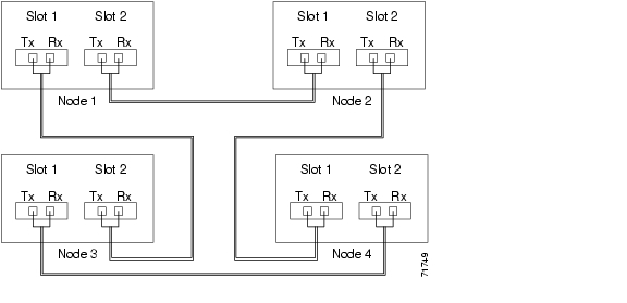
Figure 4-4 UPSR Fiber Connection Example

Step 2 Log into an ONS 15327 in the UPSR you are turning up. See the "DLP-B60 Log into CTC" task for instructions. If you are already logged in, continue with Step 3.

Step 3 Complete the "DLP-B253 Provision SONET DCC Terminations" task for the two cards/ports that will serve as the UPSR ports on the node, for example, Slot 2 (OC-48)/Node 1 and Slot 1 (OC-48)/ Node 1.


Note If an ONS 15327 is not connected to a corporate LAN, DCC provisioning must be performed through a craft (direct) connection. Remote provisioning is possible only after all nodes in the network have DCC terminations provisioned to in-service OC-N ports.


Step 4 Repeat Steps 2 and 3 for each node in the UPSR.

Step 5 Complete the "177 UPSR Acceptance Test" procedure.

Stop. You have completed this procedure.


NTP-B177 UPSR Acceptance Test

Purpose

This procedure tests a UPSR.

Tools/Equipment

Test set and cables appropriate to the test circuit you will create

Prerequisite Procedures

44 Provision UPSR Nodes

Required/As Needed

As needed

Onsite/Remote

Onsite

Security Level

Provisioning or higher


Step 1 Complete the "DLP-B60 Log into CTC" task. If you are already logged in, continue with Step 2.

Step 2 From the View menu choose Go to Network View.

Step 3 Click the Alarms tab.

a. Verify that the network does not have any unexplained alarms. If unexplained alarms are present, resolve them before continuing. Refer to the Cisco ONS 15327 Troubleshooting Guide.

b. Ensure that the alarm filter icon in the lower right corner is not indented. If so, click it once to turn it off. When you are done checking for alarms, click the icon again to turn alarm filtering back on. See the "DLP-B227 Disable Alarm Filtering" task for instructions.

Step 4 Complete the "DLP-B139 Export CTC Data" task to export alarm data to a file on your hard drive.

Step 5 Click the Conditions tab. Verify that the network does not have any unexplained conditions. If unexplained conditions are present, resolve them before continuing. Refer to the Cisco ONS 15327 Troubleshooting Guide.

Step 6 Complete the "DLP-B139 Export CTC Data" task to export condition data to a file on your hard drive.

Step 7 On the network map, double-click the node that you logged into in Step 1.

Step 8 Create a test circuit from that node to the next adjacent UPSR node.

For DS-1 circuits, complete the "181 Create an Automatically Routed DS-1 Circuit" procedure. When you set the circuit state, choose IS and check the Apply to drop ports check box.

For DS-3 circuits, complete the "184 Create an Automatically Routed DS-3 Circuit" procedure. When you set the circuit state, choose IS and check the Apply to drop ports check box.

Step 9 Configure the test set for the test circuit type you created:

DS-1—If you are testing an unmuxed DS-1, you must have a DSX-1 panel or a direct DS-1 interface into the ONS 15327 through the AMP Champ connectors on the MIC. Set the test set for DS-1. For information about configuring your test set, consult your test set user guide.

DS-3—If you are testing a clear channel DS-3, you must have a DSX-3 panel or a direct DS-3 interface into the ONS 15327 through the BNC connectors on the MIC. Set the test set for clear channel DS-3. For information about configuring your test set, consult your test set user guide.

Step 10 Verify the integrity of all patch cables that will be used in this test by connecting one end to the test set transmit (Tx) connector and the other end to the test set receive (Rx) connector. If the test set does not run error-free, check the cable for damage and check the test set to make sure it is set up correctly before continuing.

Step 11 Create a physical loopback at the circuit destination card:

a. Attach one end of a patch cable to the destination port transmit (Tx) connector.

b. Attach the other end to the port receive (Rx) connector.

Step 12 At the circuit source card:

a. Connect the transmit (Tx) connector of the test set to the circuit receive (Rx) connector.

b. Connect the test set receive (Rx) connector to the circuit transmit (Tx) connector.

Step 13 Verify that the test set displays a clean signal. If a clean signal is not displayed, repeat Steps 1 through 10 to make sure the test set and cabling are configured correctly.

Step 14 Inject BIT errors from the test set. To verify that you have a complete end-to-end circuit, verify that the errors display at the test set.

Step 15 Complete the "DLP-B254 XTC Active/Standby Switch Test" task.

Step 16 From the View menu choose Go to Network View.

Step 17 Click one of the two spans leaving the circuit source node and complete the "DLP-B94 UPSR Protection Switching Test" task for instructions.

Although a service interruption under 60 ms may occur, the test circuit should continue to work before, during, and after the switches. If the circuit stops working, do not continue. Contact your next level of support.

Step 18 In network view, click the other circuit source span and complete the "DLP-B94 UPSR Protection Switching Test" task for instructions.

Although a service interruption under 60 ms may occur, the test circuit should continue to work before, during, and after the switches. If the circuit stops working, do not continue. Contact your next level of support.

Step 19 Set up and complete a BER Test. Use the existing configuration and follow your site requirements for the length of time. Record the test results and configuration.

Step 20 Complete the "152 Delete Circuits" procedure for the test circuit.

Step 21 Remove any loopbacks, switches, or test sets from the nodes after all testing is complete. Refer to the Cisco ONS 15327 Troubleshooting Guide.

Step 22 View the alarms and conditions on each node and record results by exporting them to a file. See the "DLP-B139 Export CTC Data" task for instructions.

Step 23 Repeat Steps 8 through 22 for each node on the network.

Step 24 If a node fails any test, repeat the test while verifying correct setup and configuration. If the test fails again, refer to the next level of support.

After all tests are successfully completed and no alarms exist in the network, the network is ready for service application. Continue with "Create Circuits and VT Tunnels."

Stop. You have completed this procedure.


DLP-B94 UPSR Protection Switching Test

Purpose

This task verifies that a UPSR span is switching correctly.

Tools/Equipment

None

Prerequisite Procedures

60 Log into CTC

Required/As Needed

Required

Onsite/Remote

Onsite

Security Level

Provisioning or higher


Step 1 From the View menu choose Go to the Network View.

Step 2 Right-click a network span and choose Circuits.

The Circuits on Span dialog box displays the UPSR circuits, including circuit names, locations, and a color code showing which circuits are active on the span.

Step 3 Click the Perform UPSR span switching field and choose FORCE SWITCH AWAY from the drop-down menu. Click Apply.

Step 4 In the Confirm UPSR Switch dialog box, click Yes.

Step 5 In the Protection Switch Result dialog box, click OK.

In the Circuits on Span dialog box, the Switch State for all circuits is Force. Unprotected circuits will not switch.

Step 6 Click the Perform UPSR span switching field and choose CLEAR from the drop-down menu. Click Apply. Click Yes to confirm.

Step 7 In the Confirm UPSR Switch dialog box, click Yes.

Step 8 In the Protection Switch Result dialog box, click OK.

In the Circuits on Span window, the Switch State for all UPSR circuits is CLEAR.

Step 9 Return to your originating procedure (NTP).


NTP-B46 Subtend a UPSR from a BLSR

Purpose

This procedure subtends a UPSR from an existing BLSR.

Tools/Equipment

One BLSR node must have OC-N cards and fibers to carry the UPSR.

Prerequisite Procedures

175 BLSR Acceptance Test

Required/As Needed

As needed

Onsite/Remote

Onsite

Security Level

Provisioning or higher


Step 1 In the node that will subtend the UPSR (Node 3 in Figure 4-5), install the two (east/west) OC-N cards that will serve as the UPSR trunk (span) cards (Node 3, Slots 3 and 4). See the "NTP-B218 Install the Optical and Ethernet Cards" procedure on page 1-23. If they are already installed, go to Step 2.

Step 2 Attach fibers from these cards to the UPSR trunk cards on the neighbor UPSR node or nodes.

Step 3 Log into the ONS 15327 that will subtend the UPSR. See the "DLP-B60 Log into CTC" task for instructions.

Step 4 Complete the "DLP-B253 Provision SONET DCC Terminations" task for each OC-N card that will carry the UPSR.

Step 5 Log into the UPSR node that connects to the node in Step 3.

Step 6 Complete the "DLP-B253 Provision SONET DCC Terminations" task for each OC-N card that will carry the UPSR.

Step 7 Repeat Step 6 for each node in the UPSR.

Step 8 From the View menu choose Go To Network View.

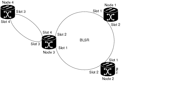
Figure 4-5 UPSR Subtended from a BLSR

Step 9 Complete the "177 UPSR Acceptance Test" procedure.

Stop. You have completed this procedure.


NTP-B47 Subtend a BLSR from a UPSR

Purpose

This procedure subtends a BLSR from an existing UPSR.

Tools/Equipment

One UPSR node must have OC-N cards and fibers to carry the BLSR.

Prerequisite Procedures

177 UPSR Acceptance Test

Required/As Needed

As needed

Onsite/Remote

Onsite

Security Level

Provisioning or higher


Step 1 In the UPSR node that will subtend the BLSR, install the two (east and west) OC-N cards that will serve as the BLSR trunk (span) cards (in Figure 4-5, Node 3, Slots 1 and 2). See the "NTP-B218 Install the Optical and Ethernet Cards" procedure on page 1-23.

Step 2 Attach fibers from the cards in Step 1 to the BLSR trunk cards on another BLSR node or nodes. In Figure 4-5, Slot 1/Node 3 connects to Slot 2/Node 2, and Slot 2/Node 3 connects to Slot 1/Node 1.

Step 3 Log into the ONS 15327 that will subtend the BLSR (the node in Step 1). See the "DLP-B60 Log into CTC" task for instructions. If you are already logged in, continue with Step 4.

Step 4 Create the DCCs on both OC-N trunk cards (east and west) that will carry the BLSR. See the "DLP-B253 Provision SONET DCC Terminations" task for instructions.

Step 5 Create the subtending BLSR:

a. Complete the "40 Provision BLSR Nodes" procedure for each node that will be in the BLSR. If you have already provisioned the BLSR, perform this procedure for the subtending node only.

b. Complete the "126 Create a BLSR" procedure. Include the node in Step 3 (the node that will subtend the BLSR) in the BLSR.

Step 6 From the View menu choose Go to the Network View to see the subtending ring.

Stop. You have completed this procedure.


NTP-B48 Subtend a BLSR from a BLSR

Purpose

This procedure subtends a BLSR from an existing BLSR.

Tools/Equipment

One BLSR node must have OC-N cards and fibers needed to carry the second BLSR.

Prerequisite Procedures

None

Required/As Needed

As needed

Onsite/Remote

Onsite

Security Level

Provisioning or higher


Note This procedure assumes that all nodes are configured for the BLSR. If you need to add a node to a BLSR, see the "12 Add a BLSR Node" procedure.


Step 1 Log into the node that will subtend the BLSR. See the "DLP-B60 Log into CTC" task for instructions. If you are already logged in, continue with Step 2.

Step 2 Install the OC-N cards that will serve as the BLSR trunk (span) cards if they are not already installed. See the "NTP-B218 Install the Optical and Ethernet Cards" procedure on page 1-23.

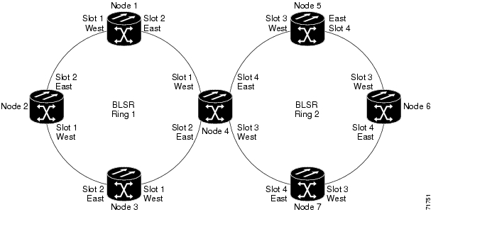
Figure 4-6 shows two BLSRs shared by one ONS 15327. Ring 1 runs on Nodes 1, 2, 3, and 4. Ring 2 runs on Nodes 4, 5, 6, and 7 and represents the subtending ring added by this procedure. Two BLSR rings, Ring 1 and Ring 2, are provisioned on Node 4. Ring 1 uses cards in Slots 1 and 2, and Ring 2 uses cards in Slots 3 and 4.


Note Although different node IDs are used for the two BLSRs shown in Figure 4-6, nodes in different BLSRs can use the same node ID.


Figure 4-6 BLSR Subtended from a BLSR

Step 3 Attach fibers from the trunk cards in the subtending node to the BLSR trunk cards on its two neighboring BLSR nodes. In Figure 4-6, Node 4/Slot 3 connects to Node 7/Slot 4, and Node 4/Slot 4 connects to Node 5/Slot 3.

Step 4 Create the DCCs on the first OC-N card that will carry the BLSR. See the "DLP-B253 Provision SONET DCC Terminations" task for instructions.

Step 5 Repeat Step 4 for the second OC-N trunk card that will carry the BLSR.

Step 6 Complete the "40 Provision BLSR Nodes" procedure for each node that will be in the BLSR. If you have already provisioned the BLSR, perform this procedure for the subtending node only.

Step 7 If the subtending BLSR is not already created, complete the "126 Create a BLSR" procedure to provision the new BLSR. The subtending BLSR must have a ring ID that differs from the ring ID of the first BLSR. The subtending node can have one Node ID that is used in both BLSRs, or a different Node ID for each BLSR. For example, the same node can be Node 4 in BLSR 1 and Node 2 in BLSR 2.

Step 8 Display the network view to see the subtending ring.

Step 9 Complete the "175 BLSR Acceptance Test" procedure.

Stop. You have completed this procedure.


hometocprevnextglossaryfeedbacksearchhelp

Posted: Mon Feb 25 07:24:12 PST 2008
All contents are Copyright © 1992--2008 Cisco Systems, Inc. All rights reserved.
Important Notices and Privacy Statement.