cc/td/doc/product/ong/15327/r34userd
hometocprevnextglossaryfeedbacksearchhelp
PDF

Table Of Contents

Add and Remove Nodes

Before You Begin

NTP-B12 Add a BLSR Node

DLP-B302 Check BLSR or UPSR Alarms and Conditions

DLP-B242 Create a BLSR on a Single Node

DLP-B303 Initiate a BLSR Force Ring Switch

DLP-B194 Clear a BLSR Force Ring Switch

NTP-B213 Remove a BLSR Node

DLP-B304 Verify BLSR Pass-Through Circuits

DLP-B195 Verify Timing in a Reduced Ring

DLP-B196 Delete a BLSR from a Single Node

NTP-B105 Add a UPSR Node

NTP-B106 Remove a UPSR Node

DLP-B197 Initiate a UPSR Force Switch

DLP-B198 Clear a UPSR Switch


Add and Remove Nodes


This chapter explains how to add and remove nodes Cisco ONS 15327 nodes from bidirectional line switched rings (BLSRs) and unidirectional path switched rings (UPSRs).

Before You Begin

Before performing any of the following procedures, complete the "195 Document Existing Provisioning" procedure. Also investigate all alarms and clear any trouble conditions. Refer to the Cisco ONS 15327 Troubleshooting Guide as necessary.

This section lists the chapter procedures (NTPs). Turn to a procedure for applicable tasks (DLPs).

1. 12 Add a BLSR Node—Complete as needed.

2. 213 Remove a BLSR Node—Complete as needed.

3. 105 Add a UPSR Node—Complete as needed.

4. 106 Remove a UPSR Node—Complete as needed.

NTP-B12 Add a BLSR Node

Purpose

This procedure expands a BLSR by adding a node.

Tools/Equipment

Fiber for new node connections

Prerequisite Procedures

Cards must be installed and node turn-up procedures completed on the node that will be added to the BLSR. See Chapter 1, "Install Hardware," and "Turn Up Node."

NTP-B108 Back Up the Database, page 14-6

Required/As Needed

As needed

Onsite/Remote

Onsite

Security Level

Provisioning or higher


Caution Adding a BLSR node can be service affecting and should be performed during a maintenance window.


Note If the node you are adding to the BLSR is not provisioned as an external network element (ENE) is on the same subnet as other BLSR nodes and CTC computers are directly connected to BLSR nodes, you expect a CTC computer will connect to it,


Step 1 Draw a diagram of the BLSR where you will add the node. In the diagram, identify the east and west BLSR OC-N trunk (span) cards that will connect to the new node. This information is essential to complete this procedure without error. Figure 13-1 shows a drawing of a three-node, two-fiber BLSR that uses Slots 1 and 2 for the BLSR trunk cards.

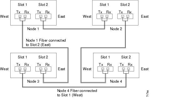
Figure 13-1 Three-Node Two-Fiber BLSR Before a Fourth Node Is Added

Step 2 Verify the card installation on the new node using the "24 Verify Card Installation" procedure. Verify that the OC-N cards that will be the BLSR trunk (span) cards match the BLSR optical rate. For example, if the BLSR is OC-48, the new node must have OC-48 cards installed. If the OC-N cards are not installed or the optical rates do not match the BLSR, complete the "NTP-B218 Install the Optical and Ethernet Cards" procedure on page 1-23.

Step 3 Verify that fiber is available to connect the new node to the existing nodes. Refer to the diagram drawn in Step 1.

Step 4 Complete the "35 Verify Node Turn Up" procedure. In order to have CTC visibility to the new node after it is added, you must be an authorized user on the node and you must have IP connectivity to the node.

Step 5 Log into a node that is in the BLSR. See the "DLP-B60 Log into CTC" task.

Step 6 Complete the "DLP-B302 Check BLSR or UPSR Alarms and Conditions" task to verify that the BLSR is free of major alarms or problems. If trouble is indicated (for example, a major alarm exists), resolve the problem before proceeding. See "Manage Alarms" or, if necessary, refer to the Cisco ONS 15327 Troubleshooting Guide.

Step 7 Click the Provisioning > BLSR tabs.

Step 8 On paper, record the Ring ID, Ring Type, Line Rate, and Ring Reversion.

Step 9 From the Node column, record the Node IDs in the BLSR. The Node IDs are the numbers in parentheses next to the node name.

Step 10 Log into the new node:

If the node has a LAN connection and is displayed on the network map, from the View menu, choose Go to Other Node, then choose the new node from the Select Node to Go to pull-down menu on the Select Node dialog box and click OK.

If the new node is not connected to the network, log into it directly using the "DLP-B60 Log into CTC" task.

Step 11 Click the Alarms tab. Verify that no critical or major alarms are present, nor any facility alarms, such as LOS, LOF, AIS-L, SF, and SD. If trouble is indicated (for example, a major alarm exists), resolve the problem before proceeding. See "Manage Alarms"or, if necessary, refer to the Cisco ONS 15327 Troubleshooting Guide.

Step 12 Complete the following steps if the node is on the same subnet as other BLSR nodes, it is not provisioned as an external network element (see "169 Set Up CTC Network Access" procedure), and a CTC computer will directly connect to the node while other CTC computers are directly connected to other BLSR nodes. If not, continue with Step 13.

a. Click the Provisioning > Network > General tabs. View the IP Address and Net/Subnet Mask Length fields to verify the node is on the same subnet as other BLSR nodes.

b. Click the Static Route tab and click Create.

c. In the Create Static Route dialog box, enter the following settings:

Destination IP address: IP address of CTC computer directly connected to the node

Net Mask: 255.255.255.255

Next Hop: IP address of the Cisco ONS 15327

Cost: 1

d. Click OK.

Step 13 Using the information recorded in Steps 8 and 9 and the diagram created in Step 1, create a BLSR on the new node. See the "DLP-B242 Create a BLSR on a Single Node" task.

Step 14 (Optional) Create test circuits, making sure they pass through the BLSR trunk cards, and run test traffic through the node to ensure that the cards are functioning properly. See the "189 Create a Manually Routed Optical Circuit" procedure and the "62 Test Optical Circuits" procedure for information.

Step 15 Create the DCC terminations on the new node. See the "DLP-B253 Provision SONET DCC Terminations" task.


Note Creating the DCC terminations causes the SDCC Termination Failure and Loss of Signal alarms to appear. These alarms will remain active until you connect the node to the BLSR.


Note If you map the K3 byte to another byte (such as E2), you must remap the line cards on either side of the new node to the same byte. See the "DLP-A89 Remap the K3 Byte" task on page 5-16.


Step 16 Log into a BLSR node that will connect to the new node using one of the login options in Step 10.

Step 17 Referring to the diagram created in Step 1, complete the "DLP-B303 Initiate a BLSR Force Ring Switch" task on the node that will connect to the new node via its west port.

Step 18 Referring to the diagram created in Step 1, complete the "DLP-B303 Initiate a BLSR Force Ring Switch" task on the node that will connect to the new node via its east port.

Step 19 Click the Alarms tab. If unexpected critical or major alarms are present, resolve them before you continue. If necessary, refer to the alarm troubleshooting procedures in the Cisco ONS 15327 Troubleshooting Guide.

Step 20 Following the diagram created in Step 1, remove the fiber connections from the two nodes that will connect to the new node.

a. Remove the west fiber from the node that will connect to the east port of the new node. In the Figure 13-1 example, this is Node 1/Slot 1

b. Remove the east fiber from the node that will connect to the west port of the new node. In the Figure 13-1 example, this is Node 4/Slot 2.

Step 21 Connect fibers from the adjacent nodes to the new node following the diagram created in Step 1. Connect the west port to the east port and the east port to the west port.

Step 22 Display the newly added node in node view.

Step 23 Click the Provisioning > BLSR tabs.

Step 24 Click Ring Map. Verify that the new node appears on the Ring Map with the other BLSR nodes, then click OK.

Step 25 From the View menu, choose Go to Network View and verify the following:

a. Click the Provisioning > BLSR tabs. Verify that the new node is displayed under the Node column.

b. Click the Alarms tab. Verify that BLSR alarms such as RING MISMATCH, E-W MISMATCH, PRC-DUPID (duplicate node ID), and APSCDFLTK (default K) are not present.

If the new node does not appear in the Node column, or if BLSR alarms are displayed, log into the new node and verify that the BLSR is provisioned on it correctly with the information from Steps 8 and 9. If the node still does not appear, or if alarms persist, refer to the Cisco ONS 15327 Troubleshooting Guide.

Step 26 Click the Circuits tab. Wait until all the circuits are discovered. The circuits that pass through the new node will be shown as incomplete.

Step 27 In network view, right-click the new node and choose Update Circuits With The New Node from the shortcut menu. Verify that the number of updated circuits displayed in the dialog box is correct.

Step 28 If incomplete circuits still appear, refer to the Cisco ONS 15327 Troubleshooting Guide.

Step 29 Click the History tab. Verify that BLSR_RESYNC conditions are present for every node in the BLSR.

Step 30 Complete the "DLP-B194 Clear a BLSR Force Ring Switch" task to remove the ring switch from the east and west BLSR lines.

Step 31 (Optional) Complete the "175 BLSR Acceptance Test" procedure.

Stop. You have completed this procedure.


DLP-B302 Check BLSR or UPSR Alarms and Conditions

Purpose

Use this task to check a BLSR or a UPSR for alarms and conditions before performing any major change to the ring such as adding and removing nodes.

Tools/Equipment

None

Prerequisite Procedures

60 Log into CTC

Required/As Needed

As needed

Onsite/Remote

Onsite

Security Level

Provisioning or higher


Step 1 From the View menu choose Go to Network View. Verify that all BLSR or UPSR spans on the network map are green.

Step 2 Click the Alarms tab. Verify that no critical or major alarms are present, nor any facility alarms, such as LOS, LOF, AIS-L, SF, and SD. In a BLSR, these facility conditions might be reported as minor alarms. Make sure the Filter button in the lower right corner of the window is off (not indented).

Step 3 Click the Conditions tab and click Retrieve Conditions. Verify that no ring switches are active. Make sure the Filter button in the lower right corner of the window is off (not indented).

Step 4 Return to the originating procedure (NTP).


DLP-B242 Create a BLSR on a Single Node

Purpose

Use this task to create a BLSR on a single node. The task is used when you add a node to an existing BLSR or when you delete and then recreate a BLSR temporarily on one node.

Tools/Equipment

None

Prerequisite Procedures

60 Log into CTC

Required/As Needed

As needed

Onsite/Remote

Onsite

Security Level

Provisioning or higher


Step 1 In node view, lick the Maintenance > BLSR tabs.

Step 2 In the Suggestion dialog box, click OK.

Step 3 In the Create BLSR dialog box, enter the BLSR information:

Ring Type—Enter 2 Fiber. You cannot provision 4-Fiber BLSRs on ONS 15327s.

Ring ID—Enter the BLSR ring ID. If the node is being added to a BLSR, use the BLSR ring ID.

Node ID—Enter the node ID. If the node is being added to a BLSR, use an ID that is not used by other BLSR nodes.

Ring Reversion—Enter the ring reversion time of the existing BLSR.

West Line—Enter the slot on the node that will connect to the existing BLSR via the node's west line.

East Line—Enter the slot on the node that will connect to the existing BLSR via the node's east line.

Step 4 Click OK.


Note Alarms are displayed and the BLSR is displayed as Incomplete until the node is connected to other BLSR nodes.


Step 5 Return to your originating procedure (NTP).


DLP-B303 Initiate a BLSR Force Ring Switch

Purpose

Use this task to perform a BLSR Force protection operation on a BLSR port.

Tools/Equipment

None

Prerequisite Procedures

60 Log into CTC

Required/As Needed

As needed

Onsite/Remote

Onsite

Security Level

Provisioning or higher


Caution Traffic is not protected during a Force protection switch.

Note A Force switch request on a span or card causes CTC to raise a FORCED-REQ condition. It is informational only; the condition will clear when the force switch command is cleared.


Step 1 From the View menu, choose Go to Network View.

Step 2 the Provisioning > BLSR tabs.

Step 3 Click Edit.

Step 4 To apply a Force switch to the west line:

a. Right-click the west BLSR port where you want to switch the BLSR traffic and choose Set West Protection Operation.


Note If node icons overlap, drag and drop the icons to a new location or return to network view and change the positions of the network node icons, because BLSR node icons are based on the network view node icon positions.


Note For two-fiber BLSRs, the squares on the node icons represent the BLSR working and protect channels. You can right-click either channel. For four-fiber BLSRs, the squares represent ports. Right-click either working port.


b. In the Set West Protection Operation dialog box, choose FORCE RING from the pull-down menu. Click OK.

c. Click Yes in the two Confirm BLSR Operation dialog boxes that appear.

On the network graphic, an F is displayed on the working BLSR channel where you invoked the protection switch. The span lines change color to reflect the forced traffic. Green span lines indicate the new BLSR path, and the lines between the protection switch are purple.

Performing a Force switch generates several conditions including FORCED-REQ-RING, FORCED-REQ-RING, and WKSWPR.

Step 5 To apply a Force switch to the east line:

a. Right-click the east BLSR port and choose Set East Protection Operation.


Note If node icons overlap, drag and drop the icons to a new location or return to network view and change the positions of the network node icons, because BLSR node icons are based on the network view node icon positions.


Note The squares on the node icons represent the BLSR working and protect channels. You can right-click either channel.


b. In the Set East Protection Operation dialog box, choose FORCE RING from the pull-down menu. Click OK.

c. Click Yes in the two Confirm BLSR Operation dialog boxes that display.

On the network graphic, an F appears on the working BLSR channel where you invoked the protection switch. The span lines change color to reflect the forced traffic. Green span lines indicate the new BLSR path, and the lines between the protection switch are purple.

Performing a Force switch generates several conditions including FORCED-REQ-RING, FORCED-REQ-RING, and WKSWPR.

Step 6 From the File menu, choose Close.

Step 7 Return to your originating procedure (NTP).


DLP-B194 Clear a BLSR Force Ring Switch

Purpose

Use this task to remove a BLSR Force ring switch.

Tools/Equipment

None

Prerequisite Procedures

60 Log into CTC

Required/As Needed

As needed

Onsite/Remote

Onsite

Security Level

Provisioning or higher


Step 1 Display the network view.

Step 2 Click the Provisioning > BLSR tabs.

Step 3 Click Edit.

Step 4 To clear a Force switch on the west line:

a. Right-click the BLSR west port where you want to clear the protection switch and choose Set West Protection Operation. Ports with a Force switch applied are marked with an F.

b. In the Set West Protection Operation dialog box, choose CLEAR from the pull-down menu. Click OK.

c. In the Confirm BLSR Operation dialog box, click Yes.

Step 5 To clear a Force switch on the east line:

a. Right-click the BLSR east port where you want to clear the protection switch and choose Set East Protection Operation. Ports with a Force switch applied are marked with an F.

b. In the Set East Protection Operation dialog box, choose CLEAR from the pull-down menu. Click OK.

c. In the Confirm BLSR Operation dialog box, click Yes.

On the BLSR network graphic, a green and a purple span line connects each node. This is the normal display for BLSR spans when a protection switch is not present.

Step 6 From the File menu, choose Close.

Step 7 Return to your originating procedure (NTP).


NTP-B213 Remove a BLSR Node

Purpose

This procedure removes a node from a BLSR.

Tools/Equipment

None

Prerequisite Procedures

NTP-B108 Back Up the Database, page 14-6

Required/As Needed

As needed

Onsite/Remote

Onsite

Security Level

Provisioning or higher


Caution The following procedure minimizes traffic outages during node removals. You will delete all circuits that originate and terminate on the node that will be removed.


Caution If you remove a node that is the only BITS timing source for the ring, you also remove the only source of synchronization for all the nodes in that ring. Circuits that leave the ring to connect to other networks synchronized to a Stratum 1 clock will experience a high level of pointer adjustments, which might adversely affect traffic performance.


Step 1 Log into a node on the BLSR. Do not log into the node that you will remove. See the "DLP-B60 Log into CTC" task for instructions.

Step 2 Create a diagram of the BLSR where you will remove the node. You can draw the BLSR manually, or print it from CTC by performing the following steps:

a. From the View menu, choose Go to Network View.

b. Click the BLSR tab, click the BLSR, then click Edit.

c. In the BLSR window, verify that all the port information is visible. If not, press Ctrl and drag the node icons to a new location so the information can be viewed.

d. From the File menu, choose Print.

e. Close the BLSR window by choosing Close from the File menu.

Step 3 Referring to the BLSR diagram, identify the following:

The node that is connected through its west port to the node that will be removed. For example, if you were removing Node 3 in Figure 13-2, Node 1 is the node connected through its west port to Node 3.

The node that is connected via its east port to the target (removed) node. In Figure 13-2, Node 3 is the node connected via its east port to Node 4.

Figure 13-2 Four-Node, Two-Fiber BLSR Before a Node Is Removed

Step 4 Complete the "DLP-B302 Check BLSR or UPSR Alarms and Conditions" task to verify that the BLSR is free of alarms. If trouble is indicated (for example, a major alarm exists), resolve the problem before proceeding. See "Manage Alarms" or, if necessary, refer to the Cisco ONS 15327 Troubleshooting Guide.

Step 5 From the View menu choose Go to Other Node. Choose the node that you will remove and click OK.

Step 6 Click the Circuits tab. If the Scope setting is set to Network, choose Node from the Scope pull-down menu. Make sure the Filter button is off (not indented) to ensure that all circuits are visible.

Step 7 Delete all circuits that originate or terminate on the node. See the "152 Delete Circuits" procedure.

Step 8 Complete the "DLP-B304 Verify BLSR Pass-Through Circuits" task to verify that circuits passing through the target node enter and exit the node on the same STS and/or VT.

Step 9 From the View menu choose Go to Network View.

Step 10 Referring to the diagram created in Step 1, complete the "DLP-B303 Initiate a BLSR Force Ring Switch" task at each node that connects to the target node to force traffic away from the target node. You must perform a Force switch at each port connected to the target node. For example, in Figure 13-2, you would perform a Force switch on the east port of Node 4 and the west port of Node 1.

Step 11 Click the Alarms tab. If unexpected critical or major alarms are present, resolve them before you continue. If necessary, refer to the alarm troubleshooting procedures in the Cisco ONS 15327 Troubleshooting Guide.

Step 12 Remove the fiber connections between the target node and the two neighboring nodes.

Step 13 Reconnect the fiber of the two neighboring nodes directly, west port to east port.

Step 14 On the removed node, complete the "DLP-B196 Delete a BLSR from a Single Node" task to remove the BLSR from the former BLSR trunk card.


Note If you delete a node that was in a login node group, you will see incomplete circuits for that node in the CTC network view. (Although it is no longer part of the ring, the removed node still reports to CTC until it is no longer in a login node group.)


Step 15 Click the History tab. Verify that the BLSR_RESYNC condition is present for every node in the BLSR.

Step 16 Complete the "DLP-B194 Clear a BLSR Force Ring Switch" task for both switches.

Step 17 Complete the "DLP-B195 Verify Timing in a Reduced Ring" task.

Step 18 (Optional) Complete the "175 BLSR Acceptance Test" procedure.

Stop. You have completed this procedure.


DLP-B304 Verify BLSR Pass-Through Circuits

Purpose

Use this task to verify that circuits passing through a node that will be removed from a BLSR enter and exit the node on the same STS and/or VT.

Tools/Equipment

None

Prerequisite Procedures

60 Log into CTC

Required/As Needed

As needed

Onsite/Remote

Onsite or remote

Security Level

Provisioning or higher


Step 1 On the CTC Circuits window, choose a circuit that passes through the target BLSR node and click Edit.

Step 2 In the Edit Circuits window, check Show Detailed Map.

Step 3 Verify that the STS and VT mapping on the node's east and west ports are the same. For example, if a circuit mapping on the west port s5/p1/S1 (Slot 5, Port 1, STS 1), verify that the mapping is STS 1 on the east port. If the circuit displays different STSs and/or VTs on the east and west ports, write down the name of the circuit.

Step 4 Repeat Steps 1 through 3 for each circuit displayed in the Circuits tab.

Delete and recreate each circuit recorded in Step 3 that entered/exited the node on different STSs. To delete the circuit, complete the "152 Delete Circuits" procedure. To create circuits, complete the appropriate procedures in "Create Circuits and VT Tunnels."

Step 5 Return to your originating procedure (NTP).


DLP-B195 Verify Timing in a Reduced Ring

Purpose

Use this task to verify timing in the ring where you removed a node.

Tools/Equipment

None

Prerequisite Procedures

None

Required/As Needed

As needed

Onsite/Remote

Onsite or remote

Security Level

Provisioning or higher


Step 1 In node view, click the Provisioning > Timing tabs.

Step 2 Identify the type of timing (Line, External, Mixed) in the Timing Mode field.

Step 3 Scroll down to the Reference Lists and observe the NE Reference fields to see the timing references provisioned for that node.

Step 4 If the removed node was the only BITS timing source, perform the following:

a. Look for another node on the ring that can be used as a BITS source and set that node's Timing Mode to External. Choose that node as the primary timing source for all other nodes in the ring. See the "DLP-B157 Change the Node Timing Source" task.

b. If no node in the reduced ring can be used as a BITS source, choose one node to be your internal timing source. Set that node's Timing Mode to External, set the BITS 1 and 2 State field to OOS, and set the NE Reference to Internal Clock. Then, choose line timing for all other nodes in the ring. This forces the first node to be their primary timing source. See the "DLP-B157 Change the Node Timing Source" task.


Note Internal timing conforms to Stratum 3 requirements and is not considered optimal.


Step 5 If the removed node was not the only BITS timing source, provision the adjacent nodes to line timing using SONET links (east and west) as timing sources, traceable to the node with external BITS timing. See the "28 Set Up Timing" procedure.

Step 6 Return to your originating procedure (NTP).


DLP-B196 Delete a BLSR from a Single Node

Purpose

Use this task to delete a BLSR from a node after you remove the node from the BLSR.

Tools/Equipment

None

Prerequisite Procedures

60 Log into CTC

Required/As Needed

As needed

Onsite/Remote

Onsite or remote

Security Level

Provisioning or higher


Step 1 In node view, display the node that was removed from the BLSR.

Step 2 Click the Provisioning > BLSR tabs.

Step 3 Highlight the ring and click Delete.

Step 4 In the Suggestion dialog box, click OK.

Step 5 In the confirmation message, confirm that this is the ring you want to delete. If so, click Yes.

Step 6 Return to your originating procedure (NTP).


NTP-B105 Add a UPSR Node

Purpose

This procedure adds a node to a UPSR.

Tools/Equipment

None

Prerequisite Procedures

Cards must be installed and node turnup procedures completed on the node that will be added to the UPSR. See Chapter 1, "Install Hardware," and "Turn Up Node."

NTP-B108 Back Up the Database, page 14-6

Required/As Needed

As needed

Onsite/Remote

Onsite

Security Level

Provisioning or higher


Step 1 Verify the card installation on the new node. See the "24 Verify Card Installation" procedure.

Step 2 Verify that the OC-N cards that will serve as the UPSR trunk (span) cards match the UPSR optical rate of the trunk cards to which the new node will be connected. For example, if the adjacent nodes have OC-48 line cards, the new node must have OC-48 cards installed. If the OC-N cards are not installed or the rate does not match the rate of the adjacent node trunk cards, complete the "NTP-B218 Install the Optical and Ethernet Cards" procedure on page 1-23 to install them.

Step 3 Verify that fiber is available to connect the new node to the existing nodes.

Step 4 Complete the "35 Verify Node Turn Up" procedure.

Step 5 Log into a node in the UPSR where you want to add a node. See the "DLP-B60 Log into CTC" task for instructions. In order to have CTC visibility to the new node after it is added, you must be an authorized user on the node and you must have IP connectivity to the node.

Step 6 Complete the "DLP-B302 Check BLSR or UPSR Alarms and Conditions" task to verify that the UPSR is free of major alarms or problems. If trouble is indicated (for example, a major alarm exists), resolve the problem before proceeding. See "Manage Alarms" or, if necessary, refer to the Cisco ONS 15327 Troubleshooting Guide.

Step 7 Log into the new node:

If the node has a LAN connection and is displayed on the network map, from the View menu, choose Go to Other Node, then choose the new node from the Select Node to Go to pull-down menu on the Select Node dialog box and click OK.

If the new node is not connected to the network, log into it directly using the "DLP-B60 Log into CTC" task.

Step 8 Click the Alarms tab. Verify that no critical or major alarms are present, nor any facility alarms, such as LOS, LOF, AIS-L, SF, and SD. If trouble is indicated (for example, a major alarm exists), resolve the problem before proceeding. See "Manage Alarms"or, if necessary, refer to the Cisco ONS 15327 Troubleshooting Guide.

Step 9 Complete the following steps if the node is on the same subnet as other BLSR nodes, it is not provisioned as an external network element (see "169 Set Up CTC Network Access" procedure), and a CTC computer will directly connect to the node while other CTC computers are directly connected to other BLSR nodes. If not, continue with Step 10.

a. Click the Provisioning > Network > General tabs. View the IP Address and Net/Subnet Mask Length fields to verify the node is on the same subnet as other BLSR nodes.

b. Click the Static Route tab and click Create.

c. In the Create Static Route dialog box, enter the following settings:

Destination IP address: IP address of CTC computer directly connected to the node

Net Mask: 255.255.255.255

Next Hop: IP address of the Cisco ONS 15327

Cost: 1

d. Click OK.

Step 10 (Optional) Create test circuits, making sure they pass through the UPSR line cards, and run test traffic through the node to ensure the cards are functioning properly. See the "189 Create a Manually Routed Optical Circuit" procedure and the "62 Test Optical Circuits" procedure for information.

Step 11 Create the DCC terminations on the new node. See the "DLP-B253 Provision SONET DCC Terminations" task.

Step 12 From the View menu, choose Go to Network View.

Step 13 Complete the "DLP-B197 Initiate a UPSR Force Switch" task to switch traffic away from the span that will be broken to connect to the new node.


Caution Traffic is not protected during a protection switch.

Step 14 Two nodes will connect directly to the new node; remove their fiber connections:

a. Remove the east fiber connection from the node that will connect to the west port of the new node.

b. Remove the west fiber connection from the node that will connect to the east port of the new node.

Step 15 Replace the removed fibers with the fibers that are connected to the new node.

Step 16 Log out of CTC and log back into a node in the network.

Step 17 From the View menu, choose Go to Network View to display the UPSR nodes. The new node should appear in the network map. Wait for a few minutes to allow all the nodes to appear.

Step 18 Click the Circuits tab and wait for all the circuits to appear, including spans. Count the number of incomplete circuits.

Step 19 In the network view, right-click the new node and choose Update Circuits With New Node from the list of options. Wait for the confirmation dialog box to appear. Verify that the number of updated circuits in the dialog box is correct.

Step 20 Click the Circuits tab and verify that no incomplete circuits are displayed.

Step 21 Complete the "DLP-B198 Clear a UPSR Switch" task.

Step 22 (Optional) Complete the "177 UPSR Acceptance Test" procedure.

Stop. You have completed this procedure.


NTP-B106 Remove a UPSR Node

Purpose

This procedure removes a node from a UPSR.

Tools/Equipment

None

Prerequisite Procedures

NTP-B108 Back Up the Database, page 14-6

Required/As Needed

As needed

Onsite/Remote

Onsite

Security Level

Provisioning or higher


Caution The following procedure minimizes traffic outages during node removals.


Caution If you remove a node that is the only BITS timing source for the ring, you also remove the only source of synchronization for all the nodes in that ring. Circuits that connect to other networks which are synchronized to a Stratum 1 clock will experience a high level of pointer adjustments, which might adversely affect customer service.


Step 1 Draw a diagram of the UPSR where you will remove the node. In the diagram, identify the following:

The node that is connected through its west port to the node that will be removed (the target node).

The node that is connected through its east port to the target node.

Step 2 Log into a node in the network where you want to remove a UPSR node. See the "DLP-B60 Log into CTC" task for instructions.

Step 3 Complete the "DLP-B302 Check BLSR or UPSR Alarms and Conditions" task to verify that the UPSR is free of alarms. If trouble is indicated (for example, a major alarm exists), resolve the problem before proceeding. See "Manage Alarms" or, if necessary, refer to the Cisco ONS 15327 Troubleshooting Guide.

Step 4 Complete the "152 Delete Circuits" procedure for circuits that originate or terminate in the target node. (If a circuit has multiple drops, delete only the drops that terminate on the node you are deleting.)

Step 5 Complete the "DLP-B197 Initiate a UPSR Force Switch" task for all spans connected to the node you are removing.


Caution Traffic is not protected during a forced protection switch.

Step 6 Remove all fiber connections between the target node and the two neighboring nodes.

Step 7 Reconnect the fiber of the two neighboring nodes directly, west port to east port.


Note If you delete a node that was in a login node group, you will see incomplete circuits for that node in CTC network view. (Although it is no longer part of the ring, the removed node still reports to CTC until it is no longer in a login node group.)


Step 8 Exit CTC and log back in. See the "DLP-B60 Log into CTC" task for instructions.

Step 9 Log into each newly-connected node and open the Alarms tab. Verify that the trunk cards are free of alarms. Resolve any alarms before proceeding. Refer to the Cisco ONS 15327 Troubleshooting Guide.

Step 10 Complete the "DLP-B195 Verify Timing in a Reduced Ring" task.

Step 11 Complete the "DLP-B198 Clear a UPSR Switch" task.

Step 12 Click the Circuits tab and verify that no incomplete circuits are present.

Step 13 (Optional) Complete the "177 UPSR Acceptance Test" procedure.

Stop. You have completed this procedure.


DLP-B197 Initiate a UPSR Force Switch

Purpose

Use this task to switch all circuits on a UPSR span to another span.

Tools/Equipment

None

Prerequisite Procedures

60 Log into CTC

Required/As Needed

As needed

Onsite/Remote

Onsite or remote

Security Level

Provisioning or higher


Caution Traffic is not protected during Force UPSR switches.


Step 1 From the View menu choose Go to Network View.

Step 2 Right-click the span where you want to Force switch UPSR traffic. Choose Circuits from the shortcut menu.

Step 3 In the Circuits on Span dialog box, choose FORCE SWITCH AWAY. Click Apply.

Step 4 In the Confirm UPSR Switch dialog box, click Yes.

Step 5 In the Protection Switch Result dialog box, click OK.

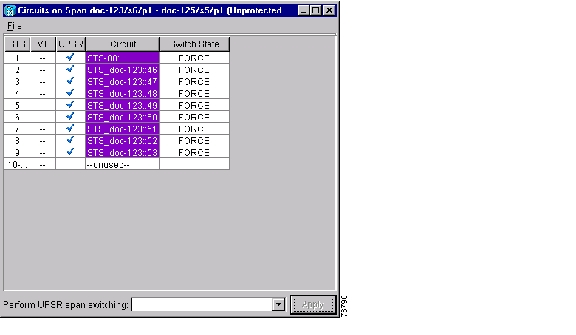
In the Circuits on Span window, the Switch State for all circuits is Force. Figure 13-3 shows an example.

Figure 13-3 Circuits on Span Dialog Box with a Force Switch


Note A Force switch request on a span or card causes CTC to raise a FORCED-REQ condition. The condition clears when you clear the Force switch; it is informational only.


Step 6 Return to your originating procedure (NTP).


DLP-B198 Clear a UPSR Switch

Purpose

Use this task to clear a UPSR Force switch.

Tools/Equipment

None

Prerequisite Procedures

60 Log into CTC

Required/As Needed

As needed

Onsite/Remote

Onsite or remote

Security Level

Provisioning or higher


Step 1 From the View menu, choose Go to Network View.

Step 2 Right-click the span where you want to clear the switch. Choose Circuits from the shortcut menu.

Step 3 In the Circuits on Span dialog box, choose CLEAR to remove the switch. Click Apply.

Step 4 In the Confirm UPSR Switch dialog box, click Yes.

Step 5 In the Protection Switch Result dialog box, click OK.

In the Circuits on Span window, the Switch State for all UPSR circuits is CLEAR.

Step 6 Return to your originating procedure (NTP).


hometocprevnextglossaryfeedbacksearchhelp

Posted: Mon Feb 25 07:23:52 PST 2008
All contents are Copyright © 1992--2008 Cisco Systems, Inc. All rights reserved.
Important Notices and Privacy Statement.