|
|

Table Of Contents
NTP-B199 Locate and View Circuits
DLP-B262 Filter the Display of Circuits
DLP-B229 View Circuits on a Span
NTP-B151 Modify Circuit Characteristics
DLP-B230 Change a Circuit State
DLP-B232 Change Active and Standby Span Color
DLP-B233 Edit UPSR Circuit Path Selectors
NTP-B416 Convert a CTC Circuit to TL1 Cross-Connects
NTP-B417 Upgrade TL1 Cross-Connects to CTC Circuits
NTP-B78 Create a Monitor Circuit
NTP-B79 Create a J1 Path Trace
DLP-B264 Provision Path Trace on Circuit Source and Destination Ports
DLP-B137 Provision Path Trace on OC-N Ports
Manage Circuits
This chapter explains how to manage Cisco ONS 15327 electrical, optical, and Ethernet circuits.
Before You Begin
To create circuits, see "Create Circuits and VT Tunnels."
To clear any alarm or trouble conditions, refer to the Cisco ONS 15327 Troubleshooting Guide.
This section lists the chapter procedures (NTPs). Turn to a procedure for applicable tasks (DLPs).
1.
199 Locate and View Circuits—Complete as needed.
2.
3.
4.
5.
6.
7.
8.
The Cisco Transport Controller Circuits window displays information about circuits to help you manage the circuits, including circuit status and state. Table 8-1 lists the statuses that CTC can report for each circuit.
Circuit state, shown in Table 8-2, is a user-assigned, administrative status that defines whether the circuit is in or out of service. To carry circuit traffic, circuits must have a status of active and a state of in service (IS).
NTP-B199 Locate and View Circuits
Purpose
This procedure provides tasks that you can use to locate and view ONS 15327 circuits.
Tools/Equipment
None
Prerequisite Procedures
Circuit creation procedure(s) in "Create Circuits and VT Tunnels"
Required/As Needed
As needed
Onsite/Remote
Onsite or remote
Security Level
Retrieve or higher
Step 1
Step 2
Step 3
Step 4
Stop. You have completed this procedure.
DLP-B262 Filter the Display of Circuits
Step 1
•
•
•
Step 2
Step 3
a.
b.
•
•
•
•
•
•
•
•
Step 4
Step 5
Step 6
DLP-B131 Search for Circuits
Step 1
•
•
•
Step 2
Step 3
Step 4
Step 5
•
•
•
•
Step 6
Step 7
Step 8
DLP-B229 View Circuits on a Span
Purpose
This task displays circuits routed on an ONS 15327 span.
Tools/Equipment
None
Prerequisite Procedures
Circuits must be created on the span. See "Create Circuits and VT Tunnels"
Required/As Needed
As needed
Onsite/Remote
Onsite or remote
Security Level
Retrieve or higher
Step 1
Step 2
•
•
On the Circuits on Span dialog box, you can view the following information for circuits provisioned on the span:
•
•
•
•
•
Note
Step 3
NTP-B151 Modify Circuit Characteristics
Purpose
This procedure modifies the properties of ONS 15327 circuits.
Tools/Equipment
None
Prerequisite Procedures
Circuits must exist on the network. See "Create Circuits and VT Tunnels" for circuit creation procedures.
Required/As Needed
As needed
Onsite/Remote
Onsite or remote
Security Level
Provisioning or higher
Step 1
Step 2
Step 3
Step 4
Stop. You have completed this procedure.
DLP-B230 Change a Circuit State
Purpose
Use this task to change the state of a circuit.
Tools/Equipment
None
Prerequisite Procedures
Required/As Needed
As needed
Onsite/Remote
Onsite or remote
Security Level
Provisioning or higher
Step 1
Step 2
Note
Step 3
Note
Step 4
•
•
•
•
See Table 8-2 for additional information about circuit states.
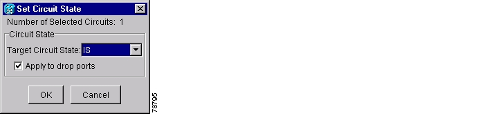
Step 5
Figure 8-1 Changing Circuit State
Step 6
Note
Step 7
DLP-B231 Edit a Circuit Name
Purpose
Use this task to edit a circuit name.
Tools/Equipment
None
Prerequisite Procedures
Required/As Needed
As needed
Onsite/Remote
Onsite or remote
Security Level
Provisioning or higher
Step 1
Step 2
Step 3
Step 4
Step 5
Step 6
Step 7
DLP-B232 Change Active and Standby Span Color
Step 1
Step 2
Step 3
•
•
•
Step 4
a.
b.
c.
Step 5
a.
b.
c.
Step 6
a.
b.
c.
d.
Step 7
DLP-B233 Edit UPSR Circuit Path Selectors
Step 1
Step 2
Step 3
Note
Step 4
•
•
•
•
•
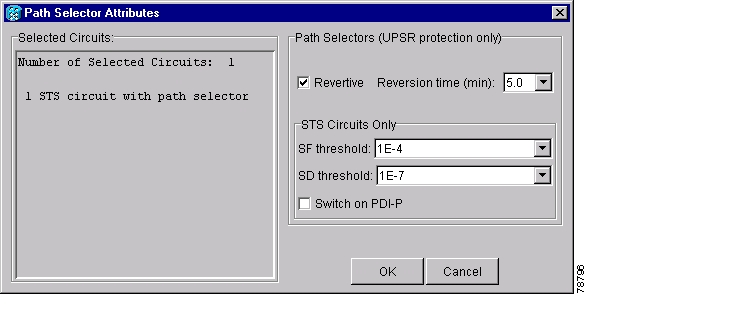
Step 5
Figure 8-2 Editing UPSR Path Selectors
Step 6
NTP-B416 Convert a CTC Circuit to TL1 Cross-Connects
Purpose
Use this procedure to convert CTC circuits to a set of TL1 cross-connects, which enables you to repair a missing cross-connect or change the cross-connect(s) using the TL1-like circuit option during circuit creation.
Tools/Equipment
None
Prerequisite Procedures
Circuits must exist on the network. See "Create Circuits and VT Tunnels" for circuit creation procedures.
Required/As Needed
As needed
Onsite/Remote
Onsite or remote
Security Level
Provisioning or higher
Note
Step 1
Step 2
Step 3
Step 4
Step 5
The Convert to TL1 Cross Connect Results dialog box displays the results of the conversion. If any circuits could not be converted, those circuits are listed.
Step 6
If the circuit you selected had an INCOMPLETE status, its status will not change. If you selected an ACTIVE (complete) circuit, its status will change to UPGRADABLE.
Step 7
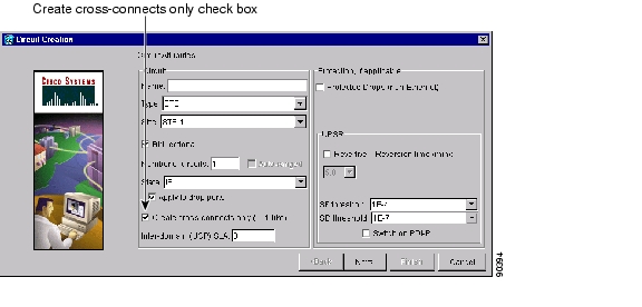
After you repair or replace all missing cross-connects, CTC automatically merges them and the circuit status changes to UPGRADEABLE.
Figure 8-3 Choosing the Cross-Connects Only Option
Step 8
Stop. You have completed this procedure.
NTP-B417 Upgrade TL1 Cross-Connects to CTC Circuits
Purpose
Use this procedure to convert a series of cross-connects displayed as UPGRADABLE in the CTC Circuits window to an ACTIVE CTC circuit.
Tools/Equipment
None
Prerequisite Procedures
TL1-created or CTC-created TL1-like cross-connects must exist on the network. See "Create Circuits and VT Tunnels" for cross-connect creation procedures.
Required/As Needed
As needed
Onsite/Remote
Onsite or remote
Security Level
Provisioning or higher
Step 1
Step 2
Step 3
Step 4
Step 5
The circuit status changes to ACTIVE.
Step 6
Stop. You have completed this procedure.
NTP-B152 Delete Circuits
Purpose
Use this procedure to delete circuits.
Tools/Equipment
None
Prerequisite Procedures
Circuits must exist on the network. See "Create Circuits and VT Tunnels" for circuit creation procedures.
Required/As Needed
As needed
Onsite/Remote
Onsite or remote
Security Level
Provisioning or higher
Step 1
Step 2
Step 3
Step 4
Step 5
Step 6
Step 7
Step 8
Stop. You have completed this procedure.
NTP-B78 Create a Monitor Circuit
Purpose
Use this procedure to create a monitor circuit that monitors traffic on primary, bidirectional circuits.
Tools/Equipment
None
Prerequisite Procedures
Bidirectional (2-way) circuits must exist on the network. See "Create Circuits and VT Tunnels" for circuit creation procedures.
Required/As Needed
As needed
Onsite/Remote
Onsite or remote
Security Level
Provisioning or higher
Note
Note
Step 1
Step 2
Step 3
Step 4
Step 5
Step 6
The Monitors tab displays ports that you can use to monitor the circuit.
Note
Step 7
Step 8
Step 9
Step 10
Step 11
Step 12
Step 13
Stop. You have completed this procedure.
NTP-B79 Create a J1 Path Trace
Purpose
Use this procedure to create a repeated, fixed-length string of characters used to monitor interruptions or changes to circuit traffic.
Tools/Equipment
ONS 15327 cards capable of transmitting and/or receiving path trace must be installed. See Table 8-3 for a list of cards.
Prerequisite Procedures
Path trace can only be provisioned on OC-N (STS) circuits. See "Create Circuits and VT Tunnels" for OC-N circuit creation procedures.
Required/As Needed
As needed
Onsite/Remote
Onsite or remote
Security Level
Provisioning or higher
Step 1
Step 2
•
•
Stop. You have completed this procedure.
DLP-B264 Provision Path Trace on Circuit Source and Destination Ports
Purpose
Use this task to create a path trace on STS circuit source ports and destination ports.
Tools/Equipment
ONS 15327 cards capable of transmitting and receiving path trace must be installed at the circuit source and destination ports. See Table 8-3 for a list of cards.
Prerequisite Procedures
Required/As Needed
As needed
Onsite/Remote
Onsite or remote
Security Level
Provisioning or higher
Note
Step 1
Step 2
Table 8-3 ONS 15327 Cards Capable of Path Trace
Transmit and Receive
XTC (DS-1)
G1000-2
Receive Only
OC3 IR 4 1310
OC12 IR 1310, OC12 LR 1550
OC48 IR 1310, OC48 LR 1550
If neither port is on a transmit/receive card, you will not be able to complete this task. If one port is on a transmit/receive card and the other is on a receive-only card, you can set up the transmit string at the transmit/receive port and the receive string at the receive-only port, but you will not be able to transmit in both directions.
Step 3
Step 4
Step 5
a.
b.
c.
Step 6
a.
b.
c.
Step 7
a.
•
•
b.
c.
Note
d.
Step 8
a.
b.
•
•
c.
d.
Note
e.
Step 9
•
•
•
Caution
The Expect and Receive strings are updated every few seconds if the Path Trace Mode field is set to Auto or Manual.
Step 10
Figure 8-4 Setting Up a Path Trace
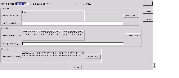
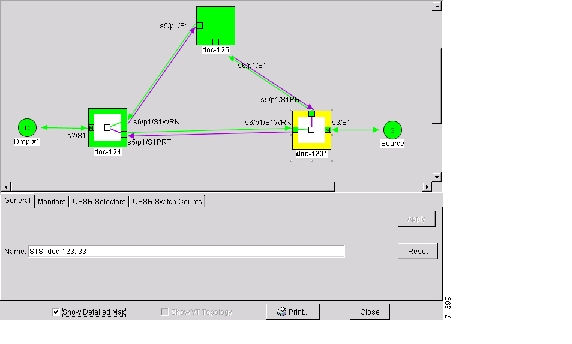
When you display the detailed circuit window, path trace is indicated by an M (manual path trace) or an A (automatic path trace) at the circuit source and destination ports. Figure 8-5 shows an example.
Figure 8-5 Detailed Circuit Window With Manual Expected String Enabled
Step 11
DLP-B137 Provision Path Trace on OC-N Ports
Purpose
Use this task to monitor a path trace on OC-N ports within the circuit path.
Tools/Equipment
The OC-N ports you want to monitor must be on OC-N cards capable of receiving path trace. See Table 8-3.
Prerequisite Procedures
264 Provision Path Trace on Circuit Source and Destination Ports
Required/As Needed
As needed
Onsite/Remote
Onsite or remote
Security Level
Provisioning or higher
Step 1
Step 2
Step 3
Step 4
Step 5
Note
Step 6
•
•
Step 7
Step 8
Step 9
![]()
![]()
![]()
![]()
![]()
![]()
![]()
![]()
Posted: Mon Feb 25 06:23:35 PST 2008
All contents are Copyright © 1992--2008 Cisco Systems, Inc. All rights reserved.
Important Notices and Privacy Statement.