cc/td/doc/product/ong/15327/r34userd
hometocprevnextglossaryfeedbacksearchhelp
PDF

Table Of Contents

Upgrade Cards and Spans

Before You Begin

NTP-B229 Upgrade the XTC-14 Card to XTC-28 Card

NTP-B94 Upgrade Optical Spans Automatically

NTP-B95 Upgrade Optical Spans Manually

DLP-B293 Perform a Manual Span Upgrade on a Two-Fiber BLSR

DLP-B295 Perform a Manual Span Upgrade on a UPSR

DLP-B296 Perform a Manual Span Upgrade on a 1+1 Protection Group

DLP-B297 Perform a Manual Span Upgrade on an Unprotected Span


Upgrade Cards and Spans


This chapter explains how to upgrade the XTC card and how to upgrade optical speeds within a ring or protection group.

Before You Begin

This section lists the chapter procedures (NTPs). Turn to a procedure for applicable tasks (DLPs).

1. 229 Upgrade the XTC-14 Card to XTC-28 Card—Complete this procedure as needed to upgrade the XTC-14 card to the XTC-28 card.

2. 94 Upgrade Optical Spans Automatically—Complete this procedure as needed to upgrade optical cards within UPSRs, BLSRs, and 1+1 protection groups.

3. 95 Upgrade Optical Spans Manually—Complete this procedure as needed to perform error recovery for the Span Upgrade Wizard or back out of a span upgrade (downgrade).

NTP-B229 Upgrade the XTC-14 Card to XTC-28 Card

Purpose

This procedure upgrades the XTC-14 card to the XTC-28 card. The procedure is non-service affecting; the upgrade will cause a protection switch of less than 50 ms in duration.

Tools/Equipment

Two XTC-28 cards

Prerequisite Procedures

None

Required/As Needed

As needed

Onsite/Remote

Onsite

Security Level

None


Note The UNEQ-P alarm might be raised during the upgrade if you have E10/E100-4 cards in the node. The alarm will appear and clear within a few seconds.


Note The MEA (card mismatch) alarm appears because CTC recognizes a mismatch between XTC card types. Disregard this alarm; it clears by the end of the procedure.


Step 1 Complete the "NTP-B108 Back Up the Database" procedure on page 14-6 before beginning the upgrade.

Step 2 Determine which XTC-14 card is the standby card. An amber ACT/STBY LED on the card faceplate indicates a standby card.

Step 3 Physically replace the standby XTC-14 card on the ONS 15327 with an XTC-28 card:

a. Open the XTC-14 card ejector.

b. Slide the card out of the slot. This raises an IMPROPRMVL alarm which will clear when the upgrade is complete. Ensure that traffic is flowing over the 14 DS-1 ports. Abnormal alarms will indicate if there is a problem with traffic. Ensure that the alarm filter is not selected when you are checking for abnormal alarms.

c. Open the ejector on the XTC-28 card.

d. Slide the XTC-28 card into the slot along the guide rails.

e. Close the ejector and secure the screw.

f. The ONS 15327 boots up the XTC-28 card. The XTC-28 card must copy the database, which can take approximately 10 minutes. Do not remove the card from the shelf during a database transfer.


Note The LEDs will flash while the XTC-28 is loading.


Step 4 After the XTC-28 has finished synchronizing its software and database and is in standby mode, in node view right-click the active XTC-14 and choose Reset from the drop-down menu ( Figure 11-1).

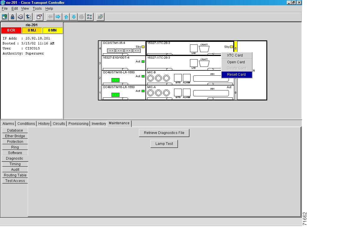
Figure 11-1 Resetting the XTC card

Step 5 Physically replace the remaining XTC-14 card:

a. Open the XTC-14 card ejector.

b. Slide the card out of the slot. This raises an IMPROPRMVL alarm that will clear when the upgrade is complete.

c. Open the ejector on the XTC-28 card.

d. Slide the XTC-28 card into the slot along the guide rails.

e. Close the ejector and secure the screw.

f. The ONS 15327 boots up the second XTC-28 card. The second XTC-28 card must also copy the database, which can take approximately 10 minutes. Do not remove the card from the shelf during a database transfer.

Step 6 If power-related alarms occur after the second XTC-28 card is installed, check the voltage on the backplane. See the "DLP-B33 Measure Voltage" task on page 1-49 for instructions. Refer to the Cisco ONS 15327 Troubleshooting Guide for information on clearing alarms.

Stop. You have completed this procedure.


NTP-B94 Upgrade Optical Spans Automatically

Purpose

This procedure upgrades OC-N speeds within BLSRs, UPSRs, and 1+1 protection groups using the Span Upgrade Wizard. Upgrading a span is non-service affecting and will cause no more than three switches, each of which is less than 50 ms in duration.

Tools/Equipment

Replacement cards

Prerequisite Procedures

The span upgrade procedure requires at least two technicians (one at each end of the span) who can communicate with each other during the upgrade.

Required/As Needed

As needed

Onsite/Remote

Onsite

Security Level

Provisioning or higher


Warning Do not reach into a vacant slot or chassis while you install or remove a module or a fan. Exposed circuitry could constitute an energy hazard.


Caution Do not perform any other maintenance operations or add any circuits during a span upgrade.


Note The Span Upgrade option will only be visible and available if the hardware necessary for the upgrade is present.


Step 1 Complete the "DLP-B60 Log into CTC" task. If you are already logged in, continue with Step 2.

Step 2 Ensure that no alarms or abnormal conditions (regardless of severity), including LOS, LOF, AIS-L, SF, SD, and FORCED-REQ-RING are present. See the "DLP-B298 Check the Network for Alarms and Conditions" task for instructions.

Step 3 In network view, right-click the span you want to upgrade.

Step 4 Choose Span Upgrade from the drop-down menu.

Step 5 The first Span Upgrade dialog box appears. Follow the instructions on the dialog box and the wizard will lead you through the rest of the span upgrade.


Caution As indicated by the wizard, when installing cards you must wait for the cards to boot up and become active before proceeding to the next step.


Note The Back button is only enabled in the first screen of the wizard; because you cannot back out of an upgrade via the wizard, close the wizard and initiate the manual procedure if you need to back out of the upgrade at any point beyond the second screen.


Note Remember to attach the fiber after installing the OC-N cards.


Step 6 Repeat Steps 2 through 5 for additional spans in the ring.


Note Optical transmit and receive levels should be in their acceptable range as shown in the specifications section for each card in the Cisco ONS 15327 Reference Manual.


Note The span upgrade process resets the line CV-L threshold to the factory default. The CV-L threshold is reset because the threshold is dependent on line rate.


Note Span upgrades do not upgrade SONET topologies; for example, 1+1 protection group to a two-fiber BLSR.


Note During the upgrade/downgrade some minor alarms and conditions display and then clear automatically. No service-affecting alarms (SA, Major, or Critical) should occur other than BLSR Out of Sync, which will clear when the upgrade/downgrade of all nodes is complete. If any other service-affecting alarms occur, Cisco recommends backing out of the procedure.
Extra time may be required to clear all of the Out of Sync alarms depending on the size of the BLSR.


Stop. You have completed this procedure.


NTP-B95 Upgrade Optical Spans Manually

Purpose

This procedure upgrades OC-N speeds within BLSRs, UPSRs, and 1+1 protection groups by upgrading OC-N cards. Upgrading a span is non-service affecting and will cause no more than three switches, each of which is less than 50 ms in duration.

Tools/Equipment

Replacement cards

Prerequisite Procedures

The manual span upgrade procedure requires at least two technicians (one at each end of the span) who can communicate with each other during the upgrade.

Required/As Needed

As needed

Onsite/Remote

Onsite

Security Level

Provisioning or higher


Note Optical card transmit and receive levels should be in their acceptable range as shown in the specifications section for each card in the Cisco ONS 15327 Reference Manual.


Note In this context the word "span" represents the optical path between two nodes. The words "span endpoint" represent the nodes on each end of a span.


Note If any of the XTC cards reboot during the span upgrade, you must manually reset each one when the span upgrade procedure is complete for all the nodes in the ring. See the "NTP-B113 Reset the XTC Using CTC" procedure on page 14-23 for card reset procedures.


Step 1 Determine the type of span you need to upgrade and make sure you have the necessary cards. Valid span upgrades include:

OC-12 to OC-48

OC-12 IR to OC-12 LR

OC-48 IR to OC-48 LR

Step 2 Complete the "DLP-B60 Log into CTC" task. The node (default) view appears. If you are already logged in, continue with Step 3.

Step 3 Ensure that no alarms or abnormal conditions (regardless of severity), including LOS, LOF, AIS-L, SF, SD, and FORCED-REQ-RING are present. See the "DLP-B298 Check the Network for Alarms and Conditions" task for instructions.


Note During the upgrade/downgrade some minor alarms and conditions display and then clear automatically. No service-affecting alarms (SA, Major, or Critical) should occur other than BLSR Out-of-Sync, which will clear when the upgrade/downgrade of all nodes is complete. If any other service-affecting alarms occur, Cisco recommends backing out of the procedure.
Allow extra time for a large BLSR to clear all of the Out-of-Sync alarms.


Step 4 Complete a manual upgrade task if you need to perform error recovery for the Span Upgrade Wizard or back out of a span upgrade (downgrade):

Complete the "DLP-B293 Perform a Manual Span Upgrade on a Two-Fiber BLSR" task to upgrade an optical span manually within a two-fiber BLSR.

Complete the "DLP-B295 Perform a Manual Span Upgrade on a UPSR" task to upgrade an optical span manually within a UPSR.

Complete the "DLP-B296 Perform a Manual Span Upgrade on a 1+1 Protection Group" task to upgrade an optical span manually within a 1+1 protection group.

Complete the "DLP-B297 Perform a Manual Span Upgrade on an Unprotected Span" task to upgrade an unprotected optical span manually.


Note The span upgrade process resets the line's CV-L threshold to factory default. The CV-L threshold is reset because the threshold is dependent on line rate.


Note Span upgrades do not upgrade SONET topologies; for example, 1+1 protection group to a two-fiber BLSR.


Note The Span Upgrade option will only be visible and available if the hardware necessary for the upgrade is present.


Stop. You have completed this procedure.


DLP-B293 Perform a Manual Span Upgrade on a Two-Fiber BLSR

Purpose

This task upgrades a two-fiber BLSR span to a higher optical rate.

Tools/Equipment

Higher-rate cards

Compatible hardware necessary for the upgrade

Prerequisite Procedures

60 Log into CTC

Required/As Needed

As needed

Onsite/Remote

Onsite

Security Level

Provisioning or higher


Warning Do not reach into a vacant slot or chassis while you install or remove a module or a fan. Exposed circuitry could constitute an energy hazard.


Caution Do not perform any other maintenance operations or add any circuits during a span upgrade.


Note If any of the XTC cards reboot during the span upgrade, you must manually reset each one when the span upgrade procedure is complete for all the nodes in the ring. See the "NTP-B113 Reset the XTC Using CTC" procedure on page 14-23 for card reset procedures.


Note All spans connecting the nodes in a BLSR must be upgraded before the bandwidth is available.


Step 1 Ensure that no alarms or abnormal conditions (regardless of severity), including LOS, LOF, AIS-L, SF, SD, and FORCED-REQ-RING are present on the BLSR that you will upgrade. See the "DLP-B298 Check the Network for Alarms and Conditions" task for instructions.

Step 2 Apply a Force switch to both span endpoints (nodes) on the span that you will upgrade first. See "DLP-B303 Initiate a BLSR Force Ring Switch" task.

Step 3 Remove the fiber from both endpoints and ensure that traffic is still running.

Step 4 Remove the OC-N cards from both endpoints.

Step 5 At one endpoint, in node view right-click the OC-N card and choose Change Card.

Step 6 In the Change Card dialog box, choose the new OC-N card type.

Step 7 Click OK.

Step 8 Repeat Steps 5 through 7 at the second endpoint.

Step 9 Install the new OC-N cards in both endpoints before attaching the fiber to the newly installed OC-N cards. Check that the receive signal falls within the acceptable range. Wait for the IMPROPRMVL alarm to clear and the cards to become active.

Step 10 When cards in both endpoint nodes have been successfully upgraded and all facility alarms (LOS, SD or SF) are cleared, complete the "DLP-B194 Clear a BLSR Force Ring Switch" task at both endpoints.

The Force switch clears and traffic is running. If you have lost traffic, make sure the cabling is installed properly. See the "NTP-B221 Install Optical Cables" procedure on page 1-40. If this does not resolve the problem, perform a downgrade. The procedure for downgrading is the same as upgrading except that you choose a lower-rate card in Step 6 and install a lower-rate card in Step 9.

Step 11 Repeat this task for each span in the BLSR. When you are done with each span, the upgrade is complete.

Step 12 Return to your originating procedure (NTP).


DLP-B295 Perform a Manual Span Upgrade on a UPSR

Purpose

This task upgrades UPSR spans to a higher optical speed. Repeat the task to upgrade each span, and thus the entire ring, to the higher optical rate.

Tools/Equipment

Higher-rate cards

Compatible hardware necessary for the upgrade

Prerequisite Procedures

60 Log into CTC

Required/As Needed

As needed

Onsite/Remote

Onsite

Security Level

Provisioning or higher


Warning Do not reach into a vacant slot or chassis while you install or remove a module or a fan. Exposed circuitry could constitute an energy hazard.


Caution Do not perform any other maintenance operations or add any circuits during a span upgrade.


Note If any of the XTC cards reboot during the span upgrade, you must manually reset each one, once the span upgrade procedure is complete for all the nodes in the ring. See the "NTP-B113 Reset the XTC Using CTC" procedure on page 14-23 for card reset procedures.


Step 1 Ensure that no alarms or abnormal conditions (regardless of severity), including LOS, LOF, AIS-L, SF, SD, and FORCED-REQ-RING are present on the span that you will upgrade. See the "DLP-B298 Check the Network for Alarms and Conditions" task for instructions.

Step 2 Complete the "DLP-B197 Initiate a UPSR Force Switch" task on the span that you will upgrade at both endpoints.

Step 3 Remove the fiber from both endpoint nodes in the span and ensure that traffic is still running.

Step 4 Remove the OC-N cards from both span endpoints.

Step 5 At one endpoint, in node view right-click the OC-N card and choose Change Card.

Step 6 In the Change Card dialog box, choose the new OC-N card type.

Step 7 Click OK.

Step 8 Before attaching the fiber to the newly installed OC-N cards, check that the receive signal falls within the acceptable range. Install the new OC-N cards in both endpoints and attach the fiber to the cards. Wait for the IMPROPRMVL alarm to clear and the cards to become active.

Step 9 Complete the "DLP-B198 Clear a UPSR Switch" task at both endpoints when cards in both nodes have been successfully upgraded and all the facility alarms (LOS, SD or SF) are cleared.

The Force switch clears and traffic is running. If you have lost traffic, make sure the cabling is installed properly. See the "NTP-B221 Install Optical Cables" procedure on page 1-40. If this does not resolve the problem, perform a downgrade. The procedure for downgrading is the same as upgrading except that you choose a lower-rate card in Step 6 and install a lower-rate card in Step 8.

Step 10 Return to your originating procedure (NTP).


DLP-B296 Perform a Manual Span Upgrade on a 1+1 Protection Group

Purpose

This task upgrades a linear 1 + 1 span to a higher optical rate.

Tools/Equipment

Higher-rate cards

Compatible hardware necessary for the upgrade

Prerequisite Procedures

60 Log into CTC

Required/As Needed

As needed

Onsite/Remote

Onsite

Security Level

Provisioning or higher


Warning Do not reach into a vacant slot or chassis while you install or remove a module or a fan. Exposed circuitry could constitute an energy hazard.


Caution Do not perform any other maintenance operations or add any circuits during a span upgrade.


Note If any of the XTC cards reboot during the span upgrade, you must manually reset each one when the span upgrade procedure is complete for all the nodes in the ring. See the "NTP-B113 Reset the XTC Using CTC" procedure on page 14-23 for card reset procedures.


Step 1 Ensure that no alarms or abnormal conditions (regardless of severity), including LOS, LOF, AIS-L, SF, SD, and FORCED-REQ-RING are present on the span that you will upgrade. See the "DLP-B298 Check the Network for Alarms and Conditions" task for instructions.

Step 2 Apply a Force switch on the ports that you will upgrade, beginning with the protect port:

a. In node view, click the Maintenance > Protection tabs.

b. Under Protection Groups, choose the 1+1 protection group.

c. Under Selected Group, choose the protect port (regardless if it is active or standby).

d. From Switch Commands, click Force.

e. Click Yes on the confirmation dialog box.


Note If the switching mode is bidirectional in the 1+1 protection group, apply the Force command to only one end of the span. If the Force command is applied to both ends when the switching mode is bidirectional, a switch of more than 50 ms in duration will result.


Note A Force switch request on a span or card (port) causes CTC to raise a FORCED-REQ condition. It is informational only; the condition will clear when the force switch command is cleared.


Step 3 Repeat Step 2 for each port you will upgrade.

Step 4 Remove the fiber from both ends of the span and ensure that traffic is still running.

Step 5 Remove the OC-N cards from both span endpoints.

Step 6 At one endpoint, in node view, right-click the OC-N slot and choose Change Card.

Step 7 In the Change Card dialog box, choose the new OC-N card type.

Step 8 Click OK.

Step 9 Repeat Steps 5 through 7 at the second endpoint.

Step 10 Install the new OC-N cards in both endpoints before attaching the fiber to the newly installed OC-N cards, check that the receive signal falls within the acceptable range. Wait for the IMPROPRMVL alarm to clear and the cards to become standby.

Step 11 When cards on each end of the span have been successfully upgraded and all the facility alarms (LOS, SD or SF) are cleared, remove the Force switch:

a. In node view, click the Maintenance > Protection tabs.

b. Under Protection Groups, choose the 1+1 protection group.

c. Under Selected Group, choose the port with the force on it.

d. From Switch Commands, click Clear.

e. Click Yes on the confirmation dialog box.

The Force switch clears and traffic is running. If you have lost traffic, make sure the cabling is installed properly. See the "NTP-B221 Install Optical Cables" procedure on page 1-40. If this does not resolve the problem, perform a downgrade. The procedure for downgrading is the same as upgrading except that you choose a lower-rate card in Step 7 and install a lower-rate card in Step 9.

Step 12 Repeat this task for any other spans in the 1 + 1 linear configuration.

Step 13 Return to your originating procedure (NTP).


DLP-B297 Perform a Manual Span Upgrade on an Unprotected Span

Purpose

This task manually upgrades unprotected spans to a higher optical rate.

Tools/Equipment

Higher-rate cards

Compatible hardware necessary for the upgrade

Prerequisite Procedures

60 Log into CTC

Required/As Needed

As needed

Onsite/Remote

Onsite

Security Level

Provisioning or higher


Warning Do not reach into a vacant slot or chassis while you install or remove a module or a fan. Exposed circuitry could constitute an energy hazard.


Caution Upgrading unprotected spans will cause all traffic running on those spans to be lost.


Caution Do not perform any other maintenance operations or add any circuits during a span upgrade.


Note If any of the XTC cards reboot during the span upgrade, you must manually reset each one when the span upgrade procedure is complete for all the nodes in the ring. See the "NTP-B113 Reset the XTC Using CTC" procedure on page 14-23 for card reset procedures.


Step 1 Ensure that no alarms or abnormal conditions (regardless of severity), including LOS, LOF, AIS-L, SF, and SD, are present on the span that you will upgrade. See the "DLP-B298 Check the Network for Alarms and Conditions" task for instructions.

Step 2 Remove the fiber from both endpoint nodes in the span.


Caution Removing the fiber will cause all traffic on the unprotected span to be lost.

Step 3 Remove the OC-N cards from both span endpoints.

Step 4 At one endpoint, in node view, right-click each OC-N slot and choose Change Card.

Step 5 In the Change Card dialog box, choose the new OC-N type.

Step 6 Click OK.

Step 7 Repeat Steps 4 through 6 at the second endpoint.

Step 8 Install the new OC-N cards in both endpoints and attach the fiber to the cards. Wait for the IMPROPRMVL alarm to clear and the cards to become active.

Step 9 Return to your originating procedure (NTP).


hometocprevnextglossaryfeedbacksearchhelp

Posted: Mon Feb 25 06:37:15 PST 2008
All contents are Copyright © 1992--2008 Cisco Systems, Inc. All rights reserved.
Important Notices and Privacy Statement.