|
|

Table Of Contents
NTP-B107 Inspect and Maintain the Air Filter
DLP-B199 Inspect, Clean, and Replace the Reusable Air Filter
DLP-B200 Inspect and Replace the Disposable Air Filter
NTP-B163 Restore the Node to Factory Configuration
DLP-B244 Use the Reinitialization Tool to Clear the Database and Upload Software (Windows)
DLP-B245 Use the Reinitialization Tool to Clear the Database and Upload Software (UNIX)
NTP-B214 Offload the Security Audit Trail Log
NTP-B110 Inhibit Protection Switching
DLP-B203 Clear a Lock On or Lock Out
NTP-B111 Revert to an Earlier Software Load
NTP-B112 Clean Fiber Connectors
DLP-B204 Scope and Clean Fiber Connectors and Adapters with Alcohol and Dry Wipes
DLP-B205 Clean Fiber Connectors with CLETOP
DLP-B206 Clean the Fiber Adapters
NTP-B113 Reset the XTC Using CTC
NTP-B215 View G1000-2 Ethernet Maintenance Information
DLP-B307 View Ethernet Bandwidth Usage
NTP-B228 View E10/100-4 Ethernet Maintenance Information
DLP-B309 View Ethernet MAC Address Table
DLP-B310 View Ethernet Trunk Utilization
NTP-B225 Switch the Node Timing Reference
DLP-B330 Manual or Force Switch the Node Timing Reference
DLP-B331 Clear a Manual or Force Switched Node Timing Reference
Maintain the Node
This chapter provides procedures for maintaining the Cisco ONS 15327.
Before You Begin
Before performing any of the following procedures, investigate all alarms and clear any trouble conditions. Refer to the Cisco ONS 15327 Troubleshooting Guide as necessary. This section lists the chapter procedures (NTPs). Turn to a procedure to view its tasks (DLPs).
1.
107 Inspect and Maintain the Air Filter—Complete as needed.
2.
3.
4.
5.
6.
7.
8.
9.
10.
11.
12.
NTP-B107 Inspect and Maintain the Air Filter
Warning
Note
Step 1
Step 2
Stop. You have completed this procedure.
DLP-B199 Inspect, Clean, and Replace the Reusable Air Filter
Warning
Step 1
Step 2
Step 3
Figure 14-1 Removing the Reusable Fan-Tray Air Filter
Step 4
Step 5
Step 6
Note
Warning
Step 7
Figure 14-2 Replacing the Reusable Fan-Tray Air Filter
Step 8
DLP-B200 Inspect and Replace the Disposable Air Filter
Note
Step 1
Step 2
Step 3
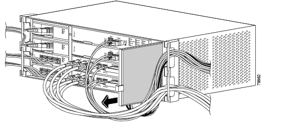
Figure 14-3 Removing the Disposable Fan-Tray Air Filter
Step 4
Step 5
Step 6
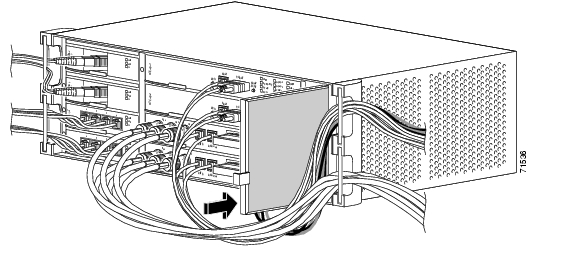
Figure 14-4 Replacing the Disposable Fan-Tray Air Filter
Step 7
NTP-B108 Back Up the Database
Note
Note
Step 1
Step 2
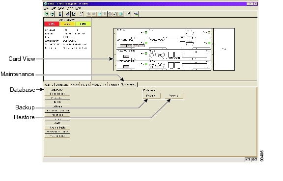
Figure 14-5 Backing Up the XTC Database
Step 3
Step 4
Step 5
Step 6
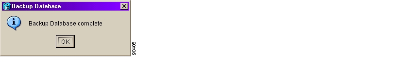
Figure 14-6 Confirming the Database Backup
Stop. You have completed this procedure.
NTP-B109 Restore the Database
Purpose
This procedure restores the software database.
Tools/Equipment
None
Prerequisite Procedures
Required/As Needed
As needed
Onsite/Remote
Onsite or remote
Security Level
Superuser
Note
Caution
Caution
Step 1
Step 2
a.
b.
Step 3
Figure 14-7 Restoring the XTC Database
Step 4
Step 5
Note
Step 6
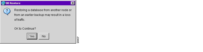
Step 7
Figure 14-8 Restoring the Database—Traffic Loss Warning
Step 8
The Restore Database dialog box monitors the file transfer ( Figure 14-9).
Figure 14-9 Restoring the Database—In-Process Notification
Step 9
Step 10
Step 11
Stop. You have completed this procedure.
NTP-B163 Restore the Node to Factory Configuration
Caution
Caution
Note
Step 1
Step 2
Step 3
Stop. You have completed this procedure.
DLP-B244 Use the Reinitialization Tool to Clear the Database and Upload Software (Windows)
Note
Step 1
Step 2
Step 3
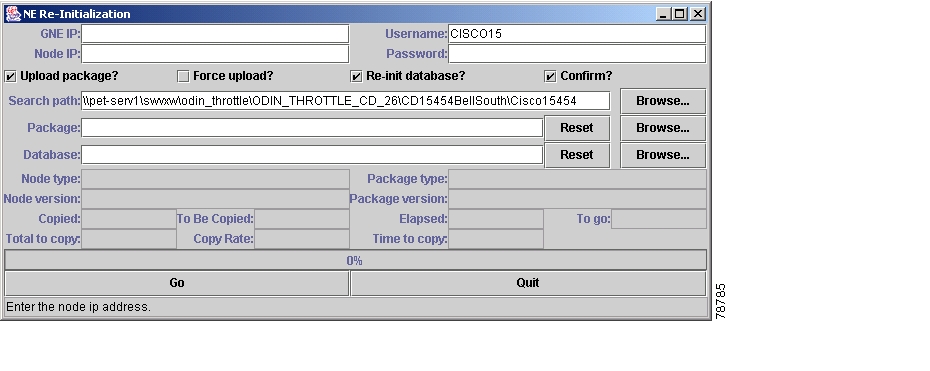
Step 4
Figure 14-10 Reinitialization Tool in Windows
Step 5
Step 6
Step 7
Step 8
Caution
Caution
Step 9
Step 10
Step 11
Note
Step 12
Step 13
Figure 14-11 Confirm NE Restoration
Step 14
DLP-B245 Use the Reinitialization Tool to Clear the Database and Upload Software (UNIX)
Note
Step 1
Step 2
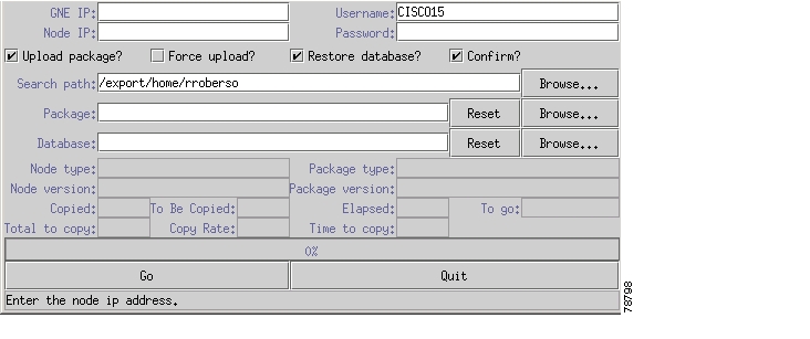
Step 3
Figure 14-12 Reinitialization Tool in UNIX
Step 4
Step 5
Step 6
Step 7
Caution
Caution
Step 8
Step 9
Step 10
Note
Step 11
Step 12
Step 13
NTP-B214 Offload the Security Audit Trail Log
Step 1
Step 2
Step 3
Step 4
Step 5
Step 6
You do not have to give the archive file a particular extension. It is readable in any application that supports text files, such as WordPad, Microsoft Word (imported), etc.
Step 7
Up to 640 entries will be saved in this file. The next entries will continue with the next number in the sequence, rather than starting over.
Note
Stop. You have completed this procedure.
NTP-B110 Inhibit Protection Switching
Purpose
This procedure describes how to apply and remove a lock on or lock out on a traffic card in a protection configuration. For bidirectional line switch ring (BLSR) span lockouts, see the "DLP-B301 Initiate a BLSR Manual Ring Switch" task and the "DLP-B241 Clear a BLSR Manual Ring Switch" task.
Tools/Equipment
None
Prerequisite Procedures
None
Required/As Needed
As needed
Onsite/Remote
Onsite
Security Level
Superuser
Step 1
Step 2
Note
Step 3
Note
Note
Stop. You have completed this procedure.
DLP-B201 Apply a Lock On
Note
Step 1
•
•
Step 2
Step 3
Step 4
a.
b.
Step 5
Step 6
Step 7
The lock on has been applied and traffic cannot be switched to the working card. To clear the lock on, see the "DLP-B203 Clear a Lock On or Lock Out" task.
Step 8
DLP-B202 Apply a Lock Out
Note
Step 1
•
•
Step 2
Step 3
Step 4
Step 5
Step 6
The lock out has been applied and traffic is switched to the opposite card. To clear the lock out, see the "DLP-B203 Clear a Lock On or Lock Out" task.
Note
Step 7
DLP-B203 Clear a Lock On or Lock Out
Purpose
This task clears a lock on or lock out.
Tools/Equipment
None
Prerequisite Procedures
Required/As Needed
As needed
Onsite/Remote
Onsite or remote
Security Level
Maintenance
Step 1
Step 2
Step 3
Step 4
Step 5
The lock on or lock out is cleared.
Step 6
NTP-B111 Revert to an Earlier Software Load
Tip
Note
Step 1
Step 2
•
•
Step 3
Step 4
Step 5
Step 6
Step 7
Step 8
Step 9
Step 10
Step 11
"DLP-B60 Log into CTC" task as necessary.The browser downloads the CTC applet for the standby software load.
Step 12
Stop. You have completed this procedure.
NTP-B112 Clean Fiber Connectors
Warning
Step 1
Step 2
Note
Step 3
Step 4
Step 5
Caution
Stop. You have completed this procedure.
DLP-B204 Scope and Clean Fiber Connectors and Adapters with Alcohol and Dry Wipes
Warning
Step 1
Step 2
Step 3
Step 4
Step 5
Note
Step 6
DLP-B205 Clean Fiber Connectors with CLETOP
Step 1
Step 2
Step 3
Step 4
Step 5
Note
Step 6
DLP-B206 Clean the Fiber Adapters
Purpose
This task cleans the fiber adapters.
Tools/Equipment
CLETOP stick swab
Prerequisite Procedures
None
Required/As Needed
Required
Onsite/Remote
Onsite
Security Level
Maintenance
Step 1
Step 2
Step 3
Step 4
NTP-B113 Reset the XTC Using CTC
Warning
Note
Note
Step 1
Step 2
Step 3
Step 4
Step 5
Note
Step 6
•
•
Stop. You have completed this procedure.
NTP-B215 View G1000-2 Ethernet Maintenance Information
Purpose
This procedure enables viewing the maintenance information on a selected G1000-2 Ethernet card.
Tools/Equipment
None
Prerequisite Procedures
Before you view performance monitoring (PM) values, be sure you have created the appropriate circuits and provisioned the card according to your specifications. For more information, see "Create Circuits and VT Tunnels" and "Change Port Settings."
Required/As Needed
As needed
Onsite/Remote
Onsite or remote
Security Level
Retrieve or higher
Step 1
Step 2
•
•
Stop. You have completed this procedure.
DLP-B306 View Loopback Status
Step 1
Step 2
Step 3
The # and State columns identify the port number and current operating state (IS, OOS, OOS_MT) of each port on the card. The Loopback Type column identifies the type of loopback (None or Terminal) applied to each port on the card.
Step 4
DLP-B307 View Ethernet Bandwidth Usage
Step 1
Step 2
Step 3
The current STS bandwidth usage information appears.
Step 4
NTP-B228 View E10/100-4 Ethernet Maintenance Information
Purpose
This procedure enables viewing the maintenance information on a selected E10/100-4 Ethernet card.
Tools/Equipment
None
Prerequisite Procedures
Before you view PM values, be sure you have created the appropriate circuits and provisioned the card according to your specifications. For more information, see "Create Circuits and VT Tunnels" and "Change Port Settings."
Required/As Needed
As needed
Onsite/Remote
Onsite or remote
Security Level
Retrieve or higher
Step 1
Step 2
Step 3
•
•
Stop. You have completed this procedure.
DLP-B309 View Ethernet MAC Address Table
Step 1
Step 2
Step 3
The MAC address table information is displayed.
Step 4
DLP-B310 View Ethernet Trunk Utilization
Step 1
Step 2
Step 3
The trunk utilization information for the current and previous time intervals is displayed.
Step 4
NTP-B225 Switch the Node Timing Reference
Step 1
Step 2
•
•
Stop. You have completed this procedure.
DLP-B330 Manual or Force Switch the Node Timing Reference
Step 1
Step 2
Step 3
•
•
Step 4
Step 5
•
•
Step 6
DLP-B331 Clear a Manual or Force Switched Node Timing Reference
Step 1
Step 2
Step 3
Step 4
Step 5
•
•
Step 6
![]()
![]()
![]()
![]()
![]()
![]()
![]()
![]()
Posted: Mon Feb 25 06:30:34 PST 2008
All contents are Copyright © 1992--2008 Cisco Systems, Inc. All rights reserved.
Important Notices and Privacy Statement.