cc/td/doc/product/ong/15327/r34userd
hometocprevnextglossaryfeedbacksearchhelp
PDF

Table Of Contents

Turn Up Node

Before You Begin

NTP-B24 Verify Card Installation

NTP-B30 Create Users and Assign Security

DLP-B74 Create a New User - Single Node

DLP-B75 Create a New User - Multiple Nodes

NTP-B25 Set Up Name, Date, Time, and Contact Information

NTP-B169 Set Up CTC Network Access

DLP-B249 Provision IP Settings

DLP-B65 Create a Static Route

DLP-B250 Set Up or Change Open Shortest Path First Protocol

DLP-B251 Set Up or Change Routing Information Protocol

NTP-B27 Set Up the ONS 15327 for Firewall Access

DLP-B67 Provision the IIOP Listener Port on the ONS 15327

DLP-B68 Provision the IIOP Listener Port on the CTC Computer

NTP-B28 Set Up Timing

DLP-B69 Set Up External or Line Timing

DLP-B70 Set Up Internal Timing

NTP-B170 Create Optical Protection Groups

NTP-B171 Set Up SNMP

NTP-B34 Create Ethernet RMON Alarm Thresholds


Turn Up Node


This chapter explains how to provision a single Cisco ONS 15327 node and turn it up for service, including assigning a node name, date and time, SONET timing references, network attributes such as IP address and default router, users and user security, and card protection groups.

Before You Begin

Complete the procedures applicable to your site plan from the following chapters:

Chapter 1, "Install Hardware"

"Connect the PC and Log into the GUI"

This section lists the chapter procedures (NTPs). Turn to a procedure for applicable tasks (DLPs).

1. 24 Verify Card Installation—Complete this procedure first.

2. 30 Create Users and Assign Security—Complete this procedure to create CTC users and assign their security levels.

3. 25 Set Up Name, Date, Time, and Contact Information—Continue with this procedure to set the node name, date, time, location, and contact information.

4. 169 Set Up CTC Network Access—Continue with this procedure to provision the IP address, default router, subnet mask, and network configuration settings.

5. 27 Set Up the ONS 15327 for Firewall Access—Continue with this procedure if the ONS 15327 will be accessed behind firewalls.

6. 28 Set Up Timing—Continue with this procedure to set up the node's SONET timing references.

7. 170 Create Optical Protection Groups—Complete this procedure, as needed, to set up optical protection groups for ONS 15327 cards.

8. 171 Set Up SNMP—Complete this procedure if SNMP will be used for network monitoring.

NTP-B24 Verify Card Installation

Purpose

This procedure verifies that the ONS 15327 node is ready for turn up.

Tools/Equipment

An engineering work order, site plan, or other document specifying the ONS 15327 card installation

Prerequisite Procedures

Chapter 1, "Install Hardware"

Required/As Needed

Required

Onsite/Remote

Onsite

Security Level

Retrieve or higher


Step 1 Verify that two XTC are installed.

Step 2 Verify that the green ACT (active) LED is illuminated on one XTC and the amber STBY (standby) LED is illuminated on the second XTC.


Note If the XTCs are not installed, or their LEDs are not illuminated as described, do not proceed. Repeat the "NTP-B217 Install the XTCs" procedure on page 1-21, or refer to the Cisco ONS 15327 Troubleshooting Guide to resolve installation problems before proceeding to Step 3.


Step 3 Verify that OC-N cards (OC-3, OC-12, and OC-48) and Ethernet cards (E10/100 and G1000-2), if required, are installed in the slots designated by your site plan.

Step 4 Verify that all installed OC-N and Ethernet cards display a solid green ACT LED.

Step 5 Verify that fiber-optic cables are installed and connected to the locations indicated in the site plan. If the fiber-optic cables are not installed, complete the "NTP-B221 Install Optical Cables" procedure on page 1-40.

Step 6 Verify that fiber is routed correctly in the shelf assembly. If the fiber is not routed on the shelf assembly, complete the "DLP-B46 Route Fiber-Optic Cables" task on page 1-47.

Step 7 Continue with the "25 Set Up Name, Date, Time, and Contact Information" procedure.

Stop. You have completed this procedure.


NTP-B30 Create Users and Assign Security

Purpose

This procedure creates ONS 15327 users and assigns their security levels.

Tools/Equipment

None

Prerequisite Procedures

24 Verify Card Installation

Required/As Needed

As needed

Onsite/Remote

Onsite or remote

Security Level

Superuser only


Step 1 Complete the "DLP-B60 Log into CTC" task at the node where you need to create users. If you are already logged in, continue with Step 2.


Note You must log in as a Superuser to create additional users. The CISCO15 user provided with each ONS 15327 can be used to set up other ONS 15327 users. You can add up to 500 users to one ONS 15327.


Step 2 Complete the "DLP-B74 Create a New User - Single Node" task or the "DLP-B75 Create a New User - Multiple Nodes" task as needed.


Note You must add the same user name and password to each node a user will access.


Step 3 If you want to modify the security policy settings, complete the "205 Modify Users and Change Security" procedure.

Stop. You have completed this procedure.


DLP-B74 Create a New User - Single Node

Purpose

This task creates a new user for one ONS 15327.

Tools/Equipment

None

Prerequisite Procedures

60 Log into CTC

Required/As Needed

As needed

Onsite/Remote

Onsite or remote

Security Level

Superuser only


Step 1 In node view, click the Provisioning > Security > Users tabs.

Step 2 In the Security window, click Create.

Step 3 In the Create User dialog box, enter the following:

Name—Type the user name. The name must have a minimum of six and a maximum of 20 alphanumeric characters (a-z, A-Z, 0-9). For TL1 compatibility, the user name must have 6 to 10 characters, and the first character must be an alpha character.

Password—Type the user password. The password must be a minimum of six and a maximum of 20 alphanumeric (a-z, A-Z, 0-9) and special characters (+, #,%), where at least two characters are non-alphabetic and at least one character is a special character. For TL1 compatibility, the password must have 6 to 10 characters, and the first character must be an alpha character. The password cannot contain the user name.

Confirm Password—Type the password again to confirm it.

Security Level—Choose a security level for the user: RETRIEVE, MAINTENANCE, PROVISIONING, or SUPERUSER. Refer to the Cisco ONS 15327 Reference Manual for information about the capabilities provided with each level.


Note The idle time is the length of time that CTC can remain idle before it locks up and the password must be reentered. Each security level has a different idle time: Retrieve user = unlimited, Maintenance user = 60 minutes, Provisioning user = 30 minutes, and Superuser = 15 minutes.


Step 4 Click OK.

Step 5 Return to your originating procedure (NTP).


DLP-B75 Create a New User - Multiple Nodes

Purpose

This task adds a new user to multiple ONS 15327s.

Tools/Equipment

None

Prerequisite Procedures

60 Log into CTC

Required/As Needed

As needed

Onsite/Remote

Onsite or remote

Security Level

Provisioning or higher


Note All nodes where you want to add users must be accessible in network view.


Step 1 From the View menu, choose Go to Network View.

Step 2 Click the Provisioning > Security > Users tabs.

Step 3 In the Security window, click Create.

Step 4 In the Create User dialog box, enter the following:

Name—Type the user name. The name must have a minimum of six and a maximum of 20 alphanumeric characters (a-z, A-Z, 0-9). For TL1 compatibility, the user name must have no more than 10 characters, and the first character must be an alpha character.

Password—Type the user password. The password must have a minimum of six and a maximum of 20 alphanumeric (a-z, A-Z, 0-9) and special characters (+, #,%), where at least two characters are non-alphabetic and at least one character is a special character. For TL1 compatibility, the password must be 6 to 10 characters, and the first character must be an alpha character. The password cannot contain the user name.

Confirm Password—Type the password again to confirm it.

Security Level—Choose a security level for the user: RETRIEVE, MAINTENANCE, PROVISIONING, or SUPERUSER. Refer to the Cisco ONS 15327 Reference Manual for information about the capabilities provided with each level.


Note The idle time is the length of time that CTC can remain idle before it locks up and the password must be reentered. Each security level has a different idle time: Retrieve user = unlimited, Maintenance user = 60 minutes, Provisioning user = 30 minutes, and Superuser = 15 minutes.


Step 5 Under "Select applicable nodes," deselect any nodes where you do not want to add the user (all network nodes are selected by default).

Step 6 Click OK.

Step 7 On the User Creation Results dialog box, click OK.

Step 8 Return to your originating procedure (NTP).


NTP-B25 Set Up Name, Date, Time, and Contact Information

Purpose

This procedure provisions identification information for the node, including the node name, a contact name and phone number, the location of the node, and the date, time, and time zone.

Tools/Equipment

None

Prerequisite Procedures

24 Verify Card Installation

Required/As Needed

As needed

Onsite/Remote

Onsite or remote

Security Level

Provisioning or higher


Step 1 Complete the "DLP-B60 Log into CTC" task for the node you will turn up. If you are already logged in, continue with Step 2.

Step 2 Click the Provisioning > General tabs.

Step 3 Enter the following information in the fields listed:

Node Name—Type a name for the node. For TL1 compliance, names must begin with an alpha character and have no more than 20 alphanumeric characters.

Contact—Type the name of the node contact person and the contact phone number up to 255 characters (optional).

Latitude—Enter the node latitude: N (North) or S (South), degrees, and minutes (optional).

Longitude—Enter the node longitude: E (East) or W (West), degrees, and minutes (optional).


Tip You can also position nodes manually on the network view map. Press Ctrl while you drag and drop the node icon to the desired location.


CTC uses the latitude and longitude to position ONS 15327 icons on the network view map. To convert a coordinate in degrees to degrees and minutes, multiply the number after the decimal by 60. For example, the latitude 38.250739 converts to 38 degrees, 15 minutes (.250739 x 60 = 15.0443, rounded to the nearest whole number).

Description—Type a description of the node. The description can have a maximum of 255 characters.

Use NTP/SNTP Server—When checked, CTC uses a Network Time Protocol (NTP) or Simple Network Time Protocol (SNTP) server to set the date and time of the node.

If you do not use an SNTP or NTP server, complete the Date and Time fields. The ONS 15327 will use these fields for alarm dates and times. (CTC displays all alarms in the login node's time zone for cross network consistency.)


Note Using an NTP or SNTP server ensures that all ONS 15327 network nodes use the same date and time reference. The server synchronizes the node's time after power outages or software upgrades.


If you check the Use NTP/SNTP Server check box, type the IP address of either

an NTP/SNTP server, or

an ONS 15327 with NTP/SNTP Server enabled.

If you enable a firewall for the ONS 15327 proxy server, external ONS 15327 network elements (ENEs) must reference the gateway ONS 15327 for NTP/SNTP timing. For more information about the proxy server feature, refer to the Cisco ONS 15327 Reference Manual.


Caution If you reference another ONS 15327 for the NTP/SNTP server, make sure the second ONS 15327 references an NTP/SNTP server and not the first ONS 15327 (that is, do not create an NTP/SNTP timing loop by having two ONS 15327s reference each other).

Date—If the Use NTP/SNTP Server check box is not selected, type the current date in the format mm/dd/yyyy, for example, September 24, 2002 is 09/24/2002.

Time—If the Use NTP/SNTP Server check box is not selected, type the current time in the format hh:mm:ss, for example, 11:24:58. The ONS 15327 uses a 24-hour clock, so 10:00 PM is entered as 22:00:00.

Time Zone—Click the field and choose a city within your time zone from the popup menu. The menu displays the 80 World Time Zones from -11 through 0 (GMT) to +14. Continental United States time zones are GMT-05:00 (Eastern), GMT-06:00 (Central), GMT-07 (Mountain), and GMT-08 (Pacific).

Step 4 Click Apply.

Step 5 On the confirmation dialog box, click Yes.

Step 6 Review the node information. If you need to make corrections, repeat Steps 3 to 5 to enter the corrections. If the information is correct, continue with the "169 Set Up CTC Network Access" procedure.

Stop. You have completed this procedure.


NTP-B169 Set Up CTC Network Access

Purpose

This procedure provisions network access for a node, including its subnet mask, default router, Dynamic Host Configuration Protocol (DHCP) server, IIOP listener port, proxy server settings, static routes, open shorted path first (OSPF) protocol, and routing information protocol (RIP).

Tools/Equipment

None

Prerequisite Procedures

24 Verify Card Installation

Required/As Needed

Required

Onsite/Remote

Onsite or remote

Security Level

Provisioning or higher


Step 1 Complete the "DLP-B60 Log into CTC" task. If you are already logged in, continue with Step 2.

Step 2 Complete the "DLP-B249 Provision IP Settings" task to provision the ONS 15327 IP address, subnet mask, default router, DHCP server, IIOP listener port, and proxy server settings.

Step 3 If static routes are needed, complete the "DLP-B65 Create a Static Route" task. Refer to the Cisco ONS 15327 Reference Manual for further information about static routes.

Step 4 If the ONS 15327 is connected to a LAN or WAN that uses OSPF, complete the "DLP-B250 Set Up or Change Open Shortest Path First Protocol" task.

Step 5 If the ONS 15327 is connected to a LAN or WAN that uses RIP, complete the "DLP-B251 Set Up or Change Routing Information Protocol" task.

Stop. You have completed this procedure.


DLP-B249 Provision IP Settings

Purpose

This task provisions IP settings, which includes the IP address, default router, DHCP access, firewall access, and proxy server settings for an ONS 15327 node.

Tools/Equipment

None

Prerequisite Procedures

60 Log into CTC

Required/As Needed

Required

Onsite/Remote

Onsite or remote

Security Level

Provisioning or higher


Caution All network changes should be approved by your network (or LAN) administrator.


Step 1 If you are in network view, switch to node view by double-clicking the node you want to turn up on the network map.

Step 2 Click the Provisioning > Network tabs.

Step 3 Complete the following information in the fields listed:

IP Address—Type the IP address assigned to the ONS 15327 node.

Suppress CTC IP Display—Check this check box if you want to prevent the node IP address from being displayed in CTC to users with Provisioning, Maintenance, or Retrieve security levels. (The IP address suppression will not be applied to users with Superuser security level.)

Default Router—If the ONS 15327 must communicate with a device on a network that the ONS 15327 is not connected to, the ONS 15327 can forward the packets to the default router. Type the IP address of the router in this field. If the ONS 15327 is not connected to a LAN, or if you will enable any of the gateway settings to implement the ONS 15327 proxy server features, leave this field blank.

Forward DHCP Request ToCheck this check box to enable Dynamic Host Configuration Protocol (DHCP). Also, enter the DHCP server IP address in the Request To field. The check box is unchecked by default. If you will enable any of the gateway settings to implement the ONS 15327 proxy server features, leave this field blank.


Note If you enable DHCP, computers connected to an ONS 15327 node can obtain temporary IP addresses from an external DHCP server. The ONS 15327 only forwards DHCP requests; it does not act as a DHCP server.


MAC Address—(read only) Displays the ONS 15327 IEEE 802 Media Access Control (MAC) address.

Net/Subnet Mask Length—Type the subnet mask length (decimal number representing the subnet mask length in bits) or click the arrows to adjust the subnet mask length. The subnet mask length is the same for all ONS 15327s in the same subnet.

XTC CORBA (IIOP) Listener Port—Check this check box to enable the ONS 15327 IIOP listener port. This listener port enables communication with the ONS 15327 through firewalls. See the
"27 Set Up the ONS 15327 for Firewall Access" procedure for more information.

Gateway Settings—Provides three check boxes that enable the ONS 15327 proxy server features. Do not check any of the check boxes until you review the proxy server scenario in the Cisco ONS 15327 Reference Manual. In proxy server networks, the ONS 15327 will be either a gateway network element (GNE) or end network element (ENE). Provisioning must be consistent for each NE type.

Craft Access Only— If checked, the login ONS 15327 is only visible to the CTC workstation that it is directly connected to; other non-DCC connected nodes will not be aware of the node provisioned for craft access only. This box is normally checked for ENEs and not checked for GNEs. If Craft Access Only is checked, Enable Proxy must be selected in order for the directly connected PC to have visibility to DCC-connected nodes.

Enable Proxy—If checked, the ONS 15327 responds to CTC requests with a list of DCC-connected nodes for which the node serves as a proxy. GNEs and ENEs within a proxy server network should have this check box selected.

Enable Firewall—If checked, the node prevents IP traffic from being routed between the DCC and the LAN port. GNEs and ENEs within a proxy server network should have this box checked. If Enable Firewall is checked, Enable Proxy must be selected in order for the directly connected PC to have visibility to DCC-connected nodes.

Step 4 Click Apply.

Step 5 Click Yes on the confirmation dialog box.

Both XTC cards will reboot, one at a time, which will take 10 to 15 minutes. Eventually, a "Lost node connection, switching to network view" message is displayed.

Step 6 Click OK. CTC displays the network view. The node icon is displayed in grey, during which time you cannot access the node.

Step 7 Double-click the node icon when it becomes green.

Step 8 Return to your originating procedure (NTP).


DLP-B65 Create a Static Route

Purpose

This task creates a static route to establish CTC connectivity to a computer on another network.

Tools/Equipment

None

Prerequisite Procedures

60 Log into CTC

Required/As Needed

Required if either of the following is true:

You need to connect ONS 15327s to CTC sessions on one subnet connected by a router to ONS 15327s residing on another subnet when OSPF is not enabled, and the Enable Proxy check box is not selected.

You need to enable multiple CTC sessions among ONS 15327s residing on the same subnet and when the Craft Access Only feature is not enabled.

Onsite/Remote

Onsite or remote

Security Level

Provisioning or higher


Step 1 From the View menu choose Go to Network View.

Step 2 Click the Provisioning > Network tabs.

Step 3 Click the Static Routing tab. Click Create.

Step 4 In the Create Static Route dialog box enter the following:

Destination—Enter the IP address of the computer running CTC. To limit access to one computer, enter the full IP address and a subnet mask of 255.255.255.255. To allow access to all computers on the 192.168.1.0 subnet, enter 192.168.1.0 and a subnet mask of 255.255.255.0. You can enter a destination of 0.0.0.0 to allow access to all CTC computers that connect to the router.

Mask—Enter a subnet mask. If the destination is a host route (i.e., one CTC computer), enter a 32-bit subnet mask (255.255.255.255). If the destination is a subnet, adjust the subnet mask accordingly, for example, 255.255.255.0. If the destination is 0.0.0.0, CTC automatically enters a subnet mask of 0.0.0.0 to provide access to all CTC computers. You cannot change this value.

Next Hop—Enter the IP address of the router port or the node IP address if the CTC computer is connected to the node directly.

Cost—Enter the number of hops between the ONS 15327 and the computer.

Step 5 Click OK. Verify that the static route displays in the Static Route window.


Note Static route networking examples are provided in the IP networking section of the Cisco ONS 15327 Reference Manual.


Step 6 Return to your originating procedure (NTP).


DLP-B250 Set Up or Change Open Shortest Path First Protocol

Purpose

This task enables the Open Shortest Path First (OSPF) routing protocol on the ONS 15327. Perform this task if you want to include the ONS 15327 in OSPF-enabled networks.

Tools/Equipment

None

Prerequisite Procedures

24 Verify Card Installation

60 Log into CTC

You will need the OSPF Area ID, Hello and Dead intervals, and authentication key (if OSPF authentication is enabled) provisioned on the router that the ONS 15327 is connected to.

Required/As Needed

As needed

Onsite/Remote

Onsite or remote

Security Level

Provisioning or higher


Step 1 From node view, click the Provisioning > Network > OSPF tabs.

Step 2 On the top left side of the OSPF pane, complete the following:

DCC/GCC OSPF Area ID Table—In dotted decimal format, enter the number that identifies the ONS 15327s as a unique OSPF area ID. It can be any number between 000.000.000.000 and 255.255.255.255. The number must be unique to the LAN OSPF area.

DCC Metric—This value is normally unchanged. It sets a "cost" for sending packets across the DCC, which is used by OSPF routers to calculate the shortest path. This value should always be higher than the LAN metric. The default DCC metric is 10. The metric changes to 100 if you check the OSPF Active on LAN check box in Step 3.

Step 3 Under OSPF on LAN, complete the following:

OSPF active on LAN—When checked, enables the ONS 15327 OSPF topology to be advertised to OSPF routers on the LAN. Enable this field on ONS 15327s that directly connect to OSPF routers.

LAN Port Area ID—Enter the OSPF area ID (dotted decimal format) for the router port where the ONS 15327 is connected. (This number is different from the DCC OSPF Area ID.)

Step 4 By default, OSPF is set to No Authentication. If the OSPF router requires authentication, complete the following steps. If not, continue with Step 5.

a. Click the No Authentication button.

b. On the Edit Authentication Key dialog box, complete the following:

TypeChoose Simple Password.

Enter Authentication Key—Enter the password.

Confirm Authentication Key—Enter the same password to confirm it.

c. Click OK.

The authentication button label changes to Simple Password.

Step 5 Verify that the OSPF priority and intervals settings match the priority and interval settings used by the OSPF router where the ONS 15327 is connected. If not, change the settings, as needed.

Router Priority—Selects the designated router for a subnet.

Hello Interval (sec)—Sets the number of seconds between OSPF "hello" packet advertisements sent by OSPF routers. Ten seconds is the default.

Dead Interval—Sets the number of seconds that will pass while an OSPF router's packets are not visible before its neighbors declare the router down. Forty seconds is the default.

Transit Delay (sec)—Indicates the service speed. One second is the default.

Retransmit Interval (sec)—Sets the time that will elapse before a packet is resent. Five seconds is the default.

LAN Metric—Sets a "cost" for sending packets across the LAN. This value should always be lower than the DCC metric. Ten is the default.

Step 6 Under OSPF Area Range Table, create an area range table if one is needed:


Note Area range tables consolidate the information that is outside an OSPF Area border. One ONS 15327 in the ONS 15327 OSPF area is connected to the OSPF router. An area range table on this node points the router to the other nodes that reside within the ONS 15327 OSPF area.


a. Under OSPF Area Range Table, click Create.

b. In the Create Area Range dialog box, enter the following:

Range Address—Enter the area IP address for the ONS 15327s that reside within the OSPF area. For example, if the ONS 15327 OSPF area includes nodes with IP addresses 10.10.20.100, 10.10.30.150, 10.10.40.200, and 10.10.50.250, the range address would be 10.10.0.0.

Range Area ID—Enter the OSPF area ID for the ONS 15327s. This is either the ID in the DCC OSPF Area ID field or the ID in the Area ID for LAN Port field.

Mask Length—Enter the subnet mask length. In the Range Address example, this is 16.

Advertise—Check if you want to advertise the OSPF range table.

c. Click OK.

Step 7 If the ONS 15327 OSPF area is not physically connected to Area 0, use the following steps to create a virtual link table that will provide the disconnected area with a logical path to Area 0:

a. Under OSPF Virtual Link Table, click Create.

b. In the Create Virtual Link dialog box, complete the following fields (OSPF settings must match OSPF settings for the ONS 15327 OSPF area):

Neighbor—The router ID of the Area 0 router.

Transit Delay (sec)—The service speed. One second is the default.

Hello Int (sec)—The number of seconds between OSPF "hello" packet advertisements sent by OSPF routers. Ten seconds is the default.

Auth Type—If the router where the ONS 15327 is connected uses authentication, choose Simple Password. Otherwise, choose No Authentication.

Retransmit Int (sec)—Sets the time that will elapse before a packet is resent. Five seconds is the default.

Dead Int (sec)—Sets the number of seconds that will pass while an OSPF router's packets are not visible before its neighbors declare the router down. Forty seconds is the default.

c. Click OK.

Step 8 After entering ONS 15327 OSPF area data, click Apply.

If you changed the Area ID, the XTC cards will reset, one at a time. The reset will take approximately 10 to 15 minutes. Table 3-1 shows the LED behavior during the XTC reset.

Step 9 Return to your originating procedure (NTP).


DLP-B251 Set Up or Change Routing Information Protocol

Purpose

This task enables routing information protocol (RIP) on the ONS 15327. Perform this task if you want to include the ONS 15327 in RIP-enabled networks.

Tools/Equipment

None

Prerequisite Procedures

60 Log into CTC

You need to create a static route to the router adjacent to the ONS 15327 if the ONS 15327 needs to communicate its routing information to non DCC-connected nodes.

Required/As Needed

As needed

Onsite/Remote

Onsite or remote

Security Level

Provisioning or higher


Step 1 From node view, click the Provisioning > Network > RIP tabs.

Step 2 Check the RIP Active check box if you are activating RIP.

Step 3 Choose either RIP Version 1 or RIP Version 2 from the pull-down menu, depending on which version is supported in your network.

Step 4 Set the RIP metric. The RIP metric can be set to a number between 1 and 15 and represents the number of hops.

Step 5 By default, RIP is set to No Authentication. If the router that the ONS 15327 is connected to requires authentication, complete the following steps. If not, continue with Step 6.

a. Click the No Authentication button.

b. On the Edit Authentication Key dialog box, complete the following:

Typechoose Simple Password.

Enter Authentication Key—Enter the password,

Confirm Authentication Key—Enter the same password to confirm it.

c. Click OK.

The authentication button label changes to Simple Password.

Step 6 If you want to complete an address summary, complete the following steps. If not, the task is complete. Continue with Step 7. Complete the address summary only if the ONS 15327 is a GNE with multiple ONS 15327 ENEs attached with IP addresses in different subnets.

a. Under RIP Address Summary, click Create.

b. On the Create Address Summary dialog box, complete the following:

Summary Address—Enter the summary IP address.

Mask Length—Enter the subnet mask length using the up and down arrows.

Hops—Enter the number of hops. The smaller the number of hops, the higher the priority.

c. Click OK.

Step 7 Return to your originating procedure (NTP).


NTP-B27 Set Up the ONS 15327 for Firewall Access

Purpose

This procedure provisions ONS 15327s and CTC computers for access through firewalls. If an ONS 15327 or CTC computer resides behind a firewall that uses port filtering, you must enable an Internet Inter-ORB Protocol (IIOP) port on the ONS 15327 and/or CTC computer, depending on whether one or both devices reside behind a firewall.

Tools/Equipment

IIOP listener port number provided by your LAN or firewall administrator

Prerequisite Procedures

24 Verify Card Installation

Required/As Needed

As needed

Onsite/Remote

Onsite or remote

Security Level

Provisioning or higher


Step 1 Log into a node that is behind the firewall. See the "DLP-B60 Log into CTC" task for instructions.

Step 2 If the ONS 15327 resides behind a firewall, complete the "DLP-B67 Provision the IIOP Listener Port on the ONS 15327" task.

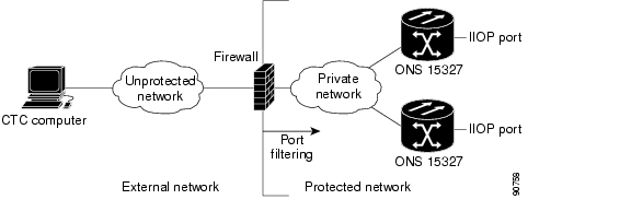
Figure 3-1 shows an ONS 15327 in a protected network and the CTC computer in an external network. For the computer to access the ONS 15327s, you must provision the IIOP listener port specified by your firewall administrator on the ONS 15327.

Figure 3-1 ONS 15327 Nodes Residing Behind a Firewall

Step 3 If the CTC computer resides behind a firewall, complete the "DLP-B68 Provision the IIOP Listener Port on the CTC Computer" task.

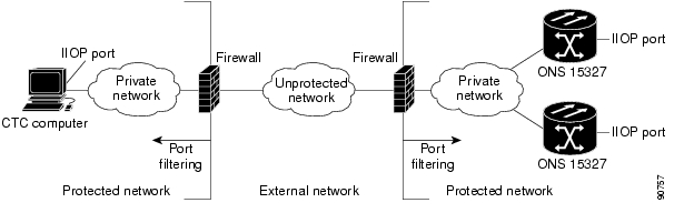
Figure 3-2 shows a CTC computer and ONS 15327 behind firewalls. For the computer to access the ONS 15327, you must provision the IIOP port on the CTC computer and on the ONS 15327.

Figure 3-2 A CTC Computer and ONS 15327s Residing Behind Firewalls

Stop. You have completed this procedure.


DLP-B67 Provision the IIOP Listener Port on the ONS 15327

Purpose

This task sets the IIOP listener port on the ONS 15327, which enables you to access ONS 15327s that reside behind a firewall.

Tools/Equipment

IIOP listener port number provided by your LAN or firewall administrator

Prerequisite Procedures

60 Log into CTC

Required/As Needed

As needed

Onsite/Remote

Onsite or remote

Security Level

Provisioning or higher


Step 1 In node view, click the Provisioning > Network tabs.

Step 2 On the General subtab under XTC CORBA (IIOP) Listener Port, choose a listener port option:

Default - XTC Fixed—Select this option if the ONS 15327s are on the same side of the firewall as the CTC computer or if no firewall is used (default). This option sets the ONS 15327 listener port to Port 57790. It can be used for access through a firewall if Port 57790 is open.

Standard Constant—Select this option to use Port 683, the CORBA default port number, as the ONS 15327 listener port.

Other Constant—If Port 683 is not used, type the IIOP port specified by your firewall administrator. The port cannot use any of the ports shown in Table 3-1.

Table 3-1 Ports Used by the XTC Cards 

Port
Function

0

Never used

21

FTP control

23

TELNET

80

HTTP

111

rpc (not used; but port is in use)

513

rlogin (not used; but port is in use)

=<1023

Default CTC listener ports

1080

Proxy server

2001-2017

I/O card telnet

2018

DCC processor on active XTC

2361

TL1

3082

TL1

3083

TL1

5001

BLSR server port

5002

BLSR client port

7200, 7209, 7210

SNMP input port

9100

EQM port

9101

EQM port 2

9401

XTC boot port

9999

Flash manager

57790

Default XTC listener port


Step 3 Click Apply.

Step 4 When the Change Network Configuration message appears, click Yes.

Both ONS 15327 XTCs will reboot, one at a time. The reboot will take approximately 10 to 15 minutes.

Step 5 Return to your originating procedure (NTP).


DLP-B68 Provision the IIOP Listener Port on the CTC Computer

Purpose

This task selects the IIOP listener port on CTC.

Tools/Equipment

IIOP listener port number provided by your LAN or firewall administrator

Prerequisite Procedures

60 Log into CTC

Required/As Needed

As needed

Onsite/Remote

Onsite or remote

Security Level

Provisioning or higher


Step 1 In node view, from the Edit menu choose Preferences.

Step 2 On the Preferences dialog box, click the Firewall tab.

Step 3 Under CTC CORBA (IIOP) Listener Port, choose a listener port option:

Default - Variable—Select this option if the ONS 15327s are on the same side of the firewall as the CTC computer or if no firewall is used (default). This option sets the CTC listener port to Port 57790. It can be used for access through a firewall if Port 57790 is open.

Standard Constant—Select this option to use Port 683, the CORBA default port number, as the CTC computer listener port.

Other Constant—If Port 683 is not used, enter the IIOP port provided by your administrator. The port cannot be set to any port listed in Table 3-1.

Step 4 Click Apply. A warning is displayed telling you that the port change will apply during the next CTC login.

Step 5 Click OK.

Step 6 On the Preferences dialog box, click OK. A warning appears telling you that the port change will apply during the next CTC login.

Step 7 To access the ONS 15327 using the IIOP port, log out of CTC (from the File menu, select Exit).

Step 8 Log into CTC. See the "DLP-B60 Log into CTC" task for instructions.

Step 9 Return to your originating procedure (NTP).


NTP-B28 Set Up Timing

Purpose

This procedure provisions the ONS 15327 timing.

Tools/Equipment

None

Prerequisite Procedures

24 Verify Card Installation

Required/As Needed

Required

Onsite/Remote

Onsite or remote

Security Level

Provisioning or higher


Step 1 Log into the ONS 15327 node where you want to set up timing. See the "DLP-B60 Log into CTC" task for instructions. If you are already logged in, continue with Step 2.

Step 2 Complete the "DLP-B69 Set Up External or Line Timing" task if an external BITS source is available. This is the most common SONET timing setup procedure.

Step 3 Complete the "DLP-B70 Set Up Internal Timing" task if you cannot complete Step 2 (an external BITS source is not available). This task can only provide Stratum 3 timing.


Note For information about SONET timing, refer to the Cisco ONS 15327 Reference Manual or to Telcordia GR-253-CORE.


Stop. You have completed this procedure.


DLP-B69 Set Up External or Line Timing

Purpose

This task defines the external or line SONET timing source for the ONS 15327.

Tools/Equipment

None

Prerequisite Procedures

60 Log into CTC

Required/As Needed

Required

Onsite/Remote

Onsite or remote

Security Level

Provisioning or higher


Step 1 In the node view, click the Provisioning > Timing tabs.

Step 2 Under General Timing, complete the following information:

Timing Mode—Choose External if the ONS 15327 derives its timing from a BITS source wired to the port on the MIC; choose Line if timing is derived from an OC-N card that is optically connected to the timing node. A third option, Mixed, allows you to set external and line timing references.


Note Because Mixed timing may cause timing loops, Cisco does not recommend its use. Use this mode with care.


SSM Message Set—Choose the message set level supported by your network. If a Generation 1 node receives a Generation 2 message, the message will be mapped down to the next available Generation 1. For example, an ST3E message becomes an ST3.

Quality of RES—If your timing source supports the reserved S1 byte, set the timing quality here. (Most timing sources do not use RES.) Qualities are displayed in descending quality order as ranges. For example, ST3<RES<ST2 means the timing reference is higher than a Stratum 3 and lower than a Stratum 2. Refer to the Cisco ONS 15327 Reference Manual for more information about SSM, including definitions of the SONET timing levels.

Revertive—Check this check box if you want the ONS 15327 to revert to a primary reference source after the conditions that caused it to switch to a secondary timing reference are corrected.

Reversion Time—If Revertive is checked, choose the amount of time the ONS 15327 will wait before reverting to its primary timing source. Five minutes is the default.

Step 3 Under BITS Facilities, complete the following information:


Note The BITS Facilities section sets the parameters for your BITS1 and BITS2 timing references. Many of these settings are determined by the timing source manufacturer. If equipment is timed through BITS Out, you can set timing parameters to meet the requirements of the equipment.


State—For line-timed nodes with no equipment timed through BITS Out, set State to OOS (Out of Service). For nodes using external timing or line timing with equipment timed through BITS Out, set the state to IS (In Service).

Step 4 If the state is set to OOS, continue with Step 5. If the state is set to IS, complete the following information:

Coding—Choose the coding used by your BITS reference, either B8ZS or AMI.

Framing—Choose the framing used by your BITS reference, either ESF (Extended Super Frame, or SF (D4) (Super Frame).

Sync Messaging—Check this check box to enable SSM. SSM is not available if Framing is set to Super Frame.

AIS Threshold—If SSM is disabled or Super Frame is used, choose the quality level where a node sends an alarm indication signal (AIS) from the BITS 1 Out and BITS 2 Out backplane pins. An AIS alarm is raised when the optical source for the BITS reference falls to or below the SSM quality level defined in this field.

LBO—If you are timing an external device connected to the BITS Out pins, choose the distance between the device and the ONS 15327. Options are: 0-133 ft. (default), 124-266 ft., 267-399 ft., 400-533 ft., and 534-655 ft.

Step 5 Under Reference Lists, complete the following information:


Note You can define up to three timing references for the node and up to six BITS Out references. BITS Out references define the timing references used by equipment that can be attached to the node's BITS Out connections on the MIC. If you attach equipment to BITS Out connections, you normally attach it to a node with Line mode because equipment near the external timing reference can be directly wired to the reference.


NE Reference—Allows you to define three timing references (Ref 1, Ref 2, Ref 3). The node uses Reference 1 unless a failure occurs to that reference, in which case the node uses Reference 2. If Reference 2 fails, the node uses Reference 3, which is typically set to Internal Clock. The internal clock is the Stratum 3 clock provided on the XTC. The options displayed depend on the Timing Mode setting.

If the Timing Mode is set to External, your options are BITS1, BITS2, and Internal Clock.

If the Timing Mode is set to Line, your options are the node's working OC-N cards and Internal Clock. Choose the cards/ports that are directly or indirectly connected to the node wired to the BITS source, that is, the node's trunk (span) cards. Set Reference 1 to the trunk card that is closest to the BITS source. For example, if Slot 5 is connected to the node wired to the BITS source, choose Slot 5 as Reference 1.

If the Timing Mode is set to Mixed, both BITS and OC-N cards are available, allowing you to set a mixture of external BITS and OC-N trunk (span) cards as timing references.

BITS 1 Out/BITS 2 Out—Define the timing references for equipment wired to the BITS Out connections on the MIC. Normally, BITS Out is used with line-timed nodes, so the options displayed are the working OC-N cards. BITS 1 and BITS 2 Out are enabled when BITS-1 and BITS-2 facilities are placed in service.

Step 6 Click Apply.


Note Refer to the Cisco ONS 15327 Troubleshooting Guide for timing-related alarms.


Step 7 Return to your originating procedure (NTP).


DLP-B70 Set Up Internal Timing

Purpose

This task sets up internal Stratum 3 timing for an ONS 15327.

Tools/Equipment

None

Prerequisite Procedures

60 Log into CTC

Required/As Needed

As needed (use only if a BITS source is not available)

Onsite/Remote

Onsite or remote

Security Level

Provisioning or higher


Caution Internal timing is Stratum 3 and not intended for permanent use. All ONS 15327s should be timed to a Stratum 2 or better primary reference source.


Step 1 In node view, click the Provisioning > Timing tabs.

Step 2 Under General Timing, enter the following:

Timing Mode—Set to External

SSM Message Set—Set to Generation 1

Quality of RES—Not relevant to internal timing; ignore this field

Revertive—Not relevant to internal timing; ignore this field

Reversion Time—Not relevant to internal timing; ignore this field

Step 3 Under BITS Facilities, change State to OOS (Out of Service). Disregard the other BITS Facilities settings; they are not relevant to internal timing.

Step 4 Under Reference Lists, enter the following information:

NE Reference

Ref 1—Set to Internal Clock

Ref 2—Set to Internal Clock

Ref 3—Set to Internal Clock

BITS 1 Out/BITS 2 Out—Set to None

Step 5 Click Apply.

Step 6 Log into a node that will be timed from the node you set up in Steps 1 to 5.

Step 7 Click the Provisioning > Timing tabs.

Step 8 In the General Timing section, enter the same information as entered in Step 2 with the following exceptions:

Timing Mode—Set to Line

Reference Lists

NE Reference

Ref 1—Set to the OC-N trunk card with the closest connection to the node in Step 3

Ref 2—Set to the OC-N trunk card with the next closest connection to the node in Step 3

Ref 3—Set to Internal Clock

Step 9 Click Apply.

Step 10 Repeat Steps 6 through 9 at each node that will be timed by the node in Step 3.

Step 11 Return to your originating procedure (NTP).


NTP-B170 Create Optical Protection Groups

Purpose

This procedure creates ONS 15327 card protection groups.

Tools/Equipment

None

Prerequisite Procedures

24 Verify Card Installation

Required/As Needed

Required; some network information is optional, depending on your site plan

Onsite/Remote

Onsite or remote

Security Level

Provisioning or higher


Note A 1:1 (electrical) protection group is preprovisioned on the ONS 15327 XTC card. The name of the protection group is XTCPROTGRP, and it cannot be edited or deleted. Therefore, you only need to create protection for optical cards.


Step 1 Complete the "DLP-B60 Log into CTC" task at the node where you want to create the protection group. If you are already logged in, continue with Step 2.

Step 2 From node view, click the Provisioning > Protection tabs.

Step 3 Under Protection Groups, click Create.

Step 4 In the Create Protection Group dialog box, enter the following:

Name—Type a name for the protection group. The name can have up to 32 alphanumeric characters.

Type—Choose 1+1 from the pull-down menu.

Protect Port—Choose the protect port from the pull-down menu. The menu displays the available OC-N ports. If OC-N cards are not installed, no ports display in the pull-down menu.

After you choose the protect port, a list of ports available for protection is displayed under Available Ports. If no cards are available, no ports are displayed. If this occurs, you will not be able to complete this task until you install the physical cards or preprovision the ONS 15327 slots.

Step 5 From the Available Ports list, choose the port that will be protected by the port you selected in Protect Ports. Click the top arrow button to move each port to the Working Ports list.

Step 6 Complete the remaining fields:

Bidirectional switching—Check this check box if you want both Tx and Rx signals to switch to the protect port when a failure occurs to one signal. Leave it unchecked if you want only the failed signal to switch to the protect port.

Revertive—Check this check box if you want traffic to revert to the working card after failure conditions stay corrected for the amount of time entered in the Reversion Time field.

Reversion time—If Revertive is checked, choose the reversion time from the pull-down menu. The range is 0.5 to 12.0 minutes. The default is 5.0 minutes. Reversion time is the amount of time that will elapse before the traffic reverts to the working card. Traffic can revert when conditions causing the switch are cleared.

Step 7 Click OK.

Step 8 Return to your originating procedure (NTP).


NTP-B171 Set Up SNMP

Purpose

This procedure provisions the SNMP parameters so that you can use SNMP management software with the ONS 15327.

Tools/Equipment

None

Prerequisite Procedures

24 Verify Card Installation

Required/As Needed

As needed

Onsite/Remote

Onsite or remote

Security Level

Provisioning or higher


Step 1 Complete the "DLP-B60 Log into CTC" task at the node where you want to set up SNMP. If you are already logged in, continue with Step 2.

Step 2 In node view, click the Provisioning > SNMP tabs.

Step 3 If you want the SNMP agent to accept SNMP SET requests on certain MIBs, click the Allow SNMP Sets check box. If this check box is not selected, SET requests are rejected.

Step 4 Click the Create button.

Step 5 In the SNMP Traps Destination dialog box ( Figure 3-3), complete the following:

IP Address—Type the IP address of your network management system. If the node you are logged into is an ENE, type the IP address of the ONS 15327 GNE.

Community Name—Type the SNMP community name. For a description of SNMP community names, refer to the SNMP information in the Cisco ONS 15327 Reference Manual.


Note The community name is a form of authentication and access control. The community name assigned to the ONS 15327 is case-sensitive and must match the community name of the NMS.


UDP Port—The default UDP port for SNMP is 162. If the node is an ENE in a proxy server network, the UDP port must be set to the GNE's SNMP relay port which is 391.

Trap Version—Choose either SNMPv1 or SNMPv2. Refer to your NMS documentation to determine the version to use.

Max Traps per Second—Type the maximum traps per second. The default is 0.


Note The Max Traps per Second is the maximum number of traps per second that will be sent to the SNMP manager. If the field is set to 0, there is no maximum and all traps are sent.


Figure 3-3 Setting SNMP

Step 6 Click OK.

Step 7 Click the node IP address under Trap Destinations ( Figure 3-4). Verify the SNMP information that appears under Selected Destination.

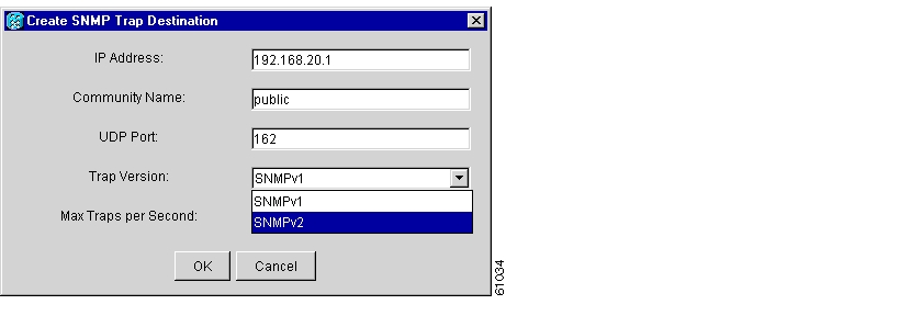
Figure 3-4 SNMP Trap Destinations

Stop. You have completed this procedure.


NTP-B34 Create Ethernet RMON Alarm Thresholds

Purpose

This procedure sets up remote monitoring (RMON) to allow network management systems to monitor Ethernet ports.

Tools/Equipment

None

Prerequisite Procedures

24 Verify Card Installation

Required/As Needed

As needed

Onsite/Remote

Onsite or remote

Security Level

Provisioning or higher


Step 1 Log into the ONS 15327 node where you want to set up SNMP. See the "DLP-B60 Log into CTC" task for instructions. If you are already logged in, continue with Step 2.

Step 2 In node view, click the Provisioning > Ether Bridge > Thresholds tabs.

Step 3 Click Create.

The Create Ether Threshold dialog box opens ( Figure 3-5).

Figure 3-5 Creating RMON Thresholds

Step 4 From the Slot pull-down menu, choose the appropriate Ethernet card.

Step 5 From the Port pull-down menu, choose the applicable port on the Ethernet card you selected.

Step 6 From the Variable pull-down menu, choose the variable. See Table 3-2 for a list of the Ethernet threshold variables available in this field.

Step 7 From the Alarm Type pull-down menu, indicate whether the event will be triggered by the rising threshold, falling threshold, or both the rising and falling thresholds.

Step 8 From the Sample Type pull-down menu, choose either Relative or Absolute. Relative restricts the threshold to use the number of occurrences in the user-set sample period. Absolute sets the threshold to use the total number of occurrences, regardless of time period.

Step 9 Type in an appropriate number of seconds for the Sample Period.

Step 10 Type in the appropriate number of occurrences for the Rising Threshold.


Note For a rising type of alarm, the measured value must move from below the falling threshold to above the rising threshold. For example, if a network is running below a falling threshold of 400 collisions every 15 seconds and a problem causes 1001 collisions in 15 seconds, these occurrences raise an alarm.


Step 11 Enter the appropriate number of occurrences in the Falling Threshold field. In most cases a falling threshold is set lower than the rising threshold.

A falling threshold is the counterpart to a rising threshold. When the number of occurrences is above the rising threshold and then drops below a falling threshold, it resets the rising threshold. For example, when the network problem that caused 1001 collisions in 15 minutes subsides and creates only 799 collisions in 15 minutes, occurrences fall below a falling threshold of 800 collisions. This resets the rising threshold so that if network collisions again spike over a 1000 per 15 minute period, an event again triggers when the rising threshold is crossed. An event is triggered only the first time a rising threshold is exceeded (otherwise a single network problem might cause a rising threshold to be exceeded multiple times and cause a flood of events).

Step 12 Click OK to complete the procedure.

Table 3-2 Ethernet Threshold Variables (MIBs) 

Variable
Definition

iflnOctets

Total number of octets received on the interface, including framing octets

iflnUcastPkts

Total number of unicast packets delivered to an appropriate protocol

ifInMulticastPkts

Number of multicast frames received error free

ifInBroadcastPkts

The number of packets, delivered by this sub-layer to a higher (sub-)layer, which were addressed to a broadcast address at this sub-layer

ifInDiscards

The number of inbound packets which were chosen to be discarded even though no errors had been detected to prevent their being deliverable to a higher-layer protocol

iflnErrors

Number of inbound packets discarded because they contain errors

ifOutOctets

Total number of transmitted octets, including framing packets

ifOutUcastPkts

Total number of unicast packets requested to transmit to a single address

ifOutMulticastPkts

Number of multicast frames transmitted error free

ifOutBroadcastPkts

The total number of packets that higher-level protocols requested be transmitted, and which were addressed to a broadcast address at this sub-layer, including those that were discarded or not sent

ifOutDiscards

The number of outbound packets that were chosen to be discarded even though no errors had been detected to prevent their being transmitted

dot3statsAlignmentErrors

Number of frames with an alignment error, i.e., the length is not an integral number of octets and the frame cannot pass the Frame Check Sequence (FCS) test

dot3StatsFCSErrors

Number of frames with framecheck errors, i.e., there is an integral number of octets, but an incorrect Frame Check Sequence (FCS)

dot3StatsSingleCollisionFrames

Number of successfully transmitted frames that had exactly one collision

dot3StatsMutlipleCollisionFrame

Number of successfully transmitted frames that had multiple collisions

dot3StatsDeferredTransmissions

Number of times the first transmission was delayed because the medium was busy

dot3StatsLateCollision

Number of times that a collision was detected later than 64 octets into the transmission (also added into collision count)

dot3StatsExcessiveCollision

Number of frames where transmissions failed because of excessive collisions

dot3StatsCarrierSenseErrors

The number of transmission errors on a particular interface that are not otherwise counted

dot3StatsSQETestErrors

A count of times that the SQE TEST ERROR message is generated by the PLS sublayer for a particular interface

etherStatsJabbers

Total number of Octets of data (including bad packets) received on the network

etherStatsUndersizePkts

Number of packets received with a length less than 64 octets

etherStatsFragments

Total number of packets that are not an integral number of octets or have a bad FCS, and that are less than 64 octets long

etherStatsPkts64Octets

Total number of packets received (including error packets) that were 64 octets in length

etherStatsPkts65to127Octets

Total number of packets received (including error packets) that were 65 - 172 octets in length

etherStatsPkts128to255Octets

Total number of packets received (including error packets) that were 128 - 255 octets in length

etherStatsPkts256to511Octets

Total number of packets received (including error packets) that were 256 - 511 octets in length

etherStatsPkts512to1023Octets

Total number of packets received (including error packets) that were 512 - 1023 octets in length

etherStatsPkts1024to1518Octets

Total number of packets received (including error packets) that were 1024 - 1518 octets in length

etherStatsJabbers

Total number of packets longer than 1518 octets that were not an integral number of octets or had a bad FCS

etherStatsCollisions

Best estimate of the total number of collisions on this segment

etherStatsCollisionFrames

Best estimate of the total number of frame collisions on this segment

etherStatsCRCAlignErrors

Total number of packets with a length between 64 and 1518 octets, inclusive, that had a bad FCS or were not an integral number of octets in length

receivePauseFrames (G series only)

The number of received 802.x pause frames

transmitPauseFrames (G series only)

The number of transmitted 802.x pause frames

receivePktsDroppedInternalCongestion (G series only)

The number of received framed dropped due to frame buffer overflow as well as other reasons

transmitPktsDroppedInternalCongestion (G series only)

The number of frames dropped in the transmit direction due to frame buffer overflow as well as other reasons

txTotalPkts

Total number of transmit packets

rxTotalPkts

Total number of receive packets


Stop. You have completed this procedure.


hometocprevnextglossaryfeedbacksearchhelp

Posted: Mon Feb 25 06:25:35 PST 2008
All contents are Copyright © 1992--2008 Cisco Systems, Inc. All rights reserved.
Important Notices and Privacy Statement.