|
|

Table Of Contents
Troubleshooting a Cisco 7500 Series Router
Problem Solving with Cisco 7500 Series Subsystems
Troubleshooting Guidelines for the Cisco 7505
Identifying Cisco 7505 Startup Problems
Troubleshooting the Cisco 7505 Power Subsystem
Troubleshooting the Cisco 7505 Cooling Subsystem
Troubleshooting Guidelines for the Cisco 7507 and
Cisco 7507-MXIdentifying Cisco 7507 and Cisco 7507-MX Startup Problems
Troubleshooting the Cisco 7507 and Cisco 7507-MX Power Subsystem
Troubleshooting the Cisco 7507 and Cisco 7507-MX Cooling Subsystem
Troubleshooting Guidelines for the Cisco 7513,
Cisco 7513-MX, and Cisco 7576Identifying Cisco 7513, Cisco 7513-MX, and Cisco 7576 Startup Problems
Troubleshooting the Cisco 7513, Cisco 7513-MX, and Cisco 7576 Power Subsystem
Troubleshooting the Cisco 7513, Cisco 7513-MX, and Cisco 7576 Cooling Subsystem
Troubleshooting Blower Operation
Troubleshooting the Cisco 7500 Series Processor Subsystem
Troubleshooting the Interface Processors
Using Cisco 7500 Series System LEDs
Using the Front-Panel System LEDs
Additional Reference Information for Troubleshooting
Troubleshooting a Cisco 7500 Series Router
Your Cisco 7500 series router went through extensive testing and burn-in before leaving the factory; however, if you encounter problems starting up the router, use the information in this chapter to help isolate the cause. Problems with the initial startup will most likely be caused by the source power or a processor module that has become dislodged from the backplane.
Although an overtemperature or overvoltage condition is unlikely at initial startup, a discussion of environmental temperature and voltage monitoring functions is provided in the "Environmental Monitoring and Reporting Overview for the Cisco 7500 Series" section.
Note
The procedures in this chapter assume that you are troubleshooting the initial Cisco 7500 series system startup, and that the router is in the original factory configuration. If you have removed or replaced components or changed any default settings, the recommendations in this chapter might not apply.
The Cisco 7505 uses a single RSP2 main system processor. It is also compatible with an RSP4 and RSP8 as an upgrade option.
The Cisco 7507, Cisco 7507-MX, Cisco 7513, and Cisco 7513-MX use up to two RSP2s, RSP4s, or RSP8s, or one of each. Two RSPs in any combination are required in these routers only when you have the high system availability (HSA) feature enabled; otherwise, only one RSP2, RSP4, or RSP8 is allowed.
Note
The following sections contain Cisco 7500 series troubleshooting information:
•
After reading the preceding sections, choose the specific section or sections that apply to your Cisco 7500 series router:
•
•
•
The following sections pertain to all of the Cisco 7500 series routers.
•
•
•
•
Troubleshooting Overview
At the initial system boot, you should verify the following:
•
•
•
•
Note
If you determine that your loaded and running Cisco IOS software is not compatible with your Cisco 7500 series router, or you suspect it might not be compatible with your interface processor, see the "Preface" chapter for instructions on how to obtain technical assistance.When each of these conditions is met, the hardware installation is complete, and you should proceed to "Performing a Basic Configuration of the System," to perform a basic system configuration. You should also refer to the appropriate companion software-configuration documentation to fully configure the Cisco IOS software, protocols, and individual interfaces in your system. If the startup sequence fails before these conditions are met, use the procedures in this chapter to isolate and, if possible, resolve the problem.
If you are unable to easily solve the problem, contact a customer service representative for assistance and further instructions. Before you call, have the following information ready to help your service provider assist you as quickly as possible:
•
•
•
•
•
Problem Solving with Cisco 7500 Series Subsystems
The key to solving problems in the system is to try to isolate the problem to a specific subsystem. The first step in solving startup problems is to compare what the system is doing to what it should be doing. Because a startup problem is usually attributable to a single component, it is more efficient to first isolate the problem to a subsystem rather than troubleshoot each component in the system.
For the troubleshooting procedures in this chapter, the Cisco 7500 series consists of the following subsystems:
•
•
The variable speed feature in the Cisco 7513, Cisco 7513-MX, and Cisco 7576 allows the blower to operate at a slower speed and provide quieter operation when the internal chassis temperature is within the normal operating range. If the internal temperature exceeds a specified temperature, the blower speed increases to move more cooling air through the chassis. As a result, it may be difficult to determine whether or not the blower is operating in noisy, air-conditioned rooms. If you determine that the blower is not operating, contact a service representative immediately; there are no installation adjustments that you should make.
•
The following sections will help you isolate a problem in a Cisco 7500 series router and one of its subsystems, and will direct you to the appropriate troubleshooting information:
•
•
•
•
Troubleshooting Guidelines for the Cisco 7505
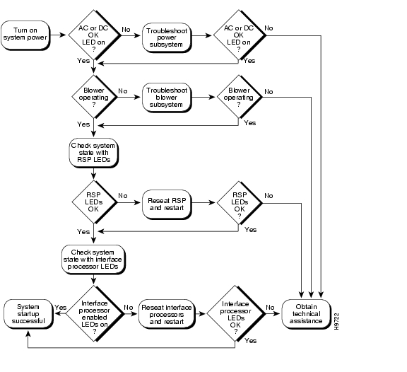
Figure 8-1 shows the general troubleshooting strategy for the Cisco 7505. Refer to this chart to isolate problems and resolve a problem, if possible.
Figure 8-1 Troubleshooting Strategy for Cisco 7505 Startup Problems
Identifying Cisco 7505 Startup Problems
When you start up the router for the first time, you should observe the startup sequence described in the "Starting the System and Observing Initial Conditions" section. This section contains a more detailed description of the normal startup sequence and describes the steps to take if the system does not perform that sequence as expected.
By checking the state of the LEDs on the power supply and processor modules (the RSP and interface processors), you can determine when and where the system failed in the startup sequence. Use the following descriptions to isolate the problem to a subsystem; then proceed to the appropriate sections (indicated in each description) to try to resolve the problem.
When you start up the system by turning on the main system power switch on the interface processor end of the power supply, the following should occur:
•
The green DC OK LED indicates the status of the power supply and internal DC voltages. The DC OK LED stays on when all of the following conditions are met:
–
–
–
If the AC or DC source power or any of the internal DC voltages exceeds allowable tolerances, the DC OK LED will not go on or will go off shortly after you turn on the power. Because both the RSP (which uses +5, +12, -12 VDC) and the fan tray (which uses +24 VDC) are required for operation, a problem with any of the internal DC lines can prevent the system from starting up or continuing operation.
For example, if there is a problem with the +24 VDC line that supplies the fan tray, the system will start up but also recognize that the fans are not operating. The system will initiate a fan failure shutdown sequence, display the appropriate warning messages, and then shut down after 2 minutes. If there is a problem with any of the other DC lines, the RSP will not be able to initialize the system software, so the system might attempt to start up and fail during the boot sequence.
Depending on when the DC OK LED goes off, proceed as follows:
–
–
–
%ENVM-2-FAN: Fan array has failed, shutdown in 2 minutes–
•
–
–
•
•
Note
When the LEDs indicate that the system has initialized successfully, the system banner (similar to the following example) should be displayed on the console screen. If it is not displayed, see the "Connecting a Console Terminal to the RSP" section to verify that the terminal is set correctly and that it is properly connected to the RSP console port.
System Bootstrap, Version 4.6(5), SOFTWARECopyright (c) 1986-1995 by cisco SystemsRSP2 processor with 16384 Kbytes of memory(display text omitted)F3: 2012356+47852+194864 at 0x1000Restricted Rights LegendUse, duplication, or disclosure by the Government issubject to restrictions as set forth in subparagraph(c) of the Commercial Computer Software - RestrictedRights clause at FAR sec. 52.227-19 and subparagraph(c) (1) (ii) of the Rights in Technical Data and ComputerSoftware clause at DFARS sec. 252.227-7013.cisco Systems, Inc.170 Tasman DriveSan Jose, CA 95134GS Software (GS7), Version 10.3(3) [fc3], RELEASE SOFTWARECopyright (c) 1986-1995 by cisco Systems, Inc.(display text omitted)Press RETURN to get started!Troubleshooting the Cisco 7505 Power Subsystem
This section provides information on troubleshooting the Cisco 7505 power subsystem.
Check the following to help isolate the problem: On the interface processor end of the power supply, is the DC OK LED on?
•
•
•
•
–
–
If you are unable to resolve the problem or if you determine that either the power supply or the power cable is faulty, contact a service representative for instructions.
Troubleshooting the Cisco 7505 Cooling Subsystem
This section provides information on troubleshooting the Cisco 7505 cooling subsystem.
Check the following to help isolate the problem:
•
To determine whether the fans are operating, listen for the fan motors. In noisy environments, place your hand next to the left side of the chassis (when facing the interface processor end of the router) to feel for air being forced out the side vents.
–
–
–
•
–
–
%ENVM-2-FAN: Fan array has failed, shutdown in 2 minutesIf one or more fans or the fan control board fails, you must replace the fan tray.
–
Queued messages:%ENVM-1-SHUTDOWN: Environmental Monitor initiated shutdownIf an environmental shutdown results from an out-of-tolerance power condition, the DC OK LED will go off before the system shuts down. (See the "Troubleshooting the Cisco 7505 Power Subsystem" section.)
Although an overtemperature condition is unlikely at initial startup, ensure that heated exhaust air from other equipment is not entering the inlet vents, and that there is sufficient clearance around the sides of the chassis to allow cooling air to flow. See the guidelines in "Preparing for Installation," for preventive site preparation information.
This message could also indicate a faulty component or temperature sensor. Before the system shuts down, use the show environment or show environment table command to display the internal chassis environment. (For detailed descriptions of show commands, see the "Cisco 7505 Environmental show Command Examples" section.)
If you are still unable to resolve the problem, contact a service representative for further instructions.
Troubleshooting Guidelines for the Cisco 7507 and
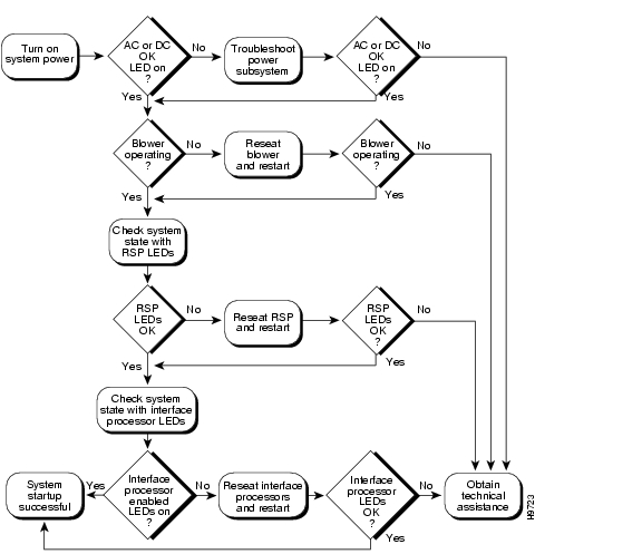
Cisco 7507-MXFigure 8-2 shows the general troubleshooting strategy for the Cisco 7507 and Cisco 7507-MX. Refer to this chart to isolate problems to a specific subsystem and resolve the problem, if possible.
Figure 8-2 Troubleshooting Strategy for Cisco 7507 and Cisco 7507-MX Startup Problems
Identifying Cisco 7507 and Cisco 7507-MX Startup Problems
When you start up the router for the first time, you should observe the startup sequence described in the "Starting the System and Observing Initial Conditions" section. This section contains a more detailed description of the normal startup sequence and describes the steps to take if the system does not perform that sequence as expected.
With the exception of the system blower, LEDs indicate all system states in the startup sequence. By checking the state of the LEDs, you can determine when and where the system failed in the startup sequence. Use the following descriptions to isolate the problem to a subsystem, and then proceed to the appropriate sections (indicated in each description) to try to resolve the problem.
When you start up the system by turning on the power supply switches, the following should occur:
•
•
–
–
•
•
When all LEDs come on to indicate that the system has booted successfully, the initial system banner should be displayed on the console screen. If it is not displayed, see the "Connecting a Console Terminal to the RSP" section to verify that the terminal is set correctly and that it is properly connected to the RSP console port.
Troubleshooting the Cisco 7507 and Cisco 7507-MX Power Subsystem
This section provides information on troubleshooting the Cisco 7507 and Cisco 7507-MX power subsystem.
Check the following to help isolate the problem:
•
–
–
Tighten the captive installation screw, and then turn the power switch clockwise until it is completely turned to the on (|) position and the interlock tab is fully extended into the interlock slot in the chassis. (See the "Installing Cisco 7507 and Cisco 7507-MX Power Supplies" section.)
–
If the LED fails to come on after you connect the power supply to a new power source, replace the power cord and turn the switch back on. If the AC power (or input power) LED then comes on, return the first power cable for replacement.
If the LED still fails to come on when connected to a different power source with a new power cable, the power supply is probably faulty. If a second power supply is available, install it in the lower power supply bay and contact a service representative for further instructions.
•
If yes, suspect the power supply. Try installing the power supply in the upper bay. If a second power supply is present, move it to the lower bay. Turn both power supplies on to determine whether the power supply or the power connector in the chassis is faulty; then contact a service representative with the results.
•
If not, repeat each of the above procedures for the second power supply.
If you are unable to resolve the problem or if you determine that either a power supply or a chassis connector is faulty, contact a service representative for instructions.
Troubleshooting the Cisco 7507 and Cisco 7507-MX Cooling Subsystem
This section provides information on troubleshooting the Cisco 7507 and Cisco 7507-MX cooling subsystem.
Check the following to help isolate the problem:
When you start up the system, does the system blower go on? To determine whether the blower is operating, listen for the motor. In noisy environments, place your hand above and to each side of the processor slots on the rear of the chassis (when facing the interface processor end of the router) to feel for air being forced out the vents.
•
•
•
•
Queued messages:%ENVM-1-SHUTDOWN: Environmental Monitor initiated shutdownIf an environmental shutdown results from an out-of-tolerance power condition, the DC OK LED will go off before the system shuts down. (See the "Troubleshooting the Cisco 7507 and Cisco 7507-MX Power Subsystem" section.) Although an overtemperature condition is unlikely at initial startup, ensure that heated exhaust air from other equipment is not entering the inlet vents, and that there is sufficient clearance around the sides of the chassis to allow cooling air to flow. See the "Cisco 7507 and Cisco 7507-MX Airflow Considerations" section for preventive site configurations.
This message could also indicate a faulty component or temperature sensor. Before the system shuts down, use the show environment or show environment table command to display the internal chassis environment. (For detailed descriptions of show commands, see the "Cisco 7507 and Cisco 7507-MX Environmental show Command Examples" section.)
If you are still unable to resolve the problem, contact a service representative for further instructions.
Troubleshooting Guidelines for the Cisco 7513,
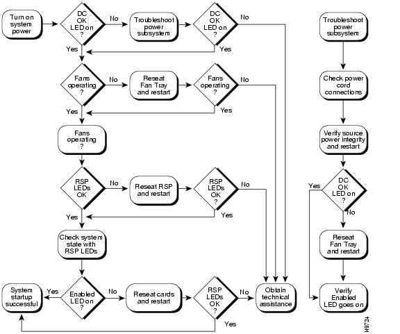
Cisco 7513-MX, and Cisco 7576Figure 8-3 shows the general troubleshooting strategy for the Cisco 7513, Cisco 7513-MX, and Cisco 7576. Refer to this chart to isolate problems to a specific subsystem and resolve the problem, if possible.
Figure 8-3 Troubleshooting Strategy for Cisco 7513, Cisco 7513-MX, and Cisco 7576 Startup Problems
Identifying Cisco 7513, Cisco 7513-MX, and Cisco 7576 Startup Problems
When you start up the router for the first time, you should observe the startup sequence described in the "Starting the System and Observing Initial Conditions" section. This section contains a more detailed description of the normal startup sequence and describes the steps to take if the system does not perform that sequence as expected.
By checking the state of the LEDs on the power supplies and processor modules (the RSP and interface processors), you can determine when and where the system failed in the startup sequence. Use the following descriptions to isolate the problem to a subsystem, and then proceed to the appropriate sections (indicated in each description) to try to resolve the problem.
When you start up the system by turning on the main system power switch on the interface processor end of the power supplies, the following should occur:
•
The green AC (or DC) OK LED indicates the status of the power supplies and internal DC voltages. The AC (or DC) OK LED stays on when all of the following conditions are met:
–
–
–
If the AC (or DC) source power or any of the internal DC voltages exceed allowable tolerances, the AC (or DC) OK LED will not go on or will go off shortly after you turn on the power. Because both the RSPs (which use +5, +12, and -12 VDC) and the blower module (which uses +24 VDC) are required for operation, a problem with any of the internal DC lines can prevent the system from starting up or continuing operation.
For example, if there is a problem with the +24 VDC line that supplies the blower module, the system will start up but also recognize that the blower is not operating. The system will initiate a blower failure shutdown sequence, display the appropriate warning messages, and then shut down after 2 minutes. If there is a problem with any of the other DC lines, the RSPs will not be able to initialize the system software, so the system might attempt to start up and fail during the boot sequence.
Depending upon when the DC OK LED goes off, proceed as follows:
–
–
–
%ENVM-2-FAN: Fan has failed, shutdown in 2 minutes–
•
Note
–
–
•
•
Note
When the LEDs indicate that the system has initialized successfully, the system banner (similar to the following example) should be displayed on the console screen. If it is not displayed, refer to the "Connecting a Console Terminal to the RSP" section to verify that the terminal is set correctly and that it is properly connected to the RSP's console port.
System Bootstrap, Version 4.6(5), SOFTWARECopyright (c) 1986-1995 by cisco SystemsRSP2 processor with 16384 Kbytes of memory(additional text omitted from this example)F3: 2012356+47852+194864 at 0x1000Restricted Rights LegendUse, duplication, or disclosure by the Government issubject to restrictions as set forth in subparagraph(c) of the Commercial Computer Software - RestrictedRights clause at FAR sec. 52.227-19 and subparagraph(c) (1) (ii) of the Rights in Technical Data and ComputerSoftware clause at DFARS sec. 252.227-7013.cisco Systems, Inc.170 Tasman DriveSan Jose, CA 95134GS Software (RSP-K), Version 10.3(571) [fc3], RELEASE SOFTWARECopyright (c) 1986-1995 by cisco Systems, Inc.(additional text omitted from this example)Press RETURN to get started!Troubleshooting the Cisco 7513, Cisco 7513-MX, and Cisco 7576 Power Subsystem
This section provides information on troubleshooting the Cisco 7513, Cisco 7513-MX, and Cisco 7576 power subsystem.
Check the following to help isolate the problem: On the interface processor end of the power supplies, are the AC (or DC) OK LEDs on?
•
•
•
–
–
–
If the AC (or DC) OK LED then goes on, return the faulty power supply for replacement.
If you are unable to resolve the problem or if you determine that either the power supply or power cable is faulty, contact a service representative for instructions.
Troubleshooting the Cisco 7513, Cisco 7513-MX, and Cisco 7576 Cooling Subsystem
This section provides information on troubleshooting the Cisco 7513, Cisco 7513-MX, and Cisco 7576 cooling subsystem.
Check the following to help isolate the problem:
•
To determine if the blower is operating, listen for the blower motor. In noisy environments, place your hand near the middle of the plastic panel on the front of the chassis (opposite the interface processor end of the chassis) to feel for air being forced out the exhaust vent.
–
–
–
•
–
–
%ENVM-2-FAN: Fan has failed, shutdown in 2 minutesIf the blower or the blower control board fails, you must replace the blower module.
–
Queued messages:%ENVM-1-SHUTDOWN: Environmental Monitor initiated shutdownIf an environmental shutdown results from an out-of-tolerance power condition, the output fail LED will go on before the system shuts down. See the "Troubleshooting the Cisco 7513, Cisco 7513-MX, and Cisco 7576 Power Subsystem" section.
Although an overtemperature condition is unlikely at initial startup, ensure that heated exhaust air from other equipment is not entering the inlet vents, and that there is sufficient clearance around the front and rear of the chassis to allow cooling air to flow. Refer to the guidelines in "Preparing for Installation," for preventive site preparation recommendations.
This message could also indicate a faulty component or temperature sensor. Before the system shuts down, use the show environment or show environment table commands to display the internal chassis environment. (For detailed descriptions of show commands, see the "Cisco 7513 and Cisco 7513-MX Environmental show Command Examples" section.)
If you are still unable to resolve the problem, contact a service representative for
further instructions.Troubleshooting Blower Operation
If you suspect your blower has failed, check the following to help isolate the problem:
•
To determine whether the blower is operating, listen for the blower motor. In noisy environments, place your hand next to the front of the chassis to feel for air being forced out the exhaust vent.
–
–
–
•
–
–
%ENVM-2-FAN: Fan has failed, shutdown in 2 minutesIf the blower or the blower control board fails, you must replace the blower module assembly.
–
Queued messages:%ENVM-1-SHUTDOWN: Environmental Monitor initiated shutdownIf an environmental shutdown results from an out-of-tolerance power condition, the output fail LED will go on before the system shuts down.
Although an overtemperature condition is unlikely at initial startup, ensure that heated exhaust air from other equipment is not entering the inlet vents, and that there is sufficient clearance around the sides of the chassis to allow cooling air to flow.
The preceding message could also indicate a faulty component or temperature sensor. Before the system shuts down, use the show environment or show environment table commands (See the "Cisco 7513 and Cisco 7513-MX Environmental show Command Examples" section to display the internal chassis environment.)
Troubleshooting the Cisco 7500 Series Processor Subsystem
The Cisco 7500 series processor subsystem comprises the RSPs and interface processors. The RSPs are required system components in the Cisco 7500 series. The system cannot operate unless the RSPs are installed properly; however, the system can operate without any interface processors installed as long as none are in partial contact with the backplane pins. An interface processor that is partially connected to the backplane will send incomplete signals to the processor, which will fault the bus and cause the system to hang. Therefore, first ensure that the RSPs are installed properly and the system software has initialized successfully. Then, if necessary, you can troubleshoot individual interface processors.
Two RSPs are required in the Cisco 7507, Cisco 7507-MX, Cisco 7513, or Cisco 7513-MX only when you have the high-system availability (HSA) feature enabled; otherwise, only one RSP is required. When using an RSP8 as the master device, the HSA feature functions only with another RSP8 as the slave device. The Cisco 7576 does not support HSA. Router A and router B in the Cisco 7576 operate with only one RSP.
Caution
Troubleshooting the RSP
The procedures in this section assume that the RSPs and router are in the original factory configuration, and that you have not changed any configuration register settings or made changes to your configuration file.
If you have made such changes, see the "Configuring the Software Configuration Register" section to reselect default values.
If the RSP LEDs do not go on as expected, check the following items to help isolate the problem.
•
–
–
–
•
If yes, the system software has initialized successfully, and the system is operational.
•
If yes, the system has detected a processor hardware failure. (This LED should be off in normal operation.) Contact a service representative for instructions.
Troubleshooting the Interface Processors
This section provides information on troubleshooting the interface processors.
Check the following to help isolate the problem:
•
If yes, the system is operational. Proceed to the instructions for configuring the interfaces in the appropriate software documentation.
•
–
–
Note
If you experience trouble with the startup that is not resolved with these procedures, contact a service representative for assistance and further instructions.
Using Cisco 7500 Series System LEDs
The RSPs and power supplies in all of the Cisco 7500 series routers have LEDs that indicate specific behavior. The Cisco 7507, Cisco 7507-MX, Cisco 7513, Cisco 7513-MX, and Cisco 7576 routers also have front-panel LEDs. (The Cisco 7505 does not have front-panel LEDs.)
Use the information in the following sections to interpret the LED indications for your system:
•
•
•
Note
Using the Front-Panel System LEDs
This section describes the indications for the front-panel LEDs on the Cisco 7507, Cisco 7507-MX, Cisco 7513, Cisco 7513-MX, and Cisco 7576. (The Cisco 7505 has no front-panel system LEDs.)
Cisco 7507 and Cisco 7507-MX LEDs
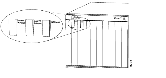
Three system status LEDs on the front of the Cisco 7507 and Cisco 7507-MX (see Figure 8-4) indicate the status of the system and the power supplies. The normal LED goes on to indicate that the system is in a normal operating state. The normal LED is controlled by the RSP2, which contains an identical normal LED that provides system status on the rear of the chassis.
The upper power and lower power LEDs go on to indicate that a power supply is installed in the indicated power supply bay and is providing power to the system. The power LEDs go out if the power supply in the corresponding bay reaches an out-of-tolerance temperature or voltage condition. (For detailed descriptions of the show commands that display temperature and voltage information, see the "Cisco 7507 and Cisco 7507-MX Environmental show Command Examples" section.)
Figure 8-4 Front Panel LEDs (Cisco 7507 and Cisco 7507-MX)
Cisco 7513, Cisco 7513-MX, and Cisco 7576 LEDs
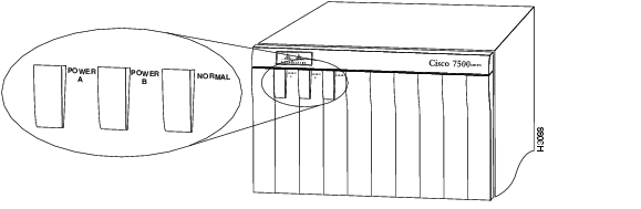
Three system status LEDs on the front of the Cisco 7513, Cisco 7513-MX, and Cisco 7576 (see Figure 8-5) indicate the status of the system and the power supplies. On the Cisco 7513 and Cisco 7513-MX the normal LED lights to indicate that the system is in a normal operating state. The normal LED is controlled by the RSP, which contains an identical normal LED that provides system status on the rear of the chassis.
Note
The power A and power B LEDs light to indicate that a power supply is installed in the indicated power supply bay and is providing power to the system. With the chassis oriented as shown in Figure 1-11, the power A bay is on the left and the power B bay is on the right.
Note
The power LEDs go out if the power supply in the corresponding bay reaches an out-of-tolerance temperature or voltage condition. (For detailed descriptions of the show commands that display temperature and voltage information, see the "Cisco 7513 and Cisco 7513-MX Environmental show Command Examples" section.)
Figure 8-5 Front Panel LEDs (Cisco 7513, Cisco 7513-MX, and Cisco 7576)
Using the RSP LEDs
This section describes the indications for the LEDs on the RSPs.
RSP2 LEDs—Cisco 7500 Series
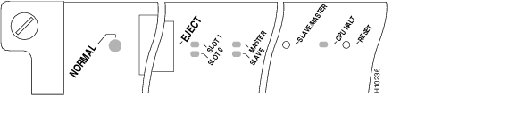
The two LEDs on the RSP2—normal and CPU halt (see Figure 8-6 )—indicate the system and RSP2 status. The normal LED goes on to indicate that the system is operational. During normal operation, the CPU halt LED on the RSP2 should be off and stay off unless the system detects a processor hardware failure. A successful boot is indicated when the normal LED comes on and stays on; however, this does not necessarily mean that the system has reached normal operation.
The slot 0 and slot 1 LEDs indicate which PC Card (Flash memory card) slot is in use and blink when either slot is being accessed by the system.
Figure 8-6 RSP2 LEDs (Partial Front Panel, Horizontal View)
Caution
Note
The Cisco 7576 does not support master/slave operation. Only one RSP is used per router; therefore, the RSP in slot 6 is automatically the system master for router A, and the RSP in slot 7 is automatically the system master for router B.RSP4 and RSP8 LEDs—Cisco 7500 Series
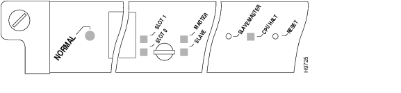
Figure 8-7 shows the LEDs on the RSP4 and RSP8 faceplate. The LEDs on the RSP4 and RSP8 indicate the system and RSP4 or RSP8 status and which Flash memory card slot is active. The CPU halt LED, which goes on only if the system detects a processor hardware failure, should remain off. A successful boot is indicated when the normal LED goes on; however, this does not necessarily mean that the system has reached normal operation. During normal operation, the CPU halt LED should be off, and the normal LED should be on, indicating that the RSP4 or RSP8 is receiving +5V. The slot 0 and slot 1 LEDs indicate which PC Card (Flash memory) card slot is in use, and each LED blinks when the card is accessed by the system. The master and slave LEDs provide a visual indication of whether the RSP4 is designated as a master or a slave device.
Note
Figure 8-7 RSP4 and RSP8 LEDs (Partial Front Panel, Horizontal View)
Caution
Using the Power Supply LEDs
This section describes the indications of the LEDs on the Cisco 7500 series power supplies.
Cisco 7505 Power Supply LED
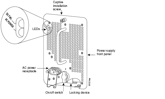
The DC OK LED (see Figure 8-8) on the interface processor end of the Cisco 7505 AC-input and DC-input power supplies goes on when the power supply is receiving AC or DC source power and providing DC power to the internal chassis components. The power supply self-monitors its own temperature and internal voltages. (For detailed descriptions of the show commands that display temperature and voltage information, see the "Cisco 7505 Environmental show Command Examples" section.)
Figure 8-8 Power Supply LED (AC-Input Power Supply Shown, Cisco 7505)
Cisco 7507 and Cisco 7507-MX Power Supply LEDs
There are two types of power supplies for the Cisco 7507 and Cisco 7507-MX: AC-input and DC-input. Each AC-input power supply has AC power and DC fail LEDs and a power switch, as shown in Figure 8-9 . The green AC power LED indicates that the power supply is turned on and is receiving input AC power. The yellow DC fail LED is normally off, but goes on if the power supply shuts down for any of the following reasons:
•
•
In systems with a single AC-input power supply, and in systems with redundant power, when both AC-input power supplies are being shut down, the DC fail LED goes on momentarily as the system ramps down, but is off when the power supply has completely shut down. In systems with redundant power where one power supply is still active, the DC fail LED on the failed power supply will remain on (powered by the active supply).
Figure 8-9 AC-Input Power Supply LEDs (Cisco 7507 and Cisco 7507-MX)
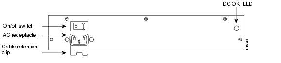
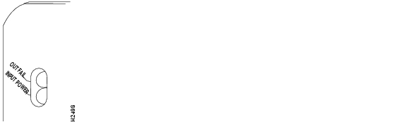
The DC-input power supply LEDs include the input power LED and the out fail LED. See Figure 8-10. The green input power LED is on when the input power is applied. The yellow out fail LED is normally off but flashes at power on for a lamp test.
The out fail LED goes on if the power supply shuts down for either of the following reasons:
•
•
Figure 8-10 DC-Input Power Supply LEDs, Cisco 7507 and Cisco 7507-MX (Same Location as AC-Input Power Supply)
In systems with a single DC-input power supply, and in systems with redundant power, when both power supplies are shutting down, the out fail LED goes on momentarily as the system ramps down, but goes out when the power supply has completely shut down. In systems with redundant power where one power supply is still active, the out fail LED on the failed power supply will remain on (powered by the active supply).
The AC-input and DC-input power supplies are self-monitoring. Each supply monitors its own temperature and internal voltages. (For detailed descriptions of the show commands that display temperature and voltage information, see the "Cisco 7507 and Cisco 7507-MX Environmental show Command Examples" section.)
Cisco 7513, Cisco 7513-MX, and Cisco 7576 Power Supply LEDs
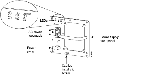
There are two types of power supplies for the Cisco 7513, Cisco 7513-MX, and Cisco 7576: AC-input and DC-input. Each power supply contains the following LEDs: AC (or DC) OK, fan OK, and output fail. Figure 8-11 shows the AC-input power LEDs, and Figure 8-12 shows the DC-input power LEDs.
Figure 8-11 AC-Input Power Supply LEDs (Cisco 7513, Cisco 7513-MX, and Cisco 7576)
The green AC (or DC) OK LED indicates that the power supply is turned on and is receiving input power. The red output fail LED is normally off but goes on if the power supply shuts down for any of the following reasons:
•
•
The green fan OK LED is on to indicate the fan in the power supply is operating properly. This LED is useful in noisy environments when you are troubleshooting a potential power supply problem and it is difficult to differentiate the sound of one power supply's fan from another.
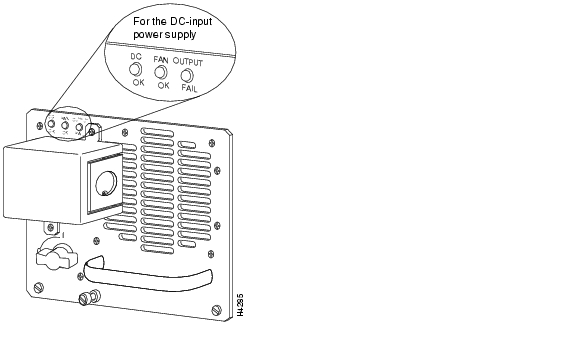
Figure 8-12 DC-Input Power Supply LEDs (Cisco 7513, Cisco 7513-MX, and Cisco 7576)
In systems with a single power supply, and in systems with redundant power when both power supplies are being shut down, the output fail LED lights momentarily as the system ramps down, but is off when the power supply has completely shut down.
The AC-input and DC-input power supplies are self-monitoring. Each supply monitors its own temperature and internal voltages. (For detailed descriptions of the show commands used to monitor environmental conditions, see the "Cisco 7513 and Cisco 7513-MX Environmental show Command Examples" section.)
Additional Reference Information for Troubleshooting
This section provides additional Cisco reference material for troubleshooting your Cisco 7500 series router installation:
•
•
•
•
•
![]()
![]()
![]()
![]()
![]()
![]()
![]()
![]()
Posted: Thu Mar 24 10:47:18 PST 2005
All contents are Copyright © 1992--2005 Cisco Systems, Inc. All rights reserved.
Important Notices and Privacy Statement.