cc/td/doc/product/core/cis7505
hometocprevnextglossaryfeedbacksearchhelp
PDF

Table Of Contents

Replacing DRAM on the Route Switch Processor

Upgrading or Replacing DRAM SIMMs on the RSP2

Removing RSP2 SIMMs

Installing New RSP2 SIMMs

Upgrading or Replacing DRAM DIMMs on the RSP4 and RSP8

Removing RSP4 and RSP8 DIMMs

Installing New RSP4 or RSP8 DIMMs


Replacing DRAM on the Route Switch Processor


This chapter describes the procedures for upgrading or replacing dynamic random-access memory (DRAM) on each of the RSPs used in the Cisco 7500 series routers. The RSP2 uses DRAM single in-line memory modules (SIMMS), and the RSP4 and RSP8 use DRAM dual in-line memory modules (DIMMS).

All DRAM upgrade procedures are discussed in the following sections:

Upgrading or Replacing DRAM SIMMs on the RSP2

Upgrading or Replacing DRAM DIMMs on the RSP4 and RSP8

Upgrading or Replacing DRAM SIMMs on the RSP2

This section describes the procedures for replacing up to four DRAM SIMMs on your RSP2. You obtain the SIMMs from Cisco Systems.

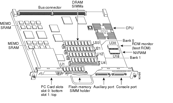
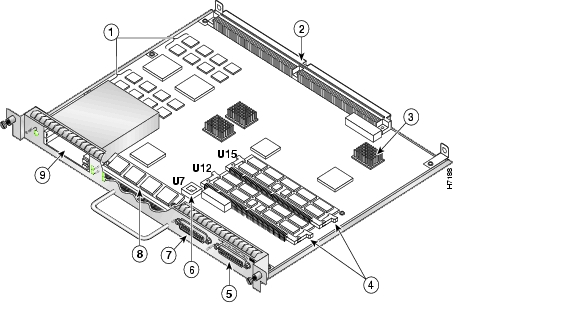
Figure 9-1 RSP2 DRAM SIMM Locations

The system DRAM resides in up to four SIMM sockets in two memory banks, 0 and 1. The DRAM SIMM sockets are U21 and U33 for bank 0, and U4 and U12 for bank 1. (See Figure 9-1.) The default DRAM configuration is 16 MB (two 8-MB SIMMs in bank 0).

The total number of memory devices per SIMM differs for each manufacturer. The SIMMs in the following illustrations are generic representations of the actual DRAM SIMMs for your RSP2. To ensure that you are using the correct SIMMs, refer to the specific part or product numbers indicated by your DRAM upgrade requirements. DRAM upgrades require the removal of the RSP2, so plan your DRAM upgrade to minimize your system downtime.

The SIMM sockets use thumb tabs that are often used in PCs and other computer equipment. Each RSP2 SIMM socket has two metal retaining springs, one at each end. When a SIMM is fully seated in the socket, the retaining springs snap over the ends of the SIMM to lock it in the socket.

To upgrade DRAM, you install SIMMs in one or two banks. Table 9-1 lists the various configurations of DRAM SIMMs that are available. Note which banks are used given the combinations of available SIMM sizes and the maximum DRAM you require.


Note Depending on your router configuration, your Cisco IOS software release might require more than 16 MB of DRAM for your RSP2. Upgrade your system DRAM based on your current configuration and this potential requirement.

The RSP2 supports high system availability (HSA), which is a feature in Cisco IOS Release 11.1(4) or later, allowing two RSP2s to be used simultaneously in a Cisco 7507 or Cisco 7513 router. Each RSP2 must have the same DRAM configuration, with 24 MB of DRAM as the required minimum. The Cisco 7576 does not support HSA.


Table 9-1 DRAM SIMM Configurations for the RSP1 

DRAM Bank 0
Quantity
DRAM Bank 1
Quantity
Total DRAM
Product Numbers

U33 and U21

2 8-MB SIMMs

U12 and U4

-

16 MB

MEM-RSP-16M

U33 and U21

2 8-MB SIMMs

U12 and U4

2 4-MB SIMMs

24 MB1

MEM-RSP-24M

U33 and U21

2 16-MB SIMMs

U12 and U4

-

32 MB2

MEM-RSP-32M(=)

U33 and U21

2 32-MB SIMMs

U12 and U4

-

64 MB

MEM-RSP-64M(=)

U33 and U21

2 32-MB SIMMs

U12 and U4

2 32-MB SIMMs

128 MB

MEM-RSP-128M(=)

1 The 24-MB DRAM configuration is the minimum requirement for the HSA feature. The DRAM is available as an 8-MB upgrade to the standard 16-MB configuration by adding DRAM Product Number MEM-RSP-8M= (consisting of two 4-MB DRAM SIMMs, for a total of 24 MB).

2 The 32-MB DRAM default configuration is the default for RSP2s shipped in a Cisco 7507 and Cisco 7513 router.


Caution To prevent DRAM errors, each DRAM bank used must contain no fewer than two SIMMs of the same type. You must install either two SIMMs in bank 0 or four SIMMs in bank 0 and bank 1.

Removing RSP2 SIMMs

This section describes the procedure for removing RSP2 SIMMs.


Caution To prevent ESD damage, handle SIMMs by the card edges only.

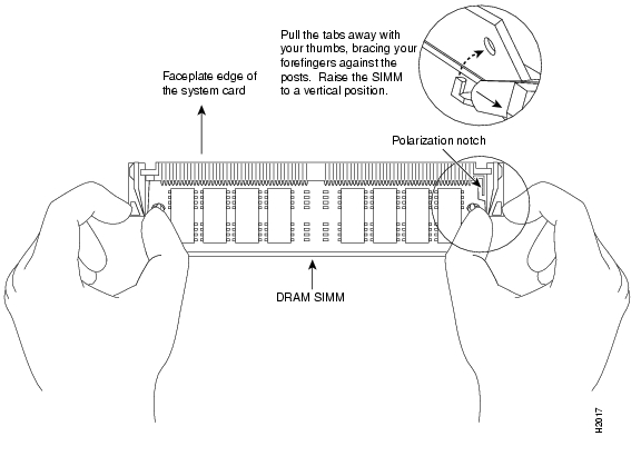
Figure 9-2 Releasing the RSP2 SIMM Spring Clips


Step 1 Turn off the system power and remove the RSP2. (If you have a Cisco 7507 or Cisco 7507-MX, see the procedure in Figure 3-8; if you have a Cisco 7513, Cisco 7513-MX, or a Cisco 7576, see the procedure in Figure 3-14.)

Step 2 Place the RSP2 on an antistatic mat or pad, and ensure that you are wearing an antistatic device, such as a wrist strap. Position the RSP2 so that the faceplate is away from you and the edge connector is toward you—the opposite of the position shown in Figure 9-1.

Step 3 Locate the DRAM SIMMs on the RSP2. The SIMMs occupy U33 and U21 in bank 0, and U12 and U4 in bank 1.

Step 4 Release the spring clips from the SIMM you want to remove and release the SIMM from the socket. (See Figure 9-2.)

Step 5 When both ends of the SIMM are released from the socket, grasp the ends of the SIMM with your thumb and forefinger and pull the SIMM completely out of the socket. Handle the edges of the SIMM only; avoid touching the memory module or pins and the metal traces (the metal fingers along the connector edge of the SIMM) along the socket edge.

Step 6 Place the SIMM in an antistatic bag to protect it from ESD damage. You can use the SIMMs that you remove in compatible equipment.

Step 7 Repeat Step 4 through Step 6 for the remaining SIMMs, as required for your upgrade.


This completes the SIMM removal procedure.

Proceed to the next section to install the new SIMMs.

Installing New RSP2 SIMMs

This section describes the procedure for installing new RSP2 SIMMs.


Caution SIMMs are sensitive components that can be shorted by mishandling, and they are susceptible to ESD damage. Handle SIMMs by the edges only; avoid touching the memory modules, pins, or traces.

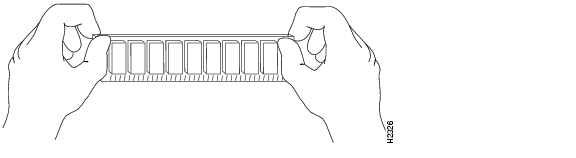
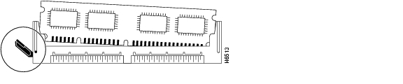
Figure 9-3 Handling an RSP2 SIMM

Use the following procedure to install the new SIMMs:


Step 1 Ensure that the RSP2 is in the same orientation as the preceding procedure (with the handle away from you and the edge connector toward you).

Step 2 Remove a new SIMM from the antistatic bag.

Step 3 Hold the SIMM component-side up, with the connector edge (the metal fingers) closest to you. Hold the sides of the SIMM between your thumb and middle finger, with your forefinger against the far edge, opposite the connector edge.

Step 4 Tilt the SIMM to approximately the same angle as the socket and insert the entire the connector edge into the socket. (Install the first SIMM in the slot farthest away from you. Install the last SIMM in the slot closest to you.)


Caution When inserting SIMMs, use firm but not excessive pressure. If you damage a socket, you will have to return the RSP2 to the factory for repair.

Step 5 Gently push the SIMM into the socket until the spring clips snap over the ends of the SIMM. If necessary, rock the SIMM gently back and forth to seat it properly.

Step 6 Repeat Step 2 through Step 5 for the remaining SIMMs.

Step 7 When all SIMMs are installed, check all alignment holes (two on each SIMM) to ensure that the spring retainer is visible. If it is not, the SIMM is not seated properly. If any SIMM appears misaligned, carefully remove it and reseat it in the socket. Push the SIMM firmly back into the socket until the retainer springs snap into place.

Step 8 Replace the RSP2. (If you have a Cisco 7507 or Cisco 7507-MX, see the procedure in Figure 3-8; if you have a Cisco 7513, Cisco 7513-MX, or a Cisco 7576, see the procedure in Figure 3-14.)

Step 9 Turn on power to the system.


After you have correctly installed RSP2 DRAM SIMMs, reinstalled the RSP2, and turned on the system power, the system should reboot properly.

If the system fails to boot properly, or if the console terminal displays a checksum or memory error, check the following:

Ensure that all SIMMs are installed correctly. If necessary, shut down the system and remove the RSP2. Check the SIMMs by looking straight down on them to inspect them at eye level. The SIMMs should all be aligned at the same angle and the same height when properly installed. If a SIMM appears to stick out or rest in the socket at a different angle from the others, remove the SIMM and reinsert it. Then replace the RSP2 and reboot the system for another installation check.

Each DRAM SIMM bank must contain SIMMs of the same size and speed or the system will not operate. SIMMs must be 60 ns or faster. The speed is printed along one edge of the SIMM.

If after several attempts the system fails to restart properly, contact a service representative for assistance. Before you call, make note of any error messages, unusual LED states, or any other indications that might help solve the problem.


Note The time required for the system to initialize varies with different router configurations. Routers with 128 MB of DRAM will take longer to boot than those with 16 MB of DRAM.


This completes the DRAM SIMM replacement procedure for the RSP2.

Upgrading or Replacing DRAM DIMMs on the RSP4 and RSP8

This section describes the procedures for replacing up to two dual in-line memory modules (DIMMs) on your RSP4 or RSP8. You obtain the DIMMs from Cisco Systems.

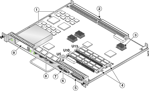
The system DRAM resides in up to two DIMM sockets in two memory banks, 0 and 1. The DRAM DIMM sockets on the RSP4 are U10 (bank 0) and U13 (bank 1). The default DRAM configuration is 32 MB (one 32-MB DIMM in U10). The DRAM DIMM sockets on the RSP8 are U12 (bank 0) and U15 (bank 1). The default DRAM configuration is 64 MB (two 32-MB DIMMs or one 64-MB DIMM).


Caution To prevent system problems, do not use DRAM SIMMs from an RSP2 in the RSP4 or RSP8. The RSP4 and RSP8 require DRAM DIMMs.


Note The total number of memory devices per DIMM differs for each manufacturer. The DIMMs in the following illustrations are generic representations of the actual DRAM DIMMs for your RSP4 or RSP8. To ensure that you are using the correct DIMMs, refer to the specific part or product numbers indicated by your DRAM upgrade requirements, or to the Cisco part numbers on the DIMMs. DRAM upgrades require the removal of the RSP4 or RSP8, so plan your DRAM upgrade to minimize your system downtime.


Figure 9-4 RSP4 DRAM DIMM Locations

1

MEMD SRAM

6

Flash EPROM (ROMmon) U5

2

Bus connector

7

Auxiliary port

3

CPU

8

Flash memory SIMM holder

4

DRAM DIMMs (bank 0: bottom) U10
DRAM DIMMs (bank 1: top)       U13

9

PC Card slot 0: bottom
PC Card slot 1: top

(For Flash memory cards)

5

Console port


Note Each RSP4 DIMM socket has one plastic lever on one end, which is used to remove the DIMM from its socket.


Caution To prevent memory problems, DRAM DIMMS must be 3.3V devices. Do not attempt to install higher-voltage devices (such as those designed for the RSP2) in the RSP4 DIMM sockets.

Figure 9-5 RSP8 DRAM DIMM Locations

1

MEMD SRAM

6

Flash EPROM (ROMmon)

2

Bus connectors

7

Auxiliary port

3

CPU

8

Flash memory SIMM holder

4

DRAM DIMMs (bank 0: bottom)
DRAM DIMMs (bank 1: top)

9
PC Card slot 0: bottom
PC Card slot 1: top

(for Flash Disks or Memory Cards

5

Console port


Note Each RSP8 DIMM socket has one plastic lever on one end, which is used to remove the DIMM from its socket.


Caution To prevent memory problems, DRAM DIMMS must be 3.3V devices. Do not attempt to install higher-voltage devices (such as those designed for the RSP2) in the RSP8 DIMM sockets.

Table 9-2 lists the various configurations of DRAM DIMMs that are available for the RSP4 and Table 9-3 lists the various configurations of DRAM DIMMs that are available for the RSP8. These tables also provide the number of DIMMs for each configuration, and the DRAM banks they occupy. Note which banks are used given the combinations of available DIMM sizes and the maximum DRAM you require.


Note Depending on your router configuration and the protocols and features your system is running, you might require more than the 32 MB of default DRAM for your RSP4, and more than the 64 MB of default DRAM for your RSP8. Upgrade your system DRAM based on your current configuration, this potential requirement, and the information in Table 9-2 and Table 9-3 .


Table 9-2 DRAM DIMM Configurations for the RSP4 

Quantity
Totals
Product Numbers

One 32-MB DIMM

32 MB

MEM-RSP4-32M1

One 32-MB DIMM

32 MB

MEM-RSP4-32M=2

Two 32-MB DIMMs or one 64-MB DIMM3

64 MB

MEM-RSP4-64M=

One 128-MB DIMM

128 MB

MEM-RSP4-128M=

Two 128-MB DIMMs

256 MB

MEM-RSP4-256M=

1 The 32-MB DRAM configuration is the default for RSP4s shipped in a Cisco 7507, Cisco 7513, and
Cisco 7576 router.

2 This DRAM product spare option assumes you already have one 32-MB DRAM DIMM installed in an RSP4 and want to upgrade to 64 MB of DRAM by adding a second 32-MB DRAM DIMM.

3 When using the MEM-RSP4-64M= Product Number to order spare DRAM, note that two 32-MB DIMMs are currently shipped. As DRAM supplies warrant, these orders may be fulfilled with one 64-MB DIMM in the future.


Table 9-3 DRAM DIMM Configurations for the RSP8 

Quantity
Totals
Product Numbers

One 64-MB DIMM1

64 MB

MEM-RSP8-64M2

One 128-MB DIMM

128 MB

MEM-RSP8-128M=

Two 128-MB DIMMs

256 MB

MEM-RSP8-256M=

1 When using the MEM-RSP8-64M= Product Number to order spare DRAM, note that two 32-MB DIMMs are currently shipped. As DRAM supplies warrant, these orders may be fulfilled with one 64-MB DIMM in the future.

2 The 64-MB DRAM configuration is the default for RSP8s shipped in a Cisco 7507-MX and Cisco 7513-MX router. Order this DRAM if you already have 64MB of DRAM in one DIMM socket and want to upgrade to 128 MB of DRAM by adding 64 MB of DRAM in the other DIMM socket.


Caution To prevent system and memory problems when installing DRAM, the RSP4 and RSP8 DRAM DIMMS must be 3.3V devices. Do not attempt to install higher-voltage devices (such as those designed for the RSP2) in the RSP4 or RSP8 DIMM sockets.

To prevent system and memory problems, use the same size and type Cisco DIMM in each socket. If you have a redundant RSP in the system, the memory size and type on the redundant RSP must be the same as the memory size and type on the primary RSP.

Removing RSP4 and RSP8 DIMMs

This section describes the procedure for removing RSP4 and RSP8 DIMMs.

If you are upgrading from 64 MB to 256 MB, you must replace both DRAM DIMMs; therefore, the following procedure is required; however, this procedure is not required if you want to add one DIMM to a DRAM configuration that uses only one DIMM. For example, if you want to upgrade from 32 MB to 64 MB or from 128 MB to 256 MB, you need to add one DRAM DIMM to U13 (RSP4) or U15 (RSP8); therefore, proceed to the section "Installing New RSP4 or RSP8 DIMMs" section.


Caution To prevent ESD damage, handle DIMMs by the card edges only.

Use the following procedure to remove the existing DIMMs:


Step 1 Turn off the system power and remove the RSP4 or RSP8. (If you have a Cisco 7505, see the procedure in Figure 3-3; if you have a Cisco 7507 or 7507-MX, see the procedure in Figure 3-8; if you have a Cisco 7513, Cisco 7513-MX, or a Cisco 7576, see the procedure in Figure 3-14.)

Step 2 Place the RSP4 or RSP8 on an antistatic mat or pad and ensure that you are wearing an antistatic device, such as a wrist strap.

Step 3 Position the RSP4 or RSP8 so that the faceplate is toward you and the edge connector is away from you .

Step 4 Locate the DRAM DIMMs on the RSP4 or RSP8. The DIMMs occupy U10 bank 0 and U13 bank 1 (RSP4), and U12 bank 0 and U15 bank 1 (RSP8).

Step 5 For the DIMM you want to remove, pull down the lever on the DIMM socket to release the DIMM from the socket.

Figure 9-6 Using the RSP4 or RSP8 DIMM Socket Release Lever to Remove DIMMs

Step 6 When one end of the DIMM is released from the socket, grasp each end of the DIMM with your thumb and forefinger and pull the DIMM completely out of the socket. Handle the edges of the DIMM only; avoid touching the memory module or pins and the metal traces (the metal fingers along the connector edge of the DIMM) along the socket edge.

Step 7 Place the DIMM in an antistatic bag to protect it from ESD damage. You can use the DIMMs that you remove in other compatible equipment.

Step 8 Repeat Step 4 through Step 7 for the remaining DIMM if required for your upgrade.


This completes the DIMM removal procedure. Proceed to the next section to install the new DIMMs.

Installing New RSP4 or RSP8 DIMMs

This section describes the procedure for installing new RSP4 or RSP8 DIMMs.


Note If you are upgrading from 32 MB to 64 MB or from 128 MB to 256 MB, you need to add one DRAM DIMM to U13 (RSP4), or U15 (RSP8); therefore, the following procedure is required. Use the following procedure to install the new DIMMs:


Step 1 Place the RSP4 or RSP8 on an antistatic mat or pad, and ensure that you are wearing an antistatic device, such as a wrist strap.

Step 2 Position the RSP4 or RSP8 so that the faceplate is toward you and the edge connector is away from you—this position is shown in Figure 9-4 for the RSP4 and Figure 9-5 for the RSP8.


Caution DIMMs are sensitive components that can be shorted by mishandling; they are susceptible to ESD damage. Handle DIMMs by the edges only; avoid touching the DIMMs, pins, or traces.

Step 3 Remove the new DIMM from the antistatic bag.

Step 4 Hold the DIMM component-side up, with the connector edge (the metal fingers) closest to you. Hold the ends of the DIMM between your thumb and forefinger.

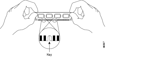
Figure 9-7 Handling an RSP4 or RSP8 DIMM

Step 5 Tilt the DIMM to approximately the same angle as the socket and insert the connector edge into the socket. Note the two notches (keys) on the connector edge of the DIMM. These keys are intended to ensure correct orientation of the DIMM in the socket.


Caution When inserting DIMMs, use firm but not excessive pressure. If you damage a socket, you will have to return the RSP4 or RSP8 to the factory for repair.

Step 6 Note the orientation of the socket key on the DIMM and the DIMM socket and gently push the DIMM into the socket until the lever is flush against the side of the DIMM socket, and the DIMM edge connector is fully inserted. If necessary, rock the DIMM gently back and forth to seat it properly.

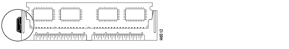
Figure 9-8 Installing an RSP4 or RSP8 DRAM DIMM in the Socket

Step 7 When the DIMM is installed, check that the release lever is flush against the side of the DIMM socket. If it is not, the DIMM might not be seated properly. If the DIMM appears misaligned, carefully remove it according to the removal procedure, and reseat it in the socket. Push the DIMM firmly back into the socket until the release lever is flush against the side of the DIMM socket.

Step 8 Repeat Step 3 through Step 7 for the remaining DIMM, as required for your DRAM configuration.

Step 9 Replace the RSP4 or RSP8. If you have a Cisco 7505, see the procedure in Figure 3-3; if you have a Cisco 7507 or Cisco 7507-MX, see the procedure in Figure 3-8; if you have Cisco 7513, Cisco 7513-MX, or a Cisco 7576, see the procedure in Figure 3-14.)

Step 10 Turn on power to the system.


After you have correctly installed RSP4 or RSP8 DRAM DIMMs and reinstalled the RSP4 or RSP8, and turned on the system power, the system should reboot properly.

If the system fails to boot properly or if the console terminal displays a checksum or memory error after you have installed new DIMMs, check the following:

Ensure that all DIMMs are installed correctly. If necessary, shut down the system and remove the RSP4 or RSP8. Check the DIMMs by looking straight down on them to inspect them at eye level. The DIMMs should all be aligned at the same angle and the same height when properly installed. If a DIMM appears to stick out or rest in the socket at a different angle from the others, remove the DIMM and reinsert it. Then replace the RSP4 or RSP8 and reboot the system for another installation check.

In DRAM configurations with two DRAM DIMMs, both banks must contain DIMMs of the same size and speed, or the system will not operate. DIMMs must be 60 ns or faster. The speed is printed along one edge of the DIMM.

If after several attempts the system fails to restart properly, contact a service representative for assistance. Before you call, make note of any error messages, unusual LED states, or any other indications that might help solve the problem.


Note The time required for the system to initialize might vary with different router configurations and DRAM configurations. Routers with 256 MB of DRAM might take longer to boot than those with less DRAM.


This completes the DRAM DIMM replacement procedure for the RSP4 and RSP8.


hometocprevnextglossaryfeedbacksearchhelp

Posted: Thu Mar 24 11:46:07 PST 2005
All contents are Copyright © 1992--2005 Cisco Systems, Inc. All rights reserved.
Important Notices and Privacy Statement.