|
|

Table Of Contents
Performing a Basic Configuration of the System
Starting the System and Observing Initial Conditions
Overview of Software Configuration Register Settings at Startup
Configuring the Software Configuration Register
Configuration Register Bit Meanings
Changing Configuration Register Settings
Booting the Cisco 7500 Series Router for the First Time
Using the Enable Secret and the Enable Password
Configuring the Cisco 7500 Series System
Performing a Basic Configuration Using AutoInstall
Performing a Basic Manual Configuration Using the Setup Facility
Performing a Basic Configuration Using Configuration Mode
Saving the Settings to NVRAM and Reviewing Your Configuration
Implementing Other Configuration Tasks
Using the Flash Memory Cards in the RSPs
Installing and Removing a Flash Memory Card in an RSP
Formatting a Flash Memory Card
Making a Flash Memory Card Image Bootable
Enabling Booting from Flash Memory
Additional Commands Associated with Flash Memory
Additional Procedures Associated with Flash Memory Cards
If You Need More Configuration Information
Performing a Basic Configuration of the System
This chapter describes the procedures for performing a basic configuration of your Cisco 7500 series router. It guides you through a basic router configuration, which is sufficient for you to access your network. Complex configuration procedures are beyond the scope of this text, and can be found in the configuration publications listed in the "If You Need More Configuration Information" section.
Note
The Cisco IOS command examples in this chapter are from Release 11.1(8)CA. The examples might appear differently on your system depending on the Cisco IOS software release in use, and the router model being configured. If you are using an RSP8, note that it is only compatible with specific Cisco IOS 12.0 releases, examples of which are not included in this guide. Refer to the Route Switch Processor (RSP8) Installation and Configuration Guide for specific information on configuring a router equipped with an RSP8. When configuring a Cisco 7576, you will configure router A and then router B.
The following sections provide information for configuring your Cisco 7500 series router:
•
•
•
•
•
•
•
•
•
To configure a Cisco 7500 series router from a console, you need to connect a terminal to the router's console port. Configuration requires access to the console port on each Route Switch Processor (RSP) in your router.
Note
Starting the System and Observing Initial Conditions
This section describes the initial Cisco 7500 series system startup.
When all interfaces are connected, perform a final check of all connections and then power up the router as follows:
Step 1
•
•
•
•
Step 2
Step 3
Step 4
Step 5
Step 6
Step 7
The enabled LED on each interface processor goes on when initialization has been completed, and the console screen displays a script and system banner similar to the following:
GS Software (RSP-K ), Version 11.1(8)CACopyright (c) 1986-1995 by Cisco Systems, Inc.This RSP2 is system masterOther RSP2 is not plugged inCompiled Wed 10-May-95 11:06Step 8
--- System Configuration Dialog ---At any point you may enter a questions mark `?' for help.Refer to the `Getting Started' Guide for additional help.Default settings are in square brackets `[]'. continue withconfiguration dialog? [yes]:You have the option of proceeding with the setup facility to configure the interfaces, or exit from setup and use configuration commands to configure global (system-wide) and interface-specific parameters. You do not have to configure the interfaces immediately; however, you cannot enable the interfaces or connect them to any networks until you have configured them.
Many of the interface processor LEDs will not go on until you have configured the interfaces. To verify correct operation of each interface, complete the first-time startup procedures and configuration, and then refer to the LED descriptions in the companion publication Interface Processor Installation and Configuration Guide to check the status of the interfaces.
If the system does not complete each of these steps, proceed to "Troubleshooting a Cisco 7500 Series Router," for troubleshooting recommendations and procedures.
Overview of Software Configuration Register Settings at Startup
Bits 0 through 3 of the software configuration register form the boot field, specified as a binary number. The factory default configuration register setting for systems is 0x102; for RSP spares the default is 0x101.
When the boot field is set to either 0 or 1 (0-0-0-0 or 0-0-0-1), the system ignores any boot instructions in the system configuration file and the following occurs:
•
•
You can enter the boot command only, or include additional boot instructions with the command, such as the name of a file stored in Flash memory or a file that you specify for booting from a network server. If you use the boot command without specifying a file or any other boot instructions, the system boots from the default Flash image (the first image in onboard Flash memory). Otherwise, you can instruct the system to boot from a specific Flash image (using the boot system flash filename command), or boot from a network server by sending broadcast TFTP requests (using the boot system filename command), or by sending a direct TFTP request to a specific server (using the boot system filename address command).
You can also use the boot command to boot images stored in the PC Card Flash memory cards in the RSP. If you set the boot field to any bit pattern other than 0 or 1, the system uses the resulting number to form a filename for booting over the network.
The system uses the filename to invoke the system image by booting over the net. However, if the configuration file contains any boot instructions, the system uses those boot instructions instead of the filename it computed from the configuration register settings. You must set the boot field for the boot functions you require.
For more detailed information on the software configuration register features, see the next section, " Configuring the Software Configuration Register." For information on the boot command and function, see the "Booting the Cisco 7500 Series Router for the First Time" section.
Configuring the Software Configuration Register
Note
Cisco 7500 series routers use a 16-bit software configuration register, which allows you to set specific system parameters. Settings for the software configuration register are written into NVRAM.
Following are some reasons for changing the software configuration register settings:
•
•
•
•
•
•
•
•
•
Table 4-1 lists the meaning of each of the software configuration memory bits, and Table 4-2 defines the boot field.
Caution
Table 4-1 Software Configuration Register Bit Meanings
00 to 03
0x0000 to 0x000F
Boot field
06
0x0040
Causes system software to ignore NVRAM contents
07
0x0080
OEM2 bit enabled
08
0x0100
Break function disabled
09
0x0200
Use secondary bootstrap
10
0x0400
Internet Protocol (IP) broadcast with all zeros
11 to 12
0x0800 to 0x1000
Console line speed (default is 9600 baud)
13
0x2000
Boot default Flash software if network boot fails
14
0x4000
IP broadcasts do not have network numbers
15
0x8000
Enable diagnostic messages and ignore NVRAM contents
1 The factory default value for the configuration register is 0x0101.
This value is a combination of the following: bit 8 = 0x0100 and bits 00 through 03 = 0x0001.2 OEM = original equipment manufacturer.
Configuration Register Bit Meanings
The lowest four bits of the software configuration register (bits 3, 2, 1, and 0) form the boot field. The boot field specifies a number in binary form. If you set the boot field value to 0, you must boot the operating system manually by entering the b command at the bootstrap prompt (>), as follows:
> b [tftp] flash filenameDefinitions of the various b command options follow:
•
•
•
•
•
•
For more information about the b [tftp | flash ] [filename] command, refer to the set of configuration fundamentals publications listed in the "If You Need More Configuration Information" section.
If you set the boot field value to 0x2 through 0xF and there is a valid boot system command stored in the configuration file, the router boots the system software as directed by that value. If there is no boot system command, the router forms a default boot filename for booting from a network server. (See Table 4-3 for the format of these default filenames.)
In the following example, the software configuration register is set to boot the router from onboard Flash memory and to ignore the Break function at the next reboot of the router:
Router# conf termEnter configuration commands, one per line. End with CNTL/Z.Router(config)# config-register 0x102Router(config)# boot system flash [filename]Crtl-ZRouter#Table 4-3 lists the default boot filenames or actions for the processor.
Note
Bit 8 controls the console Break key. Setting bit 8 (the factory default) causes the processor to ignore the console Break key. Clearing bit 8 causes the processor to interpret the Break key as a command to force the system into the bootstrap monitor, thereby halting normal operation. Regardless of the setting of the break enable bit, a break will cause a return to the ROM monitor during the first few seconds (approximately 5 seconds) of booting.
Bit 9 is unused. Bit 10 controls the host portion of the IP broadcast address. Setting bit 10 causes the processor to use all zeros; clearing bit 10 (the factory default) causes the processor to use all ones. Bit 10 interacts with bit 14, which controls the network and subnet portions of the broadcast address.
Table 4-4 shows the combined effect of bit 10 and bit 14.
Table 4-4 Configuration Register Settings for Broadcast Address Destination
Off
Off
<ones> <ones>
Off
On
<zeros> <zeros>
On
On
<net> <zeros>
On
Off
<net> <ones>
Bit 11 and bit 12 in the configuration register determine the data transmission rate of the console terminal. Table 4-5 shows the bit settings for the four available rates. (The factory-set default data transmission rate is 9600.)
Table 4-5 Console Terminal Transmission Rates
9600
0
0
4800
0
1
2400
1
1
1200
1
0
Bit 13 determines the server response to a bootload failure. Setting bit 13 causes the server to load operating software from Flash memory after five unsuccessful attempts to load a boot file from the network. Clearing bit 13 causes the server to continue attempting to load a boot file from the network indefinitely. By factory default, bit 13 is cleared to 0.
Changing Configuration Register Settings
To change the configuration register while running the system software, follow these steps:
Step 1
Router> enablePassword:router#Step 2
Router# conf tEnter configuration commands, one per line. End with CNTL/Z.Router(config)#Step 3
Router(config)# config-register 0xvalueStep 4
Step 5
Step 6
Configuration register is 0x141 (will be 0x101 at next reload)Step 7
Booting the Cisco 7500 Series Router for the First Time
The router is administered using the Cisco command interpreter, called the EXEC. You must boot and log in to the router before you can enter an EXEC command. For security purposes the EXEC has two levels of access to commands: user EXEC mode and privileged EXEC mode.
To enter the privileged mode you must enter the enable secret password (which is optional, but must first have been saved in memory) on systems running Cisco IOS Release 10.2(3) or later, or the enable password on systems running Cisco IOS releases prior to Release 10.2(3) or when using the boot ROM software. At the ROM monitor prompt, view what is in onboard Flash memory using the following command (the Cisco IOS software image name shown is used as an example only):
rommon 1> dir bootflash:File size Checksum File name3277967 bytes (0x32048f) 0x6b331e30 rsp-jv-mz.111-8rommon 2>Also, you can view contents of the Flash memory PC Card in slot 0 or slot 1 using the following command (the Cisco IOS software image name shown is used as an example only):
rommon 2> dir slot0:File size Checksum File name3054276 bytes (0x2e9ac4) 0x97788495 rsp-jv-mz.111-8rommon 3>Boot from one of the images in Flash memory using the following commands (the Cisco IOS software image name shown is used as an example only):
rommon 3> boot slot0:rsp-jv-mz.111-8rommon 3>boot slot1:rsp-jv-mz.111-8rommon 3>boot bootflash:rsp-jv-mz.111-8If you did not change the configuration register setting, the next reload will revert to the default configuration register setting. The factory default configuration register setting for systems is 0x102; for RSP spares the default is 0x101.
Using the Enable Secret and the Enable Password
The commands available at the user level are a subset of those available at the privileged level. Because many privileged-level EXEC commands are used to set operating parameters, you should password-protect these commands to prevent unauthorized use.
There are two commands you can use to do this, depending on which release of the Cisco IOS software you have:
•
•
The enable and enable secret password functionality is available in all Cisco IOS releases for the Cisco 7500 series routers. You must enter the correct password to gain access to privileged-level commands. When you are running from the boot ROM, the enable password might be used depending on your ROM level.
The passwords should be different for maximum security. If you enter the same password for both during the setup script, the system will accept it, but you will receive a warning message indicating that you should enter a different password.
An enable secret password can contain from 1 to 25 uppercase and lowercase alphanumeric characters; an enable password can contain any number of uppercase and lowercase alphanumeric characters. In both cases, a number cannot be the first character. Spaces are also valid password characters; for example, "two words" is a valid password. Leading spaces are ignored; trailing spaces are recognized.
Recovering a Lost Password
This section provides information on how to recover a lost password. Following is an overview:
•
•
•
Note
•
•
•
To recover a lost password, use the following procedure:
Note
Step 1
Step 2
Step 3
Step 4
Step 5
rommon 1>Step 6
rommon 1> confregConfiguration Summaryenabled are:console baud: 9600boot: image specified by the boot system commandor default to: cisco2-RSPdo you wish to change the configuration? y/n [n]: yenable "diagnostic mode"? y/n [n]:enable "use net in IP bcast address"? y/n [n]:enable "load rom after netbootfails"? y/n [n]:enable "use all zero broadcast"? y/n [n]:enable "break/abort has effect?" y/n [n]:enable "ignore system config info?" [n]: ychange console baud rate? y/n [n]:change boot characteristics? y/n [n]Configuration Summaryenabled are:console baud: 9600boot: image specified by the boot system commandor default to: cisco2-RSPdo you wish to change the configuration? y/n [n]You must reset or power cycle for the new config to take effectStep 7
rommon 1> iThe router will power cycle, the configuration register will be set to ignore the configuration file, and the router will boot the boot system image and prompt you with the system configuration dialog as follows:
--- System Configuration Dialog ---Step 8
Press RETURN to get started!Step 9
Router>Step 10
Router#Step 11
Step 12
Router# configure terminalEnter configuration commands, one per line. End with CNTL/Z.Router(config)#Step 13
Step 14
Step 15
This completes the procedure for recovering a lost password.
Configuring the Cisco 7500 Series System
You can complete a basic configuration of the Cisco 7500 series system using one of the procedures described in the following sections:
•
•
•
Follow the procedure that best fits the needs of your network configuration.
Note
Before continuing the configuration process, check the current state of the router using the show version command. The show version command displays the release of Cisco IOS software that is available on the router.
Performing a Basic Configuration Using AutoInstall
The AutoInstall process is designed to configure the router automatically after connection to your WAN. For AutoInstall to work properly, a TCP/IP host on your network must be preconfigured to provide the required configuration files. The TCP/IP host can exist anywhere on the network, as long as the following two conditions are maintained:
1.
2.
This functionality is coordinated by your system administrator at the site where the TCP/IP host is located. You should not attempt to use AutoInstall unless the required files have been provided on the TCP/IP host. Refer to the appropriate software configuration publications for information on how AutoInstall works.
Use the following procedure to prepare your router for the AutoInstall process:
Step 1
Step 2
The router will load the operating system image from Flash memory. If the remote end of the WAN connection is connected and properly configured, the AutoInstall process will begin.
If the AutoInstall process is completed successfully, you might want to write the configuration data to the router's nonvolatile random-access memory (NVRAM). Perform the following step to complete this task.
Step 3
Hostname# copy running-config startup-configTaking this step saves the configuration settings that the AutoInstall process created in the router. If you fail to do this, your configuration will be lost the next time you reload the router.
Performing a Basic Manual Configuration Using the Setup Facility
If you do not plan to use AutoInstall, do not connect the router's serial (WAN) cable to the CSU/DSU. This prevents the router from attempting to run the AutoInstall process. (The router will attempt to run AutoInstall whenever you start it if the serial [WAN] connection is connected on both ends and the router does not have a configuration stored in NVRAM.) It can take several minutes for the router to determine that AutoInstall is not set up to a remote TCP/IP host.
Once the router has determined that AutoInstall is not configured, it will default to the setup facility. If the serial (WAN) cable is not connected, the router will boot from Flash memory and go into the setup facility.
Note
Configuring the Global Parameters
When you first start the setup program, you must configure the global parameters, which are used for controlling system-wide settings.
Use the following procedure to enter the global parameters:
Step 1
Step 2
System Bootstrap, Version 5.3(16645) [biff 571], RELEASED SOFTWARECopyright (c) 1994-1995 by cisco Systems, Inc.This RSP2 is system masterOther RSP2 is not plugged inRSP2 processor with 16384 Kbytes of main memoryRestricted Rights LegendUse, duplication, or disclosure by the Government issubject to restrictions as set forth in subparagraph(c) of the Commercial Computer Software - RestrictedRights clause at FAR sec. 52.227-19 and subparagraph(c) (1) (ii) of the Rights in Technical Data and ComputerSoftware clause at DFARS sec. 252.227-7013.cisco Systems, Inc.170 West Tasman DriveSan Jose, California 95134-1706Cisco Internetwork Operating System SoftwareIOS (tm) GS Software (RSP-K-MZ), Version 11.1(8), RELEASE SOFTWARE (fc1)Copyright (c) 1986-1995 by cisco Systems, Inc.Compiled Thu 14-Sep-95 19:03 by biffImage text-base: 0x600087E0, data-base: 0x6052A000RSP2 (R4600) processor with 16384K bytes of memory.Manufactured 27-Dec-1995. Blower serial 512.R4600 processor, Implementation 32, Revision 2.0Last reset from power-onG.703/E1 software, Version 1.0.Bridging software.X.25 software, Version 2.0, NET2, BFE and GOSIP compliant.1 EIP controller (2 Ethernet).2 FSIP controllers (4 Serial).2 Ethernet/IEEE 802.3 interfaces.4 Serial network interfaces.Chassis Interface.125K bytes of non-volatile configuration memory.8192K bytes of Flash PCMCIA card at slot 0 (Sector size 128K).8192K bytes of Flash internal SIMM (Sector size 256K).Notice: NVRAM invalid, possibly due to write erase.--- System Configuration Dialog ---At any point you may enter a question mark '?' for help.Refer to the 'Getting Started' Guide for additional help.Use ctrl-c to abort configuration dialog at any prompt.Default settings are in square brackets '[]'.Would you like to enter the initial configuration dialog? [yes]:
Note
Step 3
Would you like to enter the initial configuration dialog? [yes]:First, would you like to see the current interface summary? [yes]:In the following example, the summary shows a router at first-time startup. That is, nothing has been configured, and the summary reflects that fact.
Any interface listed with OK? value "NO" does not have a valid configuration.Interface IP-Address OK? Method Status ProtocolEthernet0/0 unassigned NO not set down downSerial1/0 unassigned NO not set down downStep 4
A typical minimal configuration using IP, IPX, and AppleTalk follows, and continues through Step 10:
Configuring global parameters:Enter host name [Router]: RouterStep 5
The enable secret is a one-way cryptographic secret usedinstead of the enable password when it exists.Enter enable secret: barneyThe enable password is used when there is no enable secretand when using older software and some boot images.Enter enable password: betty
Note
Step 6
Configure SNMP Network Management? [yes]: yesCommunity string [public]:Step 7
Configure CLNS? [no]: noStep 8
Configure AppleTalk? [no]: yesMultizone networks? [no]: yesConfigure IPX? [no]: yesStep 9
Configure Vines? [no]: noConfigure XNS? [no]: noConfigure DECnet? [no]: noConfigure bridging? [no]: noStep 10
Enter yes (the default) or press Return to configure IP, and then select an interior
routing protocol for IP:
Configure IP? [yes]:Configure IGRP routing? [yes]:Your IGRP autonomous system number [1]: 15
Note
Only IP, IPX, and AppleTalk are the selected protocols for this example.Configuring global parameters:Enter host name [Router]:The enable secret is a one-way cryptographic secret usedinstead of the enable password when it exists.Enter enable secret: barneyThe enable password is used when there is no enable secretand when using older software and some boot images.Enter enable password: bettyEnter virtual terminal password: fredConfigure SNMP Network Management? [yes]:Configure AppleTalk? [no]: yConfigure CLNS? [no]:Configure IPX? [no]:Configure Vines? [no]:Configure XNS? [no]:Configure DECnet? [no]:Configure CLNS? [no]:Configure bridging? [no]:Configure IP? [yes]:Configure IGRP routing? [yes]:Your IGRP autonomous system number [15]:Configure Apollo? [no]:Step 11
Configuring Interfaces
This section provides procedures for configuring interfaces to allow communication over a LAN or WAN. To configure the interface parameters, you will need your interface network addresses and subnet mask information; consult your network administrator for this information.
Configuring an Ethernet Interface
Use the following procedure to configure an Ethernet interface:
Step 1
Configuring interface parameters:Configuring interface Ethernet0/0:Is this interface in use? [no]: yesConfigure IP on this interface? [no]: yesIP address for this interface: 10.1.1.10Number of bits in subnet field [0]:Class A network is 10.0.0.0, 0 subnet bits; mask is 255.0.0.0Step 2
Configure IPX on this interface? [no]: yesIPX network number [2]:Step 3
Configure appletalk on this interface? [no]: yesExtended appletalk network? [no]: yesappletalk starting cable range [0]:appletalk zone: zonenameStep 4
Configuring a Synchronous Serial Interface
The synchronous serial interfaces are configured to allow connection to WANs through a CSU/DSU.
Use the following procedure to configure a serial interface:
Step 1
Configuring interface Serial1/0:Is this interface in use? [no]: yesStep 2
Configure IP unnumbered on this interface? [no]:IP address for this interface: 10.1.1.20Number of bits in subnet field [0]:Class A network is 10.0.0.0, 0 subnet bits; mask is 255.0.0.0Configure IPX on this interface? [no]: yesIPX network number [2]:Configure AppleTalk on this interface? [no]: yesExtended AppleTalk network? [no]:AppleTalk network number [1]:Step 3
Note
Only one Ethernet and one synchronous serial interface are configured for this example.Configuring interface parameters:Configuring interface Ethernet0/0:Is this interface in use? [no]: yesConfigure IP on this interface? [no]: yesIP address for this interface: 10.1.1.10Number of bits in subnet field [0]:Class A network is 10.0.0.0, 0 subnet bits; mask is 255.0.0.0Configure IPX on this interface? [no]: yesIPX network number [2]: 10Configure AppleTalk on this interface? [no]: yesExtended AppleTalk network? [no]: yesAppleTalk starting cable range [0]:Configuring interface Serial1/0:Is this interface in use? [no]: yesConfigure IP on this interface? [no]: yesConfigure IP unnumbered on this interface? [no]:IP address for this interface: 10.1.1.20Number of bits in subnet field [0]:Class A network is 10.0.0.0, 0 subnet bits; mask is 255.0.0.0Configure IPX on this interface? [no]: yesIPX network number [2]:Configure AppleTalk on this interface? [no]: yesExtended AppleTalk network? [no]:AppleTalk network number [1]:The following configuration command script was created:hostname Routerenable secret 5 $1$u8z3$PMYY8em./8sszhzk78p/Y0enable password sline vty 0 4password ssnmp-server community publicip routingno vines routingipx routingappletalk routingno apollo routingno decnet routingno xns routingno clns routingno bridge 1! Turn off IPX to prevent network conflicts.interface Ethernet0/0no ipx networkinterface Ethernet0/1no ipx network!interface Ethernet0/0ip address 10.1.1.10 255.0.0.0appletalk cable-range 0-0 0.0appletalk discoveryno mop enabled!interface serial1/0ip address 10.1.1.20 255.0.0.0ip route-cache cbusno keepalive!router igrp 15network 1.0.0.0!endUse this configuration? [yes/no]: yes[OK]Use the enabled mode `configure' command to modify this configuration.Press RETURN to get started!Your Cisco 7500 series router is now minimally configured and ready to use. If you want to modify the parameters after the initial configuration, use the setup command. To perform more complex configurations, use the configure command.
For information on additional interface configuration and information on more specific system configurations, refer to the publications listed in the "If You Need More Configuration Information" section.
Performing a Basic Configuration Using Configuration Mode
You can configure the Cisco 7500 series router manually (through configuration mode) if you prefer not to use the setup facility or AutoInstall.
Use the following procedure to configure the router manually:
Step 1
Step 2
Would you like to enter the initial dialog? [yes]: noStep 3
Router> enableThe prompt will change to the privileged EXEC prompt, as follows:
Router#Step 4
Router# config terminalEnter configuration commands, one per line. End with CNTL/Z.Router(config)#At the Router(config)# prompt, enter the interface type slot/port command to enter interface configuration mode, as follows:
Router(config)#interface serial slot/portRouter(config-if)#When you are in either of these configuration modes, you can enter any changes to the router configuration.
Step 5
Step 6
Your Cisco 7500 series router is now minimally configured and will boot with the configuration you have entered. To see a list of the configuration commands available to you, enter ? at the prompt or press the Help key while in configuration mode.
Checking the Settings
You can check the value of the settings you entered by entering either of the following commands at the # prompt:
•
•
Following is an example:
Router# show running-config...Saving the Settings to NVRAM and Reviewing Your Configuration
To store the configuration or changes to your startup configuration, enter the following commands at the hostname# prompt:
•
•
Following is an example:
Hostname# copy running-config startup-configEntering these commands will save the configuration settings that you created in the router using configuration mode. If you fail to do this, your configuration will be lost the next time you reload the router.
To display information stored in NVRAM, use the show startup-config EXEC command if you are running Cisco IOS Release 11.0 or later, or the show config EXEC command if you are running a Cisco IOS release earlier than Release 11.0.
Implementing Other Configuration Tasks
After you establish the basic startup configuration for your router, if you need to make more advanced configuration changes, see the "If You Need More Configuration Information" section for a list of the appropriate configuration publications.
These publications contain additional information on using the configure command and provide additional information about the following tasks:
•
•
•
•
•
What Do I Do Now?
After you have installed the Cisco 7500 series router hardware, checked all external connections, turned on the system power, allowed the system to boot up, and minimally configured the system, you might need to perform more complete and complex configurations, which are beyond the scope of this text.
For specific information on more complex system and interface configuration and, if necessary, troubleshooting, refer to the publications listed in the "If You Need More Configuration Information" section.
Note
Using the Flash Memory Cards in the RSPs
This section describes procedures for using the Flash memory cards in the RSPs in the Cisco 7500 series routers.
Note
This section includes the following Flash memory card information:
•
•
•
•
•
•
•
For additional Flash memory-related command descriptions and configuration information, refer to the Cisco IOS Configuration Fundamentals Command Reference and the Cisco IOS Configuration Fundamentals Configuration Guide. See the "If You Need More Configuration Information" section for information on obtaining these publications.
You can also refer to the publication Flash Memory Card Installation Instructions (Document Number 78-2083-xx). This publication ships with Flash memory cards shipped as spare parts.
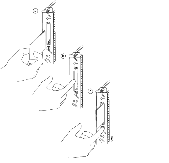
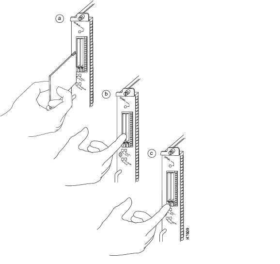
Installing and Removing a Flash Memory Card in an RSP
The RSP has two PC Card slots—slot 0 and slot 1—into which you can install a Flash memory card. In the RSP2, RSP4, and RSP8, the orientation is vertical. PC Card slot 0 is on the left and slot 1 is on the right. (See Figure 4-1 and Figure 4-2).
A Flash memory card can be inserted and removed with the system power on. Both PC Card slots can be used at the same time.
The following procedure is generic, and can be used for a Flash memory card in either slot position.
Use the following procedure to install and remove a Flash memory card:
Step 1
In an RSP2, RSP4, or RSP8, the label should face right, with the Flash memory card positioned as shown in Figure 4-1 or Figure 4-2.
Note
Step 2
Step 3
Step 4
Step 5
Figure 4-1 Installing and Removing a Flash Memory Card (RSP2)
Figure 4-2 Installing and Removing a Flash Memory Card (RSP4/4+ and RSP8)
The following sections include additional procedures for using Flash memory and Flash memory cards.
The following procedures are required if you do not plan to use the Flash memory card as it was shipped to you:
•
•
•
•
The following information is included for reference:
•
•
Formatting a Flash Memory Card
A Flash memory card that shipped with your chassis contains the Cisco IOS software image you need to boot your router. You do not need to reformat it.
In some cases, you might need to insert a new Flash memory card and copy images or back up configuration files onto it. Flash memory cards shipped as spare parts are shipped unformatted and blank. Before you can use a new blank Flash memory card, you must format it. Use only Intel Series 2+ Flash memory cards.
Note
Currently the Cisco IOS release required for Flash memory card compatibility with all RSPs is Cisco IOS Release 11.1(8)CA1 or a later release of 11.1 CA.
Caution
Caution
Use the following procedure to format a new Flash memory card (the procedure assumes you have already booted your router):
Step 1
Step 2
Router# format slot0:All sectors will be erased, proceed? [confirm]Enter volume id (up to 30 characters): MyNewCardFormatting sector 1Format device slot0 completedRouter#
Note
The new Flash memory card is now formatted and ready to use.
Copying Files to Flash Memory
You might need to copy a new image file to Flash memory whenever a new Cisco IOS software release or maintenance release becomes available.
Caution
We recommend that you upgrade Cisco IOS software images in Flash memory one at a time; do not delete all known-good images at one time. Also, upgrade PC Card-based Flash memory separately from onboard Flash memory, to avoid losing important Cisco IOS software images that are known to be good. (The onboard Flash memory is referred to as the bootflash.)
Use the command copy tftp:filename [bootflash | slot0 | slot1]: filename for the copy procedure, where tftp:filename is the source of the file and [ bootflash | slot0 | slot1]: filename is the destination in onboard Flash memory or on either of the Flash memory cards.
An example of the copy tftp:filename command follows for a file in the Flash memory card in PC Card slot 0:
Router# copy tftp:myfile1 slot0:myfile120575008 bytes available on device slot0, proceed? [confirm]Address or name of remote host [10.1.1.1]?Loading new.image from 10.1.1.1 (via Ethernet1/0): !!!!!!!!!!!!!!!!!!!!!!!!!!!!!!!!!!!!!!!!!!!!!!!!!!!!!!!!!!!!!!!!!!!!!!!!!!!!!!!!!!!!!!!!!!!!!!!!!!!!!!!!!!!!![OK - 7799951/15599616 bytes] CCCCCCCCCCCCCCCCCCCCCCCCCCCCCCCCCCCCCCCCCCCCCCCCCCCCCCCCCCCCCCCCCCCCCCCCCCCCCCCCCCCCCCCCCCCCCCCCCCCCCCCCCCCCCCCCCCCCCCCCCCCCCCCCCCCCCCCCCCCCCCCCCCCCCCCCCCCCCCCRouter#
Note
Making a Flash Memory Card Image Bootable
Use the following series of commands to make a Flash memory card image bootable. (In this example, the filename is new.image.) Note that the config-register command is part of the sequence because the configuration register must be set to 0x2102 to enable loading an image from Flash memory.
Router# config terminalRouter(config)# no boot systemRouter(config)# boot system flash slot0:new.imageRouter(config)# config-register 0x2102Crtl-ZRouter# copy running-config startup-configRouter# reloadWhen the system reloads, it will boot the image new.image from the Flash memory card in slot 0.
Enabling Booting from Flash Memory
To enable booting from Flash memory, set configuration register bits 3, 2, 1, and 0 to a value between 2 and 15 in conjunction with the boot system flash device:filename configuration command, where device is bootflash:, slot0:, or slot1:, and filename is the name of the file from which you want to boot the system. (For detailed configuration register information, see the "Configuring the Software Configuration Register" section.)
To enter configuration mode while in the system software image and specify a Flash filename from which to boot, enter the configure terminal command at the enable prompt, as follows:
Router# configure terminalEnter configuration commands, one per line. End with CNTL/Z.Router(config)# boot system flash device:filenameTo disable the Break function and enable the boot system flash device:filename command, enter the config-register command with the value shown in the following example:
Router(config)# config-reg 0x0100Crtl-ZRouter#Additional Commands Associated with Flash Memory
This section describes additional commands related to using the onboard Flash memory (bootflash) on the RSP and the Flash memory cards (PC Card slot 0 and slot 1). The following examples assume you have Flash memory cards in PC Card slot 0 and slot 1.
You can determine which memory media you are accessing using the pwd command, as follows:
Router# pwdslot1You can move between Flash memory media using the cd [bootflash | slot0 | slot1] command, as follows:
Router# cd slot0slot0Router# cd slot1Router# pwdslot1You can list the directory of Flash memory media using the dir [bootflash | slot0 | slot1] command, as follows:
Router# dir-#- -length- -----date/time------ name1 4601977 May 10 1996 09:42:19 myfile16 679 May 10 1996 05:43:56 todays-config7 1 May 10 1996 09:54:53 fun1You can delete a file from any Flash memory media using the delete [bootflash | slot0 | slot1]:filename command, as follows:
Router# delete slot0:fun1Router# dir-#- -length- -----date/time------ name1 4601977 May 10 1996 09:42:19 myfile1Files that are deleted are marked as deleted, but still occupy space in Flash memory. The squeeze command removes them permanently and pushes all other undeleted files together to eliminate spaces between them.
Following is the syntax of the squeeze command:
Router# squeeze slot0:All deleted files will be removed, proceed? [confirm]Squeeze operation may take a while, proceed? [confirm]ebESZTo prevent loss of data due to sudden power loss, the "squeezed" data is temporarily saved to another location of Flash memory, which is specially used by the system.
In the preceding command display output, the character "e" means this special location has been erased (which must be performed before any write operation). The character "b" means that the data that is about to be written to this special location has been temporarily copied. The character "E" signifies that the sector that was temporarily occupied by the data has been erased. The character "S" signifies that the data was written to its permanent location in Flash memory. The squeeze command operation keeps a log of which of these functions has been performed so in case of a sudden power failure, it can come back to the right place and continue with the process. The character "Z" means this log was erased after the successful squeeze command operation.
The configuration register setting 0x0101 tells the system to boot the default image (the first image) from onboard Flash memory, but not reset the Break function disable or check for a default filename to be booted over the network. The configuration register setting 0x0102 tells the system to boot from Flash memory if a network boot fails, disable the Break function, and check for a default filename to boot over the network.
For more information on the copy tftp:filename [flash | slot0 | slot1]:filename command, and other related commands, refer to the set of configuration fundamentals configuration and reference publications listed in the "If You Need More Configuration Information" section.
Additional Procedures Associated with Flash Memory Cards
This section describes additional procedures that can be used with Flash memory cards but are not always required.
Copying a Bootable Image into a Flash Memory Card
You can copy a bootable image into Flash memory; however, you must first format the Flash memory card and make the image in the Flash memory card bootable. (If you have not already done these tasks, see the "Formatting a Flash Memory Card" section and the "Making a Flash Memory Card Image Bootable" section.)
To copy an image, use the following procedure, which assumes:
•
•
•
To ensure access to a TFTP server, you need to configure at least one interface using the setup facility. For instructions on using this procedure, refer to the Configuration Fundamentals Configuration Guide publication.
•
Following is the procedure for copying a bootable file (called new.image) into the Flash memory card:
Step 1
Note
Caution
Step 2
Router> enPassword:Router# copy tftp:new.image slot0:new.image20575008 bytes available on device slot0, proceed? [confirm]Address or name of remote host [1.1.1.1]?Loading new.image from 1.1.1.1 (via Ethernet1/0): !!!!!!!!!!!!!!!!!!!!!!!!!!!!!!!!!!!!!!!!!!!!!!!!!!!!!!!!!!!!!!!!!!!!!!!!!!!!!!!!!!!!!!!!!!!!!!!!!!!!!!!!!!!!![OK - 7799951/15599616 bytes] CCCCCCCCCCCCCCCCCCCCCCCCCCCCCCCCCCCCCCCCCCCCCCCCCCCCCCCCCCCCCCCCCCCCCCCCCCCCCCCCCCCCCCCCCCCCCCCCCCCCCCCCCCCCCCCCCCCCCCCCCCCCCCCCCCCCCCCCCCCCCCCCCCCCCCCCCCCCCCCCCCCCCCCCCCCCCCCCCCCCCCCCCCRouter#In the preceding example, the exclamation points (!!!) appear as the file is downloaded, and the "C" characters signify calculation of the cyclic redundancy check (CRC) value, which is a verification that the file has been correctly downloaded to the Flash memory card.
This completes the procedure for copying a bootable image into a Flash memory card.
Copying Bootable Images Between Flash Memory Cards
As future releases of Cisco IOS images become available, you will receive these images either as a file booted from a network server, a file on a floppy disk, or a file on a Flash memory card.
The following scenario describes how to use a newly released image on a Flash memory card in a system that has an older image on a Flash memory card in slot 0 and a default boot image in the onboard Flash memory.
For this scenario, the filenames are as follows:
•
•
•
You will copy the new image from the new Flash memory card onto the Flash memory card that contains the old image.
Note
Following is the procedure for copying bootable images between Flash memory cards:
Step 1
Step 2
Router> enPassword:Router#Step 3
Step 4
Router# copy slot1:image.new slot0:image.newThe previous command can also be entered as copy slot1:image.new slot0:.
Step 5
Router# config tRouter(config)# no boot systemRouter(config)# boot system flash slot0:image.newCrtl-ZRouter# copy running-config startup-configRouter# reloadWhen the system reloads, it will boot the file image.new from the Flash memory card in slot 0.
This completes the procedure for copying bootable images between Flash memory cards.
Copying Files Between RSP Memory and a Flash Memory Card
Copying a configuration file to a Flash memory card in PC Card slot 0 or slot 1 might be required if you do not have access to a TFTP server on which you can temporarily store your configuration file. You can then copy the configuration file back to NVRAM at any time. Use the procedures in the following sections to first copy the configuration file from NVRAM or DRAM to a Flash memory card, and then to copy the configuration from the Flash memory card back to NVRAM.
Copying a Configuration File from RSP NVRAM to a Flash Memory Card on the RSP
You can use the command copy startup-config [slot0: | slot1:]:filename for the copy procedure, in which startup-config is the file source (NVRAM) and [slot0: | slot1:]:filename is the file's destination in either of the Flash memory cards; note that the environmental variable CONFIG_FILE must be pointing (set) to NVRAM, which is the system default.
Following is the procedure for copying a configuration file from RSP NVRAM to a Flash memory card on the RSP:
Step 1
Router# show boot(additional display text omitted)CONFIG_FILE variable =Current CONFIG_FILE variable =(additional display text omitted)The preceding example shows that the environmental variable CONFIG_FILE is set for NVRAM, by default.
Step 2
Router# copy startup-config slot0:myfile220575008 bytes available on device slot0, proceed? [confirm]Address or name of remote host [1.1.1.1]?Loading new.image from 1.1.1.1 (via Ethernet1/0): !!!!!!!!!!!!!!!!!!!!!!!!!!!!!!!!!!!!!!!!!!!!!!!!!!!!!!!!!!!!!!!!!!!!!!!!!!!!!!!!!!!!!!!!!!!!!!!!!!!!!!!!!!!!!!!!!!!!!!!!!!!!!!!!!!!!!!!!!!!!!!!!!!!!!!!!!!!!!!!!!!!!!!!!!!!!!!!!!!!!!!!!!!!!!!!!!!!!!!!!!!!!!!!!!![OK - 7799951/15599616 bytes] CCCCCCCCCCCCCCCCCCCCCCCCCCCCCCCCCCCCCCCCCCCCCCCCCCCCCCCCCCCCCCCCCCCCCCCCCCCCCCCCCCCCCCCCCCCCCCCCCCCCCCCCCCCCCCCCCCCCCCCCCCCCCCCCCCCCCCCCCCCCCCCCCCCCCCCCCCCCCCCCCCCCCCCCCCCCCCCCCCCCCCCCCCRouter#
Note
Step 3
Router# dir slot0:-#- -length- -----date/time------ name1 5200084 Jul 11 1996 19:24:12 rsp-jv-mz.111-43 1215 Jul 11 1996 20:30:52 myfile14 6176844 Jul 11 1996 23:04:10 rsp-jv-mz.111-4725 1186 Jul 12 1996 16:56:50 myfile29197156 bytes available (11381148 bytes used)Router#This completes the procedure for copying files between RSP NVRAM and a Flash memory card.
Copying a Configuration from RSP DRAM to a Flash Memory Card on the RSP
You can use the command copy running-config [slot0: | slot1:]:filename for the copy procedure where running-config is the file's source (the temporary configuration in DRAM) and [slot0: | slot1:]:filename is the file's destination in either of the Flashmemory cards.
An example of the copy startup-config slot0:filename command follows:
Router# copy running-config slot0:myfile220575008 bytes available on device slot0, proceed? [confirm]Address or name of remote host [1.1.1.1]?Loading new.image from 1.1.1.1 (via Ethernet1/0): !!!!!!!!!!!!!!!!!!!!!!!!!!!!!!!!!!!!!!!!!!!!!!!!!!!!!!!!!!!!!!!!!!!!!!!!!!!!!!!!!!!!!!!!!!!!!!!!!!!!!!!!!!!!!!!!!!!!!!!!!!!!!!!!!!!!!!!!!!!!!!!!!!!!!!!!!!!!!!!!!!!!!!!!!!!!!!!!!!!!!!!!!!!!!!!!!!!!!!!!!!!!!!!!!!!!!![OK - 7799951/15599616 bytes] CCCCCCCCCCCCCCCCCCCCCCCCCCCCCCCCCCCCCCCCCCCCCCCCCCCCCCCCCCCCCCCCCCCCCC CCCCCCCCCCCCCCCCCCCCCCCCCCCCCCCCCCCCCCCCCCCCCCCCCCCCCCRouter#
Note
To verify the file was copied correctly, use the dir command as follows:
Router# dir slot0:-#- -length- -----date/time------ name1 5200084 Jul 11 1996 19:24:12 rsp-jv-mz.111-43 1215 Jul 11 1996 20:30:52 myfile14 6176844 Jul 11 1996 23:04:10 rsp-jv-mz.111-4725 1186 Jul 12 1996 16:56:50 myfile29197156 bytes available (11381148 bytes used)This completes the procedure for copying a configuration file from RSP DRAM to a Flash memory card.
Copying a Configuration File from a Flash Memory Card to RSP NVRAM
This section describes the procedure for copying your configuration file from the Flash memory card in PC Card slot 0 or slot 1 back to NVRAM.
Use the copy [slot0: | slot1:]:filename startup-config command for this copy procedure, in which [slot0: | slot1:]:filename is the source of the file (Flash memory card), and startup-config is the destination (NVRAM).
An example of the copy slot0:filename startup-config command follows:
Router# copy slot0:myfile startup-config[ok]Router#To ensure that the startup configuration file, now stored in NVRAM, is the default running configuration file used by the system, issue the copy startup-config running-config command as follows:
Router# copy startup-config running-configRouter#%SYS-5-CONFIG_I: Configured from memory by consoleRouter#This completes the procedure for copying a configuration file from the Flash memory card to NVRAM.
Recovering from Locked Blocks in Flash Memory Cards
A locked block in Flash memory cards occurs when power is lost or a Flash memory card is unplugged during a write or erase operation. When a block of Flash memory is locked, it cannot be written to or erased, and the operation will consistently fail at a particular block location. The only way to recover from locked blocks is by reformatting the Flash memory card with the format command.
Caution
If You Need More Configuration Information
The Cisco IOS software running your Cisco 7500 series router contains extensive features and functionality. The effective use of many of these features is easier if you have more information at hand.
For additional information on Cisco IOS software and configuring your router, refer to the following documentation resources:
•
•
–
–
–
–
–
–
–
–
•
–
–
–
–
–
–
–
–
–
–
–
–
–
–
–
![]()
![]()
![]()
![]()
![]()
![]()
![]()
![]()
Posted: Thu Mar 24 11:52:11 PST 2005
All contents are Copyright © 1992--2005 Cisco Systems, Inc. All rights reserved.
Important Notices and Privacy Statement.