|
|

Table Of Contents
Maintaining Your Cisco 7505 Router
Tools Required for Maintenance Procedures
Overview of Maintenance Procedures for the Cisco 7505
Maintenance Procedures for the Cisco 7505
Removing and Replacing the Cisco 7505 Cover Panel
Removing and Replacing the Cisco 7505 Fan Tray
Removing and Replacing the Cisco 7505 Power Harness Cover
Removing and Replacing the Cisco 7505 Backplane Cover
Removing and Replacing the Chassis Interface in the Cisco 7505
Removing and Replacing the Cisco 7505 Power Supply
Maintaining Your Cisco 7505 Router
Your Cisco 7505 router is configured to your order and is ready for installation and startup when it leaves the factory. After you install and configure your Cisco 7505 router, you might have to perform specific maintenance procedures and operations to ensure that the router is operating properly, to upgrade specific system components, or to replace components with spare parts or field-replaceable units (FRUs). This chapter describes maintenance operations required to maintain your Cisco 7505 router; it includes procedures for installing, adding, and replacing internal router components and replaceable spare parts.
Note
Detailed, up-to-date instructions (called configuration notes) are available on Cisco.com.
The replaceable system components fall into two categories: those that support online insertion and removal (OIR) and those that do not (requiring you to turn off the system power before replacement). For example, you can remove interface processors and replace them while the system is operating; however, you must shut down the system power before removing the RSP and the single power supply in a Cisco 7505 with one power supply installed, or before accessing the chassis interior for any other reason.
This chapter contains specific component replacement instructions for upgrading, removing, or replacing the following components:
•
•
•
•
Caution
Note
Tools Required for Maintenance Procedures
You need the following tools to replace any one of the Cisco 7505 internal spares:
•
•
•
Overview of Maintenance Procedures for the Cisco 7505
To replace internal spares, you must remove the chassis cover panel and expose the chassis interior. To replace the power supply components, you must also remove the power harness cover, which exposes the backplane power connection.
Warning
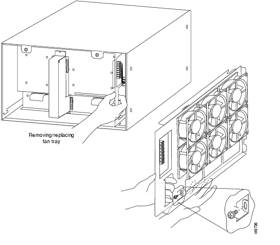
The Cisco 7505 fan tray comprises six individual fans (the fan array) and a fan control printed circuit board mounted on a metal tray (see Figure 5-2); the entire assembly is called the fan tray. The fan tray slides into the right side of the chassis (when you view the chassis from the noninterface processor end). The fans draw cooling air through the inlet vents on the left side of the chassis (when you view the chassis from the noninterface processor end) and force the air out through the exhaust vents on the right side of the chassis.
The fan control board distributes power to the fans, controls the fan speed, and monitors and reports fan failures to the system through the backplane.
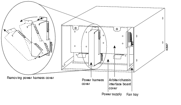
The power harness cover (see Figure 5-4) shields the wiring harness that delivers DC power from the power supply to the backplane. The power harness, which is part of all power supplies, carries DC voltages from the power supply to the backplane. The backplane distributes the operating voltages to all of the internal chassis components.
For the AC-input power supply, an external modular power cable delivers AC source power to the external AC receptacle on the interface processor end of the power supply.
For the DC-input power supply, a three-lead, 10-AWG power cable that you provide delivers DC source power to the terminal block on the power supply.
The power supply rests on the floor of the chassis, under the card cage and backplane. The noninterface processor end of the power supply has handles for pulling it out of the chassis. Before inserting a power supply, remove the cable retention clip (or secure it with tape); otherwise, it will catch on the chassis floor and prevent the chassis from sliding into the power supply bay.
The backplane cover shields the noninterface processor side of the backplane as well as the arbiter and chassis interface.
Maintenance Procedures for the Cisco 7505
The specific maintenance procedures for your Cisco 7505 router are described in the following sections:
•
•
•
•
•
•
Warning
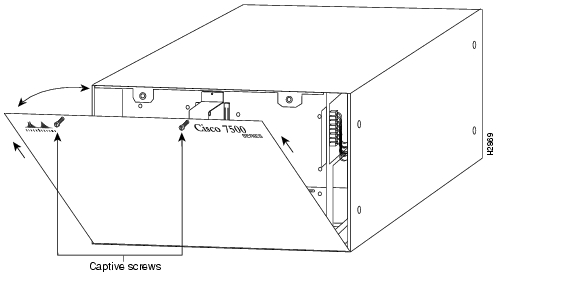
Removing and Replacing the Cisco 7505 Cover Panel
The two captive slotted screws are the only fasteners on the cover panel. Five shallow tabs at the bottom edge of the panel fit into slots at the base of the chassis opening. The tabs act as a pivot point for pulling the top of the panel away from the chassis opening, and as guides to align the panel when replacing it. If the chassis cover does not seal the end of the chassis, the flow of cooling air inside the chassis can be misrouted, which can result in an overtemperature condition.
Warning
Use the following procedure to remove the chassis cover panel:
Figure 5-1 Removing and Replacing the Cisco 7505 Cover Panel
Step 1
Step 2
Note
Use the following procedure to replace the chassis cover panel:
Step 1
Step 2
Step 3
Step 4
This completes the chassis cover panel removal and replacement procedure.
Removing and Replacing the Cisco 7505 Fan Tray
The fans on the fan tray provide cooling air to the internal system components. If the system detects that a fan has failed, it will display a 2-minute warning and then shut down the system until all of the fans are operational.
Note
Figure 5-2 Replacing the Cisco 7505 Fan Tray
When you view the chassis from the noninterface processor end, the fan tray is on the far right. See Figure 5-2.
A cutout in the front of the tray provides a handle for pulling the tray out of the chassis. An M4 Phillips screw anchors a tab on the bottom edge of the tray to the interior chassis frame, just below the right power supply ear.
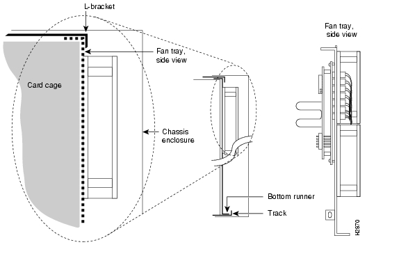
When the fan tray is fully inserted in the chassis, an edge connector on the fan control board slides into the backplane electrical connector. The bottom of the tray is a metal runner that guides the tray along a metal track on the chassis floor. (See Figure 5-3.) Also, a bracket on the chassis ceiling helps guide the tray into the chassis.
Figure 5-3 Fan Tray Tracks and Guides in the Cisco 7505
Warning
Use the following procedure to remove the fan tray:
Step 1
Step 2
Step 3
Step 4
Step 5
Step 6
Step 7
Note
Use the following procedure to replace the fan tray:
Step 1
Note
Step 2
Step 3
Step 4
Step 5
This completes the fan tray replacement procedure.
Removing and Replacing the Cisco 7505 Power Harness Cover
You must remove the power harness cover to access the power supply. A single M3 Phillips screw secures the power harness cover to the backplane cover.
Warning
Use the following procedure to remove the power harness cover:
Step 1
Step 2
Figure 5-4 Removing the Cisco 7505 Power Harness Cover
Step 3
Step 4
Step 5
Note
Use the following procedure to replace the power harness cover:
Step 1
Step 2
Step 3
Step 4
Step 5
This completes the power harness cover removal and replacement procedures.
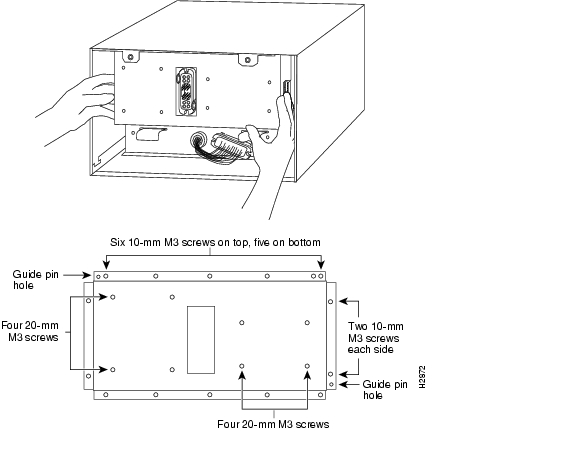
Removing and Replacing the Cisco 7505 Backplane Cover
The backplane cover provides EMI and ground protection for the backplane, the arbiter, and the chassis interface (CI). To access the CI, you must remove the backplane cover using number 1 and number 2 Phillips screwdrivers. Following is the procedure for removing and replacing the backplane cover. This procedure assumes that you have already removed the chassis cover panel, the fan tray, the power harness cover, and the power harness. If not, see the appropriate sections in this publication to remove these items.
Use the following procedure to remove the backplane cover:
Step 1
Step 2
Step 3
Caution
Step 4
Figure 5-5 Removing and Replacing the Cisco 7505 Backplane Cover
Note
Use the following procedure to replace the backplane cover:
Step 1
Step 2
Step 3
Step 4
Step 5
Step 6
Step 7
Step 8
This completes the Cisco 7505 backplane cover removal and replacement procedure.
Removing and Replacing the Chassis Interface in the Cisco 7505
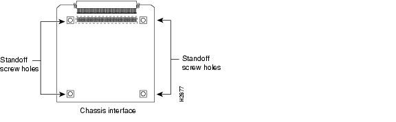
The chassis interface (CI) (shown in Figure 5-6) is a printed circuit board mounted to the noninterface processor side of the backplane, behind the backplane cover. On the back (backplane side) of the chassis are four standoffs and a connector that plugs directly into the backplane. (A spare chassis interface ships as Product Number MAS-7500CI=.)
Figure 5-6 7500 Series Chassis Interface
When the backplane cover is in place, four standoff screws extend through the backplane cover, through each corner of the CI and into the standoffs to keep both the CI and backplane cover in place.
This procedure assumes that you have already removed the chassis cover panel, the fan tray, the power harness cover, the power harness, and the backplane cover. If not, see the appropriate procedures in this section to remove these items. Replace the CI only if it fails.
Use the following procedure to remove the CI:
Step 1
Step 2
Step 3
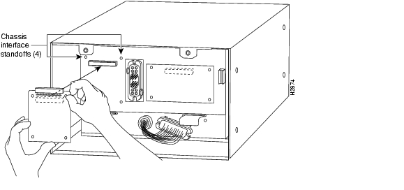
Note
Figure 5-7 Removing and Replacing the CI (Cisco 7505)
Step 4
Use the following procedure to replace the CI:
Step 1
Step 2
Note
Step 3
Step 4
Step 5
Step 6
Step 7
This completes the CI replacement procedure for the Cisco 7505.
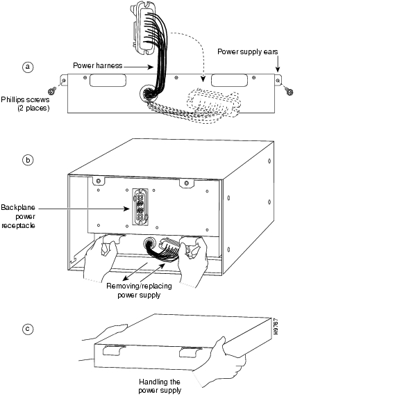
Removing and Replacing the Cisco 7505 Power Supply
The power supply rests on the floor of the chassis under the card cage and backplane. To remove the power supply, you must remove the chassis access cover at the noninterface processor end of the router, remove the power harness cover, and disconnect the harness from the backplane receptacle. Always pull the harness out by the connector, not by the wires. Before removing the power harness cover, ensure that the system power is turned off; otherwise, the backplane voltages become a hazard.
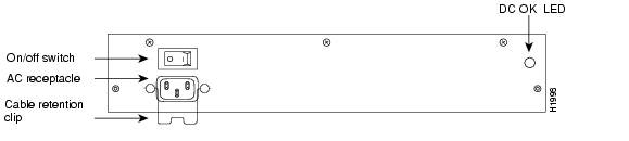
On the AC receptacle, located on the interface processor end of the AC-input power supply, a cable-retention clip snaps up and around the modular power cable connector to prevent the cable from accidentally being pulled out or from falling out. (See Figure 5-8.) When you insert the power supply, this clip can get snagged on the chassis floor. Before inserting the supply, remove the clip or tape it up out of the way.
On the DC-input power supply, a nylon cable tie provides the cable strain relief. Replace this strain relief with a new nylon cable tie after you install the new DC-input power supply. The interface processor end of the DC-input power supply has a terminal block rather than the AC receptacle. (See Figure 5-8.)
Warning
Figure 5-8 Cisco 7505 AC-Input Power Supply—Interface Processor End
The following procedure assumes you already removed the chassis cover panel, the fan tray, the power harness cover, and the power harness. If not, see the appropriate sections in this chapter. You need a number 2 Phillips screwdriver and a pair of wire cutters.
Use the following procedure to remove the power supply:
Step 1
Warning
Step 2
Step 3
Step 4
Figure 5-9 Removing and Replacing the Cisco 7505 Power Supply
Step 5
Step 6
Step 7
This completes the power supply removal procedure.
Use the following procedure to replace the power supply:
Step 1
Warning
Step 2
Step 3
Step 4
Step 5
Step 6
Step 7
Step 8
Step 9
This completes the power supply replacement procedure.
![]()
![]()
![]()
![]()
![]()
![]()
![]()
![]()
Posted: Thu Mar 24 11:31:38 PST 2005
All contents are Copyright © 1992--2005 Cisco Systems, Inc. All rights reserved.
Important Notices and Privacy Statement.