|
|

Table Of Contents
Maintaining Your Cisco 7507 and Cisco 7507-MX Router
Tools Required for Maintenance Procedures
Overview of Maintenance Procedures for the Cisco 7507 and Cisco 7507-MX
Maintenance Procedures for the Cisco 7507 and
Cisco 7507-MXRemoving Cisco 7507 and Cisco 7507-MX Power Supplies
Removing and Replacing the Cisco 7507 and Cisco 7507-MX Front Chassis Panels
Cleaning and Replacing the Cisco 7507 and Cisco 7507-MX Air Filter
Replacing Cisco 7507 and Cisco 7507-MX Internal Components
Maintaining Your Cisco 7507 and Cisco 7507-MX Router
Your Cisco 7507 or Cisco 7507-MX router is configured to your order and is ready for installation and startup when it leaves the factory. After you install and configure your router, you might have to perform specific maintenance procedures and operations to ensure that the router is operating properly, to upgrade specific system components, or to replace components with spare parts or field-replaceable units (FRUs). This chapter describes procedures and maintenance operations required to maintain your Cisco 7507 or Cisco 7507-MX router; it includes procedures for installing, adding, and replacing internal router components and replaceable spare parts.
Note
Detailed, up-to-date instructions (called configuration notes) are available on Cisco.com.
The replaceable system components fall into two categories: those that support online insertion and removal (OIR) and those that do not (requiring you to turn off the system power before replacement). For example, you can remove interface processors and replace them while the system is operating; however, you must shut down the system power before removing the RSP and the single power supply in a Cisco 7507 or Cisco 7507-MX with one power supply installed, or before accessing the chassis interior for any other reason.
This chapter provides specific component replacement instructions for upgrading, removing, or replacing the following components:
•
•
•
•
•
•
Caution
Note
Tools Required for Maintenance Procedures
You need the following tools to replace any one of the Cisco 7507 or Cisco 7507-MX internal spares:
•
•
•
•
•
Overview of Maintenance Procedures for the Cisco 7507 and Cisco 7507-MX
To replace internal spares, you must remove the chassis cover panel and expose the chassis interior.
Warning
Maintenance Procedures for the Cisco 7507 and
Cisco 7507-MXThe specific maintenance procedures for your Cisco 7507 or Cisco 7507-MX router are described in the following sections:
•
To install power supplies in the Cisco 7507 or Cisco 7507-MX, see the "Installing Cisco 7507 and Cisco 7507-MX Power Supplies" section.
•
•
•
Warning
Removing Cisco 7507 and Cisco 7507-MX Power Supplies
This section describes the procedure for removing power supplies from the Cisco 7507 and Cisco 7507-MX.
Note
Redundant power supplies support online insertion and removal (OIR); if you remove one power supply, the second supply immediately ramps up to supply full power to the system to maintain uninterrupted operation.
If you have only one power supply in your Cisco 7507 or Cisco 7507-MX, you must turn off power before removing and replacing it. Always install a filler plate over an empty power supply bay to protect the connectors from contamination.
Warning
Warning
Use the following procedure to remove a power supply:
Step 1
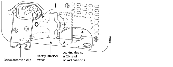
Step 2
Figure 6-1 Power Supply Interlock (Cisco 7507 and Cisco 7507-MX AC-Input Power Supply Shown)
Step 3
Step 4
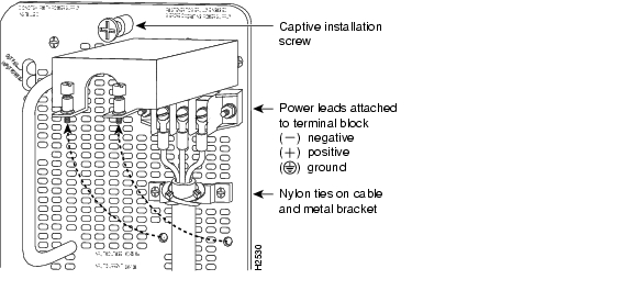
For the DC-input power supply: Loosen the captive installation screws on the terminal block cover, lift the cover, use the wire cutters to cut the nylon strain-relief ties, and then remove the three power leads (remove the ground lead last) from the terminal block.
Warning
Figure 6-2 Removing Nylon Cable Ties and Power Leads from a Cisco 7507 and Cisco 7507-MX DC-Input Power Supply
Step 5
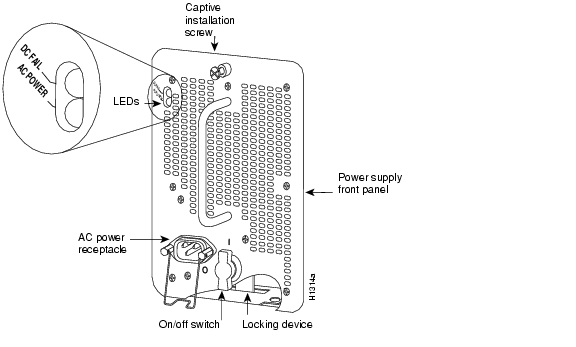
Figure 6-3 Power Supply Captive Installation Screw (Cisco 7507 and Cisco 7507-MX AC-Input Power Supply Shown)
Step 6
Warning
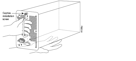
Figure 6-4 Handling a Power Supply (Cisco 7507 and Cisco 7507-MX AC-Input Power Supply Shown)
Step 7
Step 8
Note
If you plan to replace a DC-input power supply, install it using the procedure in the "Installing Cisco 7507 and Cisco 7507-MX Power Supplies" section. Rewire it using the procedure in the "Connecting Power to the Cisco 7505 DC-Input Power Supply" section.This completes the power supply removal procedure.
Removing and Replacing the Cisco 7507 and Cisco 7507-MX Front Chassis Panels
This section provides the procedures for removing and replacing the chassis top front panel and bottom front panel so you can access internal chassis components or replace panels that have been damaged.
The bottom front chassis panel is vented and works with the chassis blower to draw cooling air into the chassis. If the bottom panel is not installed correctly, or if it is cracked or broken, the flow of cooling air can be redirected and might cause overheating inside the chassis. Replace panels if they are cracked or broken, or if damage prevents them from fitting on the chassis properly.
Always shut down the system before removing the chassis top front panel. With the top front panel removed, 100A of current is exposed on the front of the backplane and around the power supply wiring harnesses.
Warning
Note
Use the following procedure to remove the front panels:
Step 1
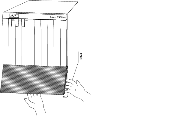
Figure 6-5 Removing the Cisco 7507 and Cisco 7507-MX Bottom Front Panel
.
Step 2
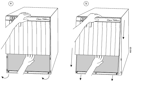
Figure 6-6 Removing the Cisco 7507 and Cisco 7507-MX Top Front Panel
Step 3
Step 4
Step 5
Step 6
Note
Use the following procedure to replace the front chassis panels:
Step 1
Step 2
Step 3
Step 4
Step 5
Step 6
Step 7
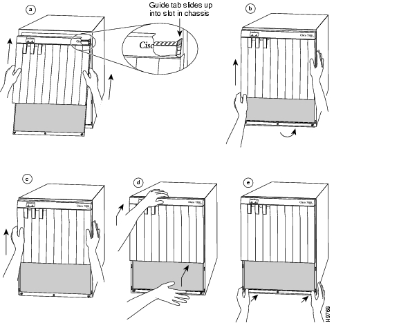
Figure 6-7 Replacing the Cisco 7507 and Cisco 7507-MX Front Panels
Step 8
Step 9
This completes the chassis front panel removal and replacement procedures.
Cleaning and Replacing the Cisco 7507 and Cisco 7507-MX Air Filter
In the Cisco 7507 and Cisco 7507-MX, the air filter removes dust from the air drawn in by the blower. The edges of the air filter fit into the lower frame of the top front chassis panel. You should remove and vacuum the air filter at least once every 2 weeks, or more often in unusually dusty environments. If vacuuming is not possible, you can remove the filter and wash it, but ensure that it is completely dry before replacing it in the chassis. Have spares on hand in case the filter tears or becomes worn. A dirty filter can prohibit the flow of cooling air into the chassis and might cause an overtemperature condition. If you can remove, clean, and replace the filter within 5 minutes, you do not need to shut down the system power.
Caution
You need to remove the bottom front chassis panel to access and remove the filter, and then move the filter away from the chassis for vacuuming. Vacuuming can dislodge substantial amounts of dust, and cleaning the filter near the opened chassis can allow loose particles to enter the chassis through the unfiltered blower. Therefore, we recommend that you briefly remove the panel to clean it, and then immediately replace it in the chassis.
Use the following procedure to check the air filter and clean or replace it if necessary:
Step 1
Step 2
Step 3
Step 4
Step 5
Step 6
Step 7
Step 8
Caution
Replacing Cisco 7507 and Cisco 7507-MX Internal Components
The replaceable internal components in the Cisco 7507 and Cisco 7507-MX are accessible by removing the top and bottom front chassis panels. Always turn off the system power before removing the chassis top front panel. With the top front panel removed, 100A of current is exposed on the front of the backplane and around the power supply wiring harnesses. Replace the internal components only if you are advised to do so by a Cisco service representative.
This section contains replacement procedures for the following equipment:
•
•
•
Note
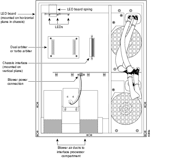
Figure 6-8 Cisco 7507 and Cisco 7507-MX Internal Chassis Components
Warning
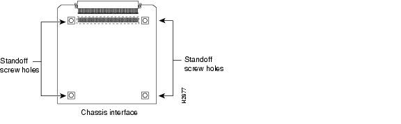
Removing and Replacing the Chassis Interface in the Cisco 7507 and Cisco 7507-MX
The chassis interface (CI) (shown in Figure 6-9) provides environmental monitoring and logic functions for the Cisco 7507 and Cisco 7507-MX. The CI is a printed circuit board mounted to the noninterface processor side (rear) of the backplane. The CI plugs directly into the backplane through the edge connector on the CI and a connector on the rear of the backplane. The chassis interface ships as a spare part as Product Number MAS-7500CI=. Replace the CI only if it fails.
Figure 6-9 7500 Series Chassis Interface
Use the following procedure to remove the CI:
Step 1
Step 2
Step 3
Step 4
Step 5
Note
Step 6
This completes the CI removal procedure.
Use the following procedure to replace the CI:
Step 1
Step 2
Step 3
Step 4
This completes the CI replacement procedure for the Cisco 7507 and Cisco 7507-MX.
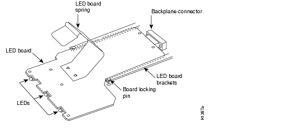
Removing and Replacing the Cisco 7507 and Cisco 7507-MX LED Board
The LED board contains the three status LEDs that provide system and power supply status on the front panel. Replace the LED board only if it fails or if one of the LEDs fails.
The LED board is mounted on a horizontal plane near the top of the chassis interior. See Figure 6-8. The board slides into two brackets mounted to the front of the backplane and attaches to a connector on the backplane. Two pins in the brackets and a metal spring keep the board in place. Figure 6-10
Use the following procedure to remove the existing LED board:
Step 1
Step 2
Step 3
Step 4
Figure 6-10 LED Board (Cisco 7507 and Cisco 7507-MX)
Caution
Step 5
Step 6
Step 7
This completes the LED board removal procedure.
Use the following procedure to install a new LED board:
Step 1
Step 2
Step 3
Step 4
Step 5
Step 6
Step 7
This completes the LED board installation procedure.
Use the following procedure to verify that the new LED board is installed correctly:
Step 1
Step 2
a.
b.
Step 3
a.
b.
Step 4
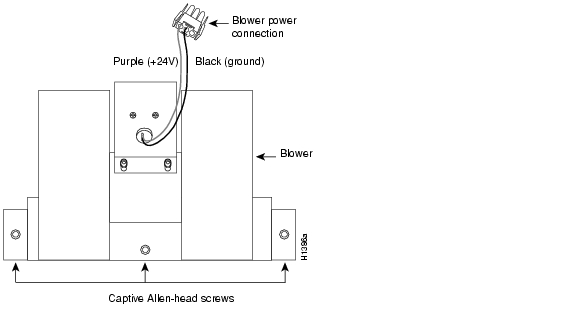
Removing and Replacing the Cisco 7507 and Cisco 7507-MX Blower Assembly
The chassis blower draws cooling air in through the chassis bottom front panel and sends it up through the floor of the inner rear compartment to cool the RSP(s) and interface processors. The absence of cooling air can cause the interior of the chassis to heat up and might cause an overtemperature condition.
Caution
The blower is located at the bottom of the chassis interior. Two air ducts on the rear of the blower, shown shaded in Figure 6-8, fit snugly into the two cutouts in the backplane. The blower is secured to the backplane with three large captive Allen-head screws, which are shown in Figure 6-11 .
Figure 6-11 Chassis Blower (Cisco 7507 and Cisco 7507-MX)
Warning
Use the following procedure to remove the existing chassis blower:
Step 1
Step 2
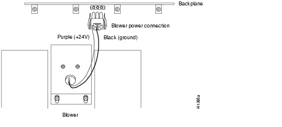
Step 3
Figure 6-12 Blower Power Connection (Cisco 7507 and Cisco 7507-MX)
Step 4
Step 5
Step 6
Step 7
Step 8
Step 9
Step 10
Note
Caution
This completes the chassis blower assembly removal procedure.
Use the following procedure to install a new chassis blower assembly:
Step 1
Warning
Step 2
Step 3
Step 4
Step 5
Step 6
The far left screw is slightly obscured by the left lip of the chassis and the left blower air duct, but is accessible by inserting a long Allen wrench into the access hole in the lower lip of the chassis. Insert the wrench straight into the hole at a 90-degree angle to the backplane. If necessary, use a flashlight to locate and guide the wrench to the screw.
If a screw is hard to turn, do not force it. Wiggle the chassis around, ensure that the screw is straight, and try tightening the screw again. If after several attempts the screw does not tighten easily, see the installation verification procedure that follows for further instructions.
Step 7
Step 8
Step 9
This completes the chassis blower assembly installation procedure.
Use the following procedure to verify that the new blower is installed correctly:
Step 1
If any do not, or if the DC fail LED on the AC-input power supply (or the out fail LED on the DC-input power supply) is on, the power supply has failed. (If required, see the troubleshooting procedures in "Troubleshooting a Cisco 7500 Series Router.")
Step 2
a.
b.
c.
d.
Step 3
If after several attempts the blower does not operate, or if you experience trouble with the installation, contact a service representative for assistance.
This completes the blower replacement procedure.
![]()
![]()
![]()
![]()
![]()
![]()
![]()
![]()
Posted: Thu Mar 24 11:28:37 PST 2005
All contents are Copyright © 1992--2005 Cisco Systems, Inc. All rights reserved.
Important Notices and Privacy Statement.