cc/td/doc/product/core/cis7505
hometocprevnextglossaryfeedbacksearchhelp
PDF

Table Of Contents

Maintaining Your Cisco 7513, Cisco 7513-MX, and Cisco 7576 Router

Tools Required for Maintenance Procedures

Maintenance Procedures for the Cisco 7513, Cisco 7513-MX, and Cisco 7576

Removing Cisco 7513, Cisco 7513-MX, and Cisco 7576 Power Supplies

Removing and Replacing the Cisco 7513, Cisco 7513-MX, and Cisco 7576 Card Cage Assembly

Removing and Replacing the Cisco 7513, Cisco 7513-MX, and Cisco 7576 Blower Module

Removing and Replacing the Cisco 7513, Cisco 7513-MX, and Cisco 7576 Chassis Cover Panels

Removing and Replacing the Cisco 7513, Cisco 7513-MX, and Cisco 7576 Backplane Maintenance Cover

Removing and Replacing the Chassis Interface in the Cisco 7513, Cisco 7513-MX, and Cisco 7576


Maintaining Your Cisco 7513, Cisco 7513-MX, and Cisco 7576 Router


Your Cisco 7513, Cisco 7513-MX, or Cisco 7576 router is configured to your order and is ready for installation and startup when it leaves the factory. After you install and configure your router, you might have to perform specific maintenance procedures and operations to ensure that the router is operating properly, to upgrade specific system components, or to replace components with spare parts or field-replaceable units (FRUs). This chapter describes procedures and maintenance operations required to maintain your Cisco 7513, Cisco 7513-MX, or Cisco 7576 router.


Note Detailed, up-to-date instructions (called configuration notes) are available on Cisco.com.


The Cisco 7513, Cisco 7513-MX, and Cisco 7576 allow you to remove and replace interface processors and RSPs while the system is powered on; however, you must shut down the system power before accessing the chassis interior for any other reason.


Note If you intend to remove and replace an interface processor or RSP while the system is powered on, do so only when no operations are taking place that involve the RSP NVRAM or Flash memory. This includes operations involving system configuration changes and downloading microcode images.


This chapter provides specific component replacement instructions for upgrading, removing, or replacing the following components:

Chassis cover panels

Blower module assembly

Card cage assembly

Chassis interface (CI) board

Power supply removal (power supply installation is discussed in the "Installing Cisco 7513, Cisco 7513-MX, and Cisco 7576 Power Supplies" section).


Caution To help prevent problems, before performing any procedures in this chapter, review the "Safety Recommendations" section.


Note Interface processor-specific configuration information is included in the companion Interface Processor Installation and Configuration Guide, which shipped with your Cisco 7513, Cisco 7513-MX, or Cisco 7576 router, as well as in the individual configuration notes that shipped with your spare interface processors.


Tools Required for Maintenance Procedures

You need the following tools to replace any one of the Cisco 7513, Cisco 7513-MX, and Cisco 7576 internal spares:

3/16-inch flat-blade screwdriver to loosen the captive screws on the processor modules, power supplies, card cage assembly, and the DC-input terminal connections on DC-input power supplies

Number 1 Phillips screwdriver to loosen captive screws on processor modules that have this type of screw

Number 2 Phillips screwdriver to remove teh backplane cover screws

Maintenance Procedures for the Cisco 7513, Cisco 7513-MX, and Cisco 7576

To replace internal spares, all of which are inside the noninterface processor end of the router, you must remove the chassis cover panel and expose the chassis interior. The Cisco 7513, Cisco 7513-MX, and Cisco 7576 are housed in the same chassis and use the same power supplies. If a procedure is specific to one model or the other, it is noted within that procedure.


Warning If the power is not shut down before removing chassis cover panels, high current can become a hazard. When the power harness cover is removed, the high current present in the wiring and on the backplane also becomes a hazard. Removing metal cover panels when the system is operating also compromises the EMI integrity of the system. Therefore, always turn off the system power before removing metal cover panels, and remove cover panels only when it is necessary to replace internal components.


The specific maintenance procedures for your Cisco 7513, Cisco 7513-MX, or Cisco 7576 router are described in the following sections:

Removing Cisco 7513, Cisco 7513-MX, and Cisco 7576 Power Supplies


Note To install power supplies in the Cisco 7513, Cisco 7513-MX, and Cisco 7576, see the "Installing Cisco 7513, Cisco 7513-MX, and Cisco 7576 Power Supplies" section.


Removing and Replacing the Cisco 7513, Cisco 7513-MX, and Cisco 7576 Card Cage Assembly

Removing and Replacing the Cisco 7513, Cisco 7513-MX, and Cisco 7576 Blower Module

Removing and Replacing the Cisco 7513, Cisco 7513-MX, and Cisco 7576 Chassis Cover Panels

Removing and Replacing the Cisco 7513, Cisco 7513-MX, and Cisco 7576 Backplane Maintenance Cover

Removing and Replacing the Chassis Interface in the Cisco 7513, Cisco 7513-MX, and Cisco 7576


Warning Before working on a system that has an on/off switch, turn OFF the power and unplug the power cord.


Removing Cisco 7513, Cisco 7513-MX, and Cisco 7576 Power Supplies

This section describes the procedure for removing a power supply from the Cisco 7513, Cisco 7513-MX, and Cisco 7576.


Note The procedure for installing power supplies in the Cisco 7513, Cisco 7513-MX, and Cisco 7576 is described in the "Installing Cisco 7513, Cisco 7513-MX, and Cisco 7576 Power Supplies" section.


Redundant power supplies support online insertion and removal (OIR); if you remove one power supply, the second supply immediately ramps up to supply full power to the system to maintain uninterrupted operation.

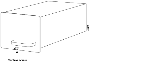
If you have only one power supply in your Cisco 7513, Cisco 7513-MX, or Cisco 7576, you must turn off power before removing and replacing it. Always install a filler plate over an empty power supply bay to protect the connectors from contamination.


Warning When stranded wiring is required, use approved wiring terminations, such as closed-loop or spade-type with upturned lugs. These terminations should be the appropriate size for the wires and should clamp both the insulation and the conductor.


Warning Before performing any of the following procedures, ensure that power is removed from the DC circuit. To ensure that all power is OFF, locate the circuit breaker on the panel board that services the DC circuit, switch the circuit breaker to the OFF position, and tape the switch handle of the circuit breaker in the OFF position.


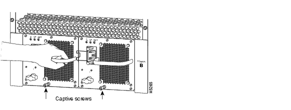
Use the following procedure to remove a power supply:


Step 1 If you have two power supplies installed and one power supply has failed, turn off (O) the system power switch on the power supply you will remove.

Step 2 AC-input power supply: Using a screwdriver, loosen the cable-retention clip on the power cable and unplug the power cable from the AC receptacle.

DC-input power supply: Disconnect the power cable leads from a DC-input power supply. (See the "Connecting Power to Cisco 7513, Cisco 7513-MX, and Cisco 7576 DC-Input Power Supplies" section.) Then, with the power cable leads disconnected, proceed to Step 3.

Step 3 Use a flat-blade screwdriver to loosen the captive screw that secures the power supply to the chassis frame.

Figure 7-1 Removing a Power Supply (Cisco 7513, Cisco 7513-MX, and Cisco 7576 AC-Input Power Supplies Shown)
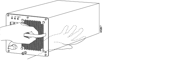
Step 4 Grasp the power supply handle and pull the power supply about halfway out of the bay (approximately 8 inches [20 cm]); then with your other hand under the power supply, pull it completely out of the bay.

Figure 7-2 Supporting the Power Supply (Cisco 7513, Cisco 7513-MX, and Cisco 7576 AC-Input Power Supply Shown)


Caution To maintain agency compliance requirements and meet EMI emissions standards in Cisco 7513, Cisco 7513-MX, and Cisco 7576 chassis with a single power supply, a power supply blank must remain in the power supply bay adjacent to the power supply. Do not remove this blank from the chassis unless you do so to install a redundant power supply.


Note To prevent system problems, do not mix AC-input and DC-input power supplies.


Warning High current levels on the power supply connections at the rear of the power supply bay are exposed with the power supply or blank removed. Do not insert anything conductive into the open power supply bay while power is ON.


Figure 7-3 Power Supply Blank (Cisco 7513, Cisco 7513-MX, and Cisco 7576)


This completes the power supply removal procedure.

For the procedure for installing power supplies in the Cisco 7513, Cisco 7513-MX, and Cisco 7576, see the "Installing Cisco 7513, Cisco 7513-MX, and Cisco 7576 Power Supplies" section.

Removing and Replacing the Cisco 7513, Cisco 7513-MX, and Cisco 7576 Card Cage Assembly

The card cage comprises one assembly that includes the card cage and backplane. The assembly slides into and out of the chassis and attaches to the chassis frame with four slotted captive screws.

The following procedure requires that you first remove the processor modules from the card cage; see the procedure in Figure 3-14.

Removing the Card Cage Assembly

Use the following procedure to remove the card cage assembly. This procedure cannot be performed with power supplies or power supply blanks installed.


Step 1 Remove all processor modules from the chassis card cage.

Make a note of the processor module slots as you remove the processor modules. Do not stack the processor modules on top of one another.

It is possible to remove the card cage from the chassis with the processor modules installed; however, it is not recommended. Thirteen processor modules add 32.5 lb (14.7 kg) to the system.
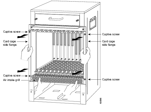
Step 2 Remove the power supplies. (See the "Removing Cisco 7513, Cisco 7513-MX, and Cisco 7576 Power Supplies" section.)

Step 3 With the processor modules and power supplies removed, loosen the four large captive screws located on the card cage flanges, to the left and right of the card cage opening, as shown in Figure 7-4.

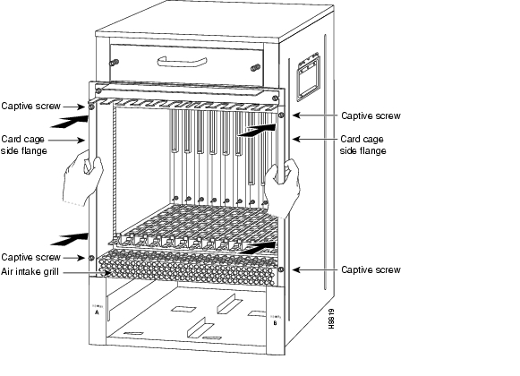
Figure 7-4 Removing the Cisco 7513, Cisco 7513-MX, and Cisco 7576 Card Cage Assembly


Caution Unless the chassis is mounted in a rack, or otherwise anchored, the chassis might move toward you when you pull the card cage and backplane assembly in the following step. To prevent injury, have a second person hold the chassis in place while you pull the card cage and backplane assembly from the chassis.

Step 4 With the captive screws loosened, carefully grasp the intake grill with both hands and pull the card cage assembly straight out of the chassis until there is enough clearance at the card cage side flanges to pull the entire assembly clear of the chassis sides, as shown in Figure 7-4. The assembly is heavier at the backplane and might be awkward to handle.

Step 5 When the card cage and backplane assembly is completely free of the chassis, carefully place it on an antistatic mat or foam.


Caution The electronic components on the rear of the backplane are completely exposed when the card cage and backplane assembly is removed from the chassis. To prevent damaging these components, place the card cage and backplane assembly on an antistatic mat or foam, and place the assembly in the same orientation as when it is mounted in the chassis.


Note If you plan to replace your existing card cage assembly with a new one, you must first perform the procedure in the "Exchanging the EEPROM Devices" section before you install your new card cage assembly. However, if you simply plan to remove your card cage assembly and then reinstall it, you do not need this procedure; instead, proceed to the "Installing the Card Cage Assembly" section.


Exchanging the EEPROM Devices

The following procedure requires you to first exchange the blank EEPROM devices on your new card cage for the old EEPROM devices from your old card cage, and then place the blank EEPROM devices on your old card cage for return to Cisco Systems.


Note You do not need to perform this procedure if you do not plan to install a new card cage assembly; however, if you do plan to install a new card cage assembly, you must exchange the new electrically erasable programmable read-only memory (EEPROM) devices on the rear of the new card cage for the old EEPROM devices on the rear of your old card cage.


The EEPROM devices on your old card cage have MAC addresses programmed into them, which are necessary for your system to function properly, and these old EEPROM devices are therefore required for your system to operate properly with a new card cage assembly.


Note Do not perform these steps if you are upgrading a Cisco 7513 to a Cisco 7576. These instructions apply only to the replacement of an equivalent model card cage.


Caution To prevent system problems after installation, note that the new EEPROM devices that shipped on your new card cage are blank and must be replaced if you plan to replace your card cage with a new one.

For this procedure, you will need a small piece of masking or cellophane tape to mark the new EEPROM devices as blank. (The old card cage is assumed to have already been removed from your Cisco 7513, Cisco 7513-MX, or Cisco 7576 using the procedure in the "Removing the Card Cage Assembly" section.)

Use the following procedure to exchange the EEPROM devices:


Step 1 Attach an ESD preventive wrist strap between you and an unpainted surface of the Cisco 7513, Cisco 7513-MX, or Cisco 7576 chassis.

Step 2 Locate the blank EEPROM devices, located on the rear of the new card cage near the chassis interface board(s). (See Figure 7-5 for the Cisco 7513 and Cisco 7513-MX, and Figure 7-6 for the Cisco 7576.)

Step 3 Remove the blank EEPROM devices from the new card cage, place a piece of tape on them to mark them as blank EEPROM devices, and set them aside.

Step 4 Locate the old EEPROM devices, located on the rear of your old card cage. (See Figure 7-5 for the Cisco 7513 and Cisco 7513-MX, and Figure 7-6 for the Cisco 7576.)

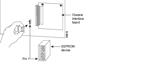
Figure 7-5 Location of the EEPROM Device on the Rear of the Card Cage (Cisco 7513 and Cisco 7513-MX)

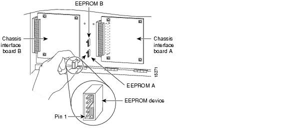
Figure 7-6 Location of the EEPROM Devices on the Rear of the Card Cage
(Cisco 7576)

Step 5 Remove the old EEPROM devices from the old card cage. Note where pin 1 is and use it as a reference insertion point. Immediately install the old EEPROM devices on the EEPROM sockets on your new card cage. (See Figure 7-5 for the Cisco 7513 and Cisco 7513-MX, and Figure 7-6 for the Cisco 7576.)

Step 6 Install the blank EEPROM devices)(that you removed from your new card cage and marked with tape) on the EEPROM sockets on your old card cage; remove the small piece of tape from the blank EEPROM devices. Return the old card cage to Cisco Systems.

Step 7 Repeat Step 5 and Step 6 for the second EEPROM in the Cisco 7576.


This completes the procedure for exchanging the EEPROM devices, which is required only if you exchange your existing card cage assembly for a new one.

Installing the Card Cage Assembly

Use the following procedure to install the card cage assembly.


Caution The electronic components on the rear of the backplane are completely exposed when the card cage and backplane assembly is removed from the chassis. To prevent damaging these components, carefully slide the assembly into the chassis opening.

Figure 7-7 Installing the Card Cage Assembly


Step 1 Carefully lift the card cage assembly, place it into the chassis opening, and slide the assembly into the chassis opening until the left and right flanges on the card cage are flush with the chassis flanges.

Step 2 Squeeze the card cage and chassis flanges together, and tighten each captive screw. Do not overtighten the captive screws.

Step 3 Carefully replace the processor modules in the card cage. (See the procedure shown in Figure 3-14.)

Step 4 Reinstall the power supplies in the Cisco 7513, Cisco 7513-MX, or Cisco 7576. (See the "Installing Cisco 7513, Cisco 7513-MX, and Cisco 7576 Power Supplies" section.)


This completes the procedure for installing the card cage assembly in the Cisco 7513,
Cisco 7513-MX, and Cisco 7576.

Removing and Replacing the Cisco 7513, Cisco 7513-MX, and Cisco 7576 Blower Module

In the Cisco 7513, Cisco 7513-MX, and Cisco 7576, the blower provides cooling air to the internal system components. When you view the chassis from the noninterface processor end, the blower module is located above the card cage. (See Figure 1-11.) Two slotted captive screws hold the blower module in place. The front panel LEDs are located on a printed circuit board inside the blower module. If one of these LEDs fails, the blower module must be replaced. The LED board inside the blower module assembly is not separately replaceable.


Warning Although the system should not be operating when you remove the blower module, it is not necessary to turn OFF system power before removing the blower module. However, with the system power ON and the blower module removed, high current is exposed on the blower module power connector at the backplane; do not insert conductive items into the empty blower module opening. After an operating blower module is removed, the blower impeller blades will continue to spin for approximately two minutes; do not insert anything into the module's vent holes while the impeller is spinning.


Caution With chassis power on and the blower module removed, no cooling air is circulating through the system. Replace the blower module before the system overheats. The system will shut down approximately 2 minutes after reaching the shutdown temperature threshold.

Use the following procedure to remove and replace the blower module:


Step 1 Loosen the captive screws that fasten each end of the blower module using a flat-blade screwdriver. (See Figure 7-8.)

Step 2 Grasp the handle on the front of the module and slowly pull it straight out of the chassis. (See Figure 7-8.)

Step 3 Replace the blower module. Using both hands to handle the module, and with the intake vents on the blower module facing down and the "Insert This Side Up" label facing up, insert the module into the chassis opening. Keep the module as straight as possible as you guide it into the chassis.

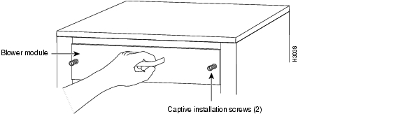
Figure 7-8 Removing the Cisco 7513, Cisco 7513-MX, and Cisco 7576 Blower Module

Step 4 When the blower is all the way into the chassis opening, tighten the captive installation screws on the front of the blower module.


This completes the blower module removal and replacement procedure.

Removing and Replacing the Cisco 7513, Cisco 7513-MX, and Cisco 7576 Chassis Cover Panels

Each cover panel on the Cisco 7513, Cisco 7513-MX, and Cisco 7576 has four fasteners that secure the panels to the front of the chassis. The following procedures describe how to remove and replace the front cover panels.


Step 1 Use a 3/16-inch flat-blade screwdriver to gently loosen the top of each cover panel.

Step 2 Pull the top of the upper panel out about 2 inches (5.08 cm); grasp the sides and carefully pull it outward, away from the chassis. Repeat this for the bottom panel.


Note See the appropriate sections depending on the replacement procedures you need to perform. Then, to replace the chassis cover panels, proceed to Step 3.


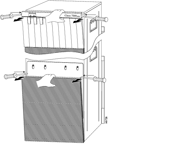
Figure 7-9 Removing the Cisco 7513, Cisco 7513-MX, and Cisco 7576 Cover Panels

Step 3 Starting with the bottom cover panel, replace the cover panels by aligning the pins on the bottom panel with the holes in the chassis and pushing the panel against the chassis. Repeat this for the top panel.


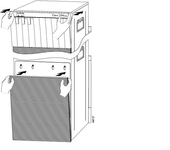
Figure 7-10 Replacing the Cisco 7513, Cisco 7513-MX, and Cisco 7576 Cover Panels

Removing and Replacing the Cisco 7513, Cisco 7513-MX, and Cisco 7576 Backplane Maintenance Cover

The backplane maintenance cover provides EMI and ground protection for the chassis interior. To access the chassis interior, you must remove the backplane cover. You need a number 2 Phillips screwdriver to remove the cover screws.

Following is the procedure for removing and replacing the backplane maintenance cover. This procedure assumes you have already removed the front panels. If not, see the appropriate procedures in this chapter to remove these items.


Step 1 Attach an ESD-preventive strap between you and an unpainted chassis surface.

Step 2 Loosen the ten Phillips screws that secure the cover.

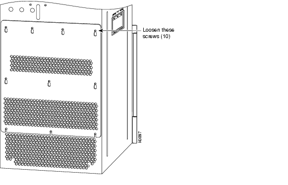
Figure 7-11 Removing the Cisco 7513, Cisco 7513-MX, and Cisco 7576 Backplane Maintenance Cover

Step 3 Carefully guide the cover up and away from the chassis.


Note See the appropriate sections depending on the replacement procedures you need to perform. Then, to replace the maintenance cover, proceed to Step 4.


Step 4 Replace the maintenance cover by carefully guiding the cover over the ten screws.

Step 5 Align the cover; then tighten all ten screws that secure it to the chassis.


This completes the backplane maintenance cover removal and replacement procedure.

Removing and Replacing the Chassis Interface in the Cisco 7513, Cisco 7513-MX, and Cisco 7576

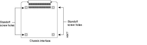
In the Cisco 7513, Cisco 7513-MX, and Cisco 7576, the chassis interface (CI) (shown in Figure 7-12) provides environmental monitoring and logic functions. The Cisco 7513 and Cisco 7513-MX has one chassis interface, and the Cisco 7576 has two chassis interfaces.

Figure 7-12 Cisco 7500 Series Chassis Interface

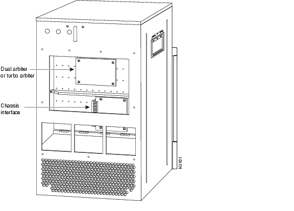
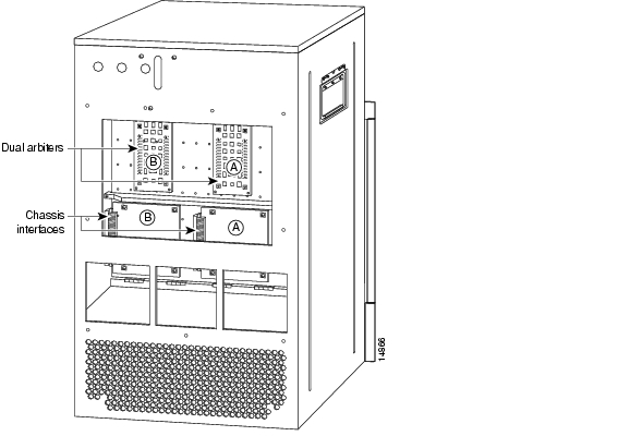
The CI is a printed circuit board mounted to the noninterface processor side of the backplane, behind the backplane maintenance cover. The Cisco 7513 and Cisco 7513-MX have one dual arbiter and one chassis interface. The Cisco 7576 has two dual arbiters and two chassis interfaces. (See Figure 7-13.) On the back of the CI (backplane side) is a connector that plugs directly into the backplane. The edge connector is for diagnostics at the factory and is not used.

Figure 7-13 Location of the CI with Maintenance Cover Removed (Cisco 7513 and Cisco 7513-MX Shown)

Figure 7-14 Location of the CIs with Maintenance Cover Removed (Cisco 7576 shown)


Note When you view the rear of the card cage, the dual arbiter and chassis interface on the right side are used with router A, and the dual arbiter and chassis interface on the left side are used with router B.


The following procedure assumes you have already removed the chassis cover panels and backplane maintenance cover. If not, see the appropriate procedures in this chapter to remove these items. Replace the CI only if it fails.

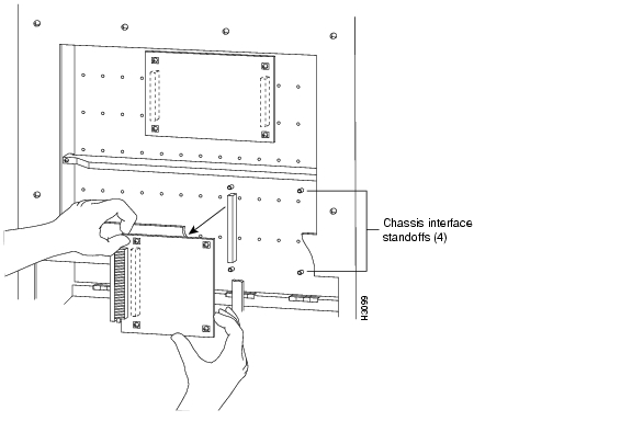
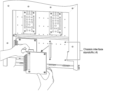
The following procedures apply to the Cisco 7513, Cisco 7513-MX, and Cisco 7576. The only difference is that the Cisco 7576 has two CIs on the backplane, as shown in Figure 7-14. If you have a CI problem with a Cisco 7576, determine which CI has failed, and replace only the failed CI.

Use the following procedure to remove the CI:


Step 1 Turn off the power switch on each power supply and disconnect the power cable from each power source and power supply.

Step 2 Attach an ESD-preventive strap between you and an unpainted chassis surface.

Step 3 The CI is held in place by a connector, which is connected to the backplane, and four screws. Use a number 1 Phillips screwdriver to remove the four screws.


Caution Access to the CI is partially blocked by a chassis panel. (See Figure 7-13 for the Cisco 7513 and Cisco 7513-MX and Figure 7-14 for the Cisco 7576.) Two of the screws are below this panel, and two are above it. To avoid damaging CI components, do not hit the CI against the chassis panel.

Step 4 Grasp the edges of the CI (as shown in Figure 7-15 for the Cisco 7513 and Cisco 7513-MX, and Figure 7-16 for the Cisco 7576) and pull it away from the backplane, up and out from behind the chassis panel. If necessary, gently rock the CI from side to side very slightly to dislodge its connector pins from the backplane connector.

Figure 7-15 Removing and Replacing the Cisco 7513 and Cisco 7513-MX CI (Cutaway View)

Figure 7-16 Removing and Replacing the Cisco 7576 CI (Cutaway View)

Step 5 Place the CI in an antistatic bag.


This completes the CI removal procedure.

Use the following procedure to replace the CI:


Step 1 Attach an ESD-preventive strap between you and an unpainted chassis surface.

Step 2 Position the CI in the orientation shown in Figure 7-15 for the Cisco 7513 and Cisco 7513-MX, and Figure 7-16 for the Cisco 7576. Position the CI over the backplane connector and align the four standoff holes in the corners of the board with the four standoffs.


Caution Access to the backplane socket is partially blocked by a chassis panel. Two of the screws are below this panel and two are above it. To avoid damaging CI components when you install the CI, do not hit the CI against the chassis panel.

Step 3 Place your fingers around the edges of the CI and carefully guide it over the chassis panel (see Figure 7-15 for the Cisco 7513 and Cisco 7513-MX, and Figure 7-16 for the Cisco 7576), and push it straight in toward the backplane until the CI connector is fully seated in the backplane socket and the standoff screw holes are aligned with the standoffs. It might be necessary to rock the connectors gently into place.

Step 4 Install the four Phillips screws that secure the CI and gently tighten them. Do not overtighten these screws.

Step 5 Replace the backplane maintenance cover. (Follow Step 4 and Step 5 in the "Removing and Replacing the Cisco 7513, Cisco 7513-MX, and Cisco 7576 Backplane Maintenance Cover" section.)

Step 6 Replace the chassis cover panels. (Follow Step 3 in the "Removing and Replacing the Cisco 7513, Cisco 7513-MX, and Cisco 7576 Chassis Cover Panels" section.)

Step 7 Reconnect the power supplies and power sources.


This completes the CI replacement procedure in the Cisco 7513, Cisco 7513-MX, and Cisco 7576.


hometocprevnextglossaryfeedbacksearchhelp

Posted: Thu Mar 24 11:34:00 PST 2005
All contents are Copyright © 1992--2005 Cisco Systems, Inc. All rights reserved.
Important Notices and Privacy Statement.