|
|

Table Of Contents
Installing a Cisco 7500 Series Router
Cisco 7500 Series General Installation Considerations
Providing a Ground Connection for the Chassis
Cisco 7505 Installation Considerations
Attaching the Cisco 7505 Cable-Management Brackets
Connecting Power to the Cisco 7505 DC-Input Power Supply
Installing the Cisco 7507 and Cisco 7507-MX
Cisco 7507 and Cisco 7507-MX Installation Considerations
Installing Cisco 7507 and Cisco 7507-MX Power Supplies
Connecting Power to Cisco 7507 or Cisco 7507-MX DC-Input Power Supplies
Installing the Cisco 7513, Cisco 7513-MX, and Cisco 7576
Cisco 7513, Cisco 7513-MX, and Cisco 7576 Installation Considerations
Attaching the Cisco 7513, Cisco 7513-MX, and Cisco 7576 Cable-Management Bracket
Installing Cisco 7513, Cisco 7513-MX, and Cisco 7576 Power Supplies
Connecting Power to Cisco 7513, Cisco 7513-MX, and Cisco 7576 DC-Input Power Supplies
Making Cable Connections to the RSP
Connecting a Console Terminal to the RSP
Connecting to the Auxiliary Port
Using the Y-Cables for Console and Auxiliary Connections
Installing a Cisco 7500 Series Router
This chapter provides guidelines and instructions you need for installing your Cisco 7500 series router, including rack-mounting and general installation considerations. This chapter also includes a rack-mounting procedure for the Cisco 7505; however, rack-mounting procedures for the Cisco 7507, Cisco 7507-MX, Cisco 7513, Cisco 7513-MX, and Cisco 7576 are far more extensive and beyond the scope of this publication.
For Cisco 7507, Cisco 7507-MX, Cisco 7513, Cisco 7513-MX, and Cisco 7576 rack-mounting procedures, refer to the following two publications, which accompany the Cisco 7507, Cisco 7507-MX, Cisco 7513, Cisco 7513-MX, and Cisco 7576 rack-mount kit (ACS-7000RMK=):
•
Cisco 7000 and Cisco 7507 Rack-Mount Kit Installation Instructions (Document Number 78-1058-xx)
•
(Document Number 78-2023-xx)Both of these publications are available on the Documentation CD-ROM and on Cisco.com.
Before you begin the installation procedures, we recommend that you also refer to the following sections in "Preparing for Installation":
•
•
•
•
•
•
Cisco 7500 Series General Installation Considerations
Before you begin the installation, the Cisco 7500 series router should already be in the area where you will install it, and your installation location should already be determined. Ensure that you have planned a clean, safe location for the chassis and that you have considered the following:
•
•
•
•
•
•
•
•
Note
Providing a Ground Connection for the Chassis
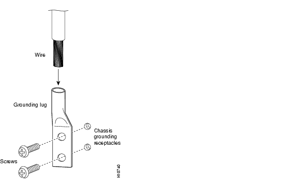
Before you connect power or turn on power to your router, we strongly recommend that you provide an adequate chassis ground (earth) connection for your router chassis. Chassis grounding receptacles are provided on each Cisco 7500 series router chassis.
To ensure the chassis grounding connection that you provide is adequate, you will require the following parts and tools:
•
•
•
•
•
•
Use the following procedure to attach the grounding lug to the chassis grounding receptacles on your router chassis:
Step 1
Figure 3-1 Attaching a Grounding Lug to the Chassis Grounding Receptacles
Step 2
Step 3
Step 4
Step 5
Step 6
Step 7
This completes the procedure for providing a chassis ground connection.
After you ensure that your site environment meets all guidelines, choose from the following sections depending on the Cisco 7500 series model you plan to install:
•
•
Then see the "What Do I Do Now?" section.
Installing the Cisco 7505
This section provides procedures for installing, rack-mounting, and attaching the cable-management brackets on a Cisco 7505, and for connecting a power cable to the power supply.
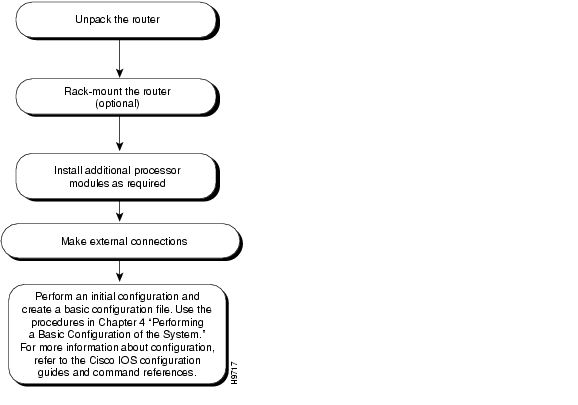
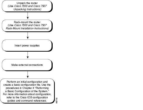
Figure 3-2 shows a flowchart that illustrates the recommended order of procedures to install the Cisco 7505 router and attach external cables to it. It also indicates the Cisco publications you should refer to for more detailed information.
Figure 3-2 Installation Flowchart (Cisco 7505)
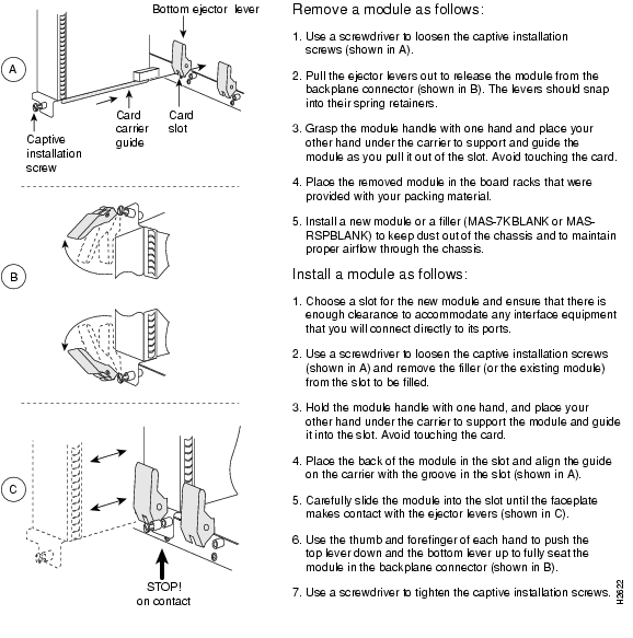
Depending on your configuration, you might need to insert additional or new processor modules in your Cisco 7505. To insert or remove interface processors, you do not need to turn off power to the system. However, you must turn off the system power before you insert or remove the RSP2, RSP4, or RSP8.
You need a number 1 Phillips or 3/16-inch flat-blade screwdriver to remove any fillers (blank processor carriers) and to tighten the captive installation screws that secure the processor module in its slot. Whenever you handle modules, you should use an ESD-preventive wrist strap or other grounding device to prevent ESD damage.
You can install interface processors (as shown in the following illustration) in any of the four interface processor slots, numbered 0 through 3 from bottom to top when viewing the chassis from the rear. (See the illustration of the Cisco 7505 in Figure 1-2.) The top slot (slot 4) must contain the RSP, which is a required system component. The processor carriers are keyed so you cannot incorrectly install them in the chassis slots.
Caution
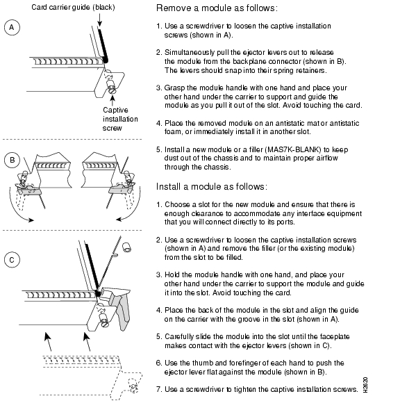
Figure 3-3 illustrates the procedures for removing and installing processor modules in the Cisco 7505.
Figure 3-3 Removing and Replacing Processor Modules (Cisco 7505)
Note
Cisco 7505 Installation Considerations
Before you install the Cisco 7505, decide where to install the router. If you intend to rack-mount the router, proceed to the "Rack-Mounting the Cisco 7505" section. If you do not intend to rack-mount the router, follow these steps to install the Cisco 7505 on a bench or tabletop:
Step 1
Step 2
Caution
Step 3
Step 4
Step 5
Step 6
Step 7
Step 8
Caution
Rack-Mounting the Cisco 7505
Before you begin the optional rack-mount installation, have the following tools and parts on hand:
•
•
•
•
•
•
•
Warning
The following guidelines are provided to ensure your safety:
–
–
–
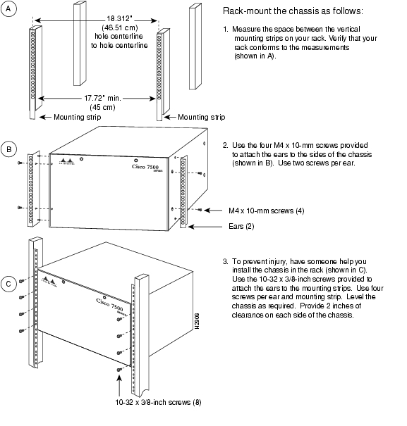
Figure 3-4 illustrates the Cisco 7505 rack-mount procedure.
Figure 3-4 Rack-Mounting the Cisco 7505
Attaching the Cisco 7505 Cable-Management Brackets
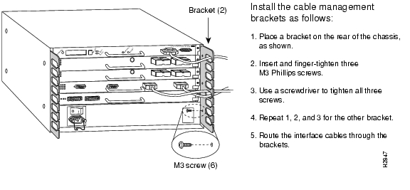
The cable-management brackets for the Cisco 7505 are designed to keep network interface cables untangled and orderly, and to prevent cables from hindering access to interface processors in the lower slots. Install the brackets before connecting network interface cables to the interface processor ports; otherwise, you will probably need to disconnect the cables to install the screws that secure the brackets.
The cable-management brackets attach to the interface processor end of the chassis.
To install the brackets, you need a number 1 Phillips screwdriver, two cable-management brackets, and six M3 x 8-mm Phillips panhead screws.
Follow the steps in Figure 3-5 to install the cable-management brackets on the Cisco 7505.
Figure 3-5 Installing Cable-Management Brackets (Cisco 7505)
If necessary, feed nylon or plastic cable ties through the holes provided in the brackets to secure small-gauge cables or cable bundles. Loop cables where possible, but do not exceed the recommended minimum bend radius for your optical-fiber cables.
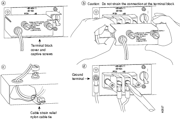
Connecting Power to the Cisco 7505 DC-Input Power Supply
This section includes the procedure for connecting power to the Cisco 7505 DC-input power supply. The DC-input power supply is already installed in the Cisco 7505 when you receive it. This procedure assumes you ordered a DC-input power supply with your Cisco 7505 and requires a twin-lead, 10-AWG cable for terminal block connections, a single 10-AWG wire for the ground connection, and a 3/16-inch flat-blade screwdriver to loosen all captive screws on the terminal block and terminal block cover.
Warning
Warning
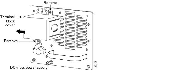
Use this procedure to connect power to a DC-input power supply in the Cisco 7505:
Step 1
Step 2
Step 3
Step 4
Step 5
Figure 3-6 Removing the Terminal Block Cover and Attaching Power Cables
Step 6
Step 7
Step 8
This completes the procedure for attaching DC-input cables to the Cisco 7505 DC-input power supply, as well as procedures required to install the Cisco 7505.
For information on how to connect cables to the RSP, see the "Making Cable Connections to the RSP" section, and then proceed to the "What Do I Do Now?" section.
Installing the Cisco 7507 and Cisco 7507-MX
This section provides procedures for installing your Cisco 7507 and Cisco 7507-MX and for connecting power cables to power supplies. Figure 3-7 illustrates the order of procedures to install the Cisco 7507 or Cisco 7507-MX router and connect cables. It also indicates the Cisco publications you should refer to for more detailed information.
Figure 3-7 Installation Flowchart (Cisco 7507 and Cisco 7507-MX)
Depending on your configuration, you might need to insert additional or new processor modules in your Cisco 7507 or Cisco 7507-MX. To insert or remove interface processors, you do not need to turn off power to the system. However, if the system is operating, you must turn off the system power before you insert or remove an RSP2, RSP4, or RSP8.
You need a number 1 Phillips or 3/16-inch flat-blade screwdriver to remove any fillers (blank processor module carriers) and to tighten the captive installation screws that secure the processor module in its slot. Whenever you handle modules, you should use an ESD-preventive wrist strap or other grounding device to prevent ESD damage.
You can install interface processors (as shown in the following figure) in any of the five interface processor slots, which are numbered 0 and 1, and 4 through 6, from left to right when viewing the chassis from the rear. (See Figure 1-5.) Slot 2 or slot 3 contains the RSP, which is a required system component.
Caution
Figure 3-8 illustrates the procedure for removing and replacing processor modules in the Cisco 7507 and Cisco 7507-MX.
Note
If you have a Cisco 7507 or Cisco 7507-MX with an RSP2 configured as the system slave, we strongly recommend that you use the following procedure to remove and replace an interface processor:
Step 1
Step 2
Step 3
Step 4
Step 5
Figure 3-8 Removing and Replacing Processor Modules— (Cisco 7507 and Cisco 7507-MX)
Note
Cisco 7507 and Cisco 7507-MX Installation Considerations
Before you install the Cisco 7507 or Cisco 7507-MX, decide where to install the router.
Note
On the rear of the chassis, do the following:
Step 1
Step 2
Step 3
Warning
Step 4
Caution
Step 5
Step 6
Step 7
After you correctly position the chassis, proceed to the next section, " Installing Cisco 7507 and Cisco 7507-MX Power Supplies."
Installing Cisco 7507 and Cisco 7507-MX Power Supplies
Your Cisco 7507 or Cisco 7507-MX was shipped with the power supplies removed. One power supply is shipped as standard equipment; a second power supply is optional. Install power supplies only after you have finally installed or rack-mounted the chassis.
Note
Warning
Always install the first power supply in the lower power supply bay and the second, if any, in the upper bay. In systems with dual power supplies and when separate power sources are available, connect each power supply to separate input lines, so in case of an input line failure, the second source will most likely still be available.
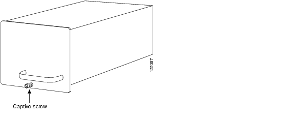
If you install a second power supply in the upper bay, use a screwdriver to loosen the captive screw and remove the cover plate. Save the plate and replace it whenever the system is operating with one power supply.
Warning
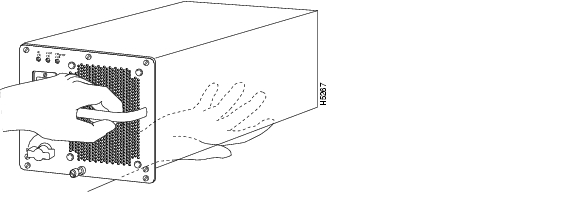
Following is the procedure for installing power supplies in the Cisco 7507 or Cisco 7507-MX:
Step 1
Step 2
Step 3
Figure 3-9 Handling a Power Supply (Cisco 7507 and Cisco 7507-MX AC-Input Power Supply Shown)
Caution
Step 4
Step 5
Caution
Step 6
Caution
Step 7
Note
Step 8
Step 9
Caution
If you are installing a second power supply, repeat Step 2 through Step 9. We recommend you connect the second power supply to a secondary power source for redundancy.
Note
Connecting Power to Cisco 7507 or Cisco 7507-MX DC-Input Power Supplies
This section includes the procedure for connecting power to the Cisco 7507 or Cisco 7507-MX DC-input power supplies.
The following procedure assumes you have already installed the power supplies using the procedure in the "Installing Cisco 7507 and Cisco 7507-MX Power Supplies" section. The procedure requires 8-AWG cable for terminal block connections and a 3/16-inch flat-blade screwdriver to loosen the captive screws on the terminal block cover and the terminal block.
Warning
Warning
Warning
Use this procedure to connect power to DC-input power supplies in the Cisco 7507 or Cisco 7507-MX:
Step 1
Step 2
Figure 3-10 Removing the Terminal Block Cover (Cisco 7507 and Cisco 7507-MX)
Step 3
Warning
Figure 3-11 Installing the Power Cable Leads, Nylon Ties, and Cover (Cisco 7507 and Cisco 7507-MX)
Warning
Warning
Step 4
Step 5
Warning
Warning
Step 6
Step 7
Note
This completes the procedure for attaching power cables to the DC-input power supplies in a Cisco 7507 or Cisco 7507-MX, as well as the procedures required to install the Cisco 7507 or Cisco 7507-MX.
For information on how to connect cables to the RSP, see the "Making Cable Connections to the RSP" section, and then proceed to the "What Do I Do Now?" section.
Installing the Cisco 7513, Cisco 7513-MX, and Cisco 7576
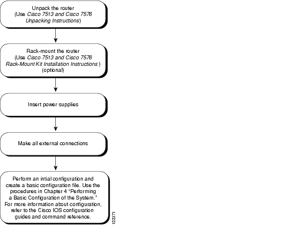
This section provides procedures for installing your Cisco 7513, Cisco 7513-MX, or Cisco 7576 and connecting power cables to power supplies. The flowchart in Figure 3-12 illustrates the recommended order of procedures to install a Cisco 7513, Cisco 7513-MX, or Cisco 7576 router. It also indicates the Cisco publications you should refer to for more detailed information.
Figure 3-12 Installation Flowchart (Cisco 7513, Cisco 7513-MX, and Cisco 7576)
Depending on your configuration, you might need to remove processor modules to reduce the weight of the chassis for rack-mount installation. To remove or insert interface processors, you do not need to turn off power to the system; however, on single power supply systems, you must turn off the system power before you insert or remove an RSP.
Note
You need a number 1 Phillips or 3/16-inch flat-blade screwdriver to remove any fillers (blank processor module carriers) and to tighten the captive installation screws that secure the processor module in its slot. Whenever you handle modules, you should use an ESD-preventive wrist strap or other grounding device to prevent ESD damage.
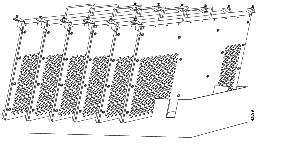
Figure 3-13 Temporary Storage for Removed Processor Modules
In the Cisco 7513 and Cisco 7513-MX you can install interface processors in any of the 11 interface processor slots, numbered 0 through 5 for CyBus 0, and 8 through 12 for CyBus 1, from left to right when viewing the chassis from the rear. Slot 6 and slot 7 are the RSP slots and are reserved for the RSP2, RSP4, or RSP8, which is a required system component. (See the illustration of the card cage and processor modules in Figure 1-11 in Chapter 1, "Cisco 7500 Series Product Overview.")
The backplane of the Cisco 7576 features two routers (router A and router B) on a single backplane. Router A consists of two CyBuses and uses interface processor slots 0 through 5, with an RSP4 (or RSP8) in slot 6. Router B also consists of two CyBuses. It uses interface processor slots 8 through 12, with an RSP4 (or RSP8) in slot 7. (See the illustration of the card cage and processor modules in Figure 1-17 in Chapter 1, "Cisco 7500 Series Product Overview.")
Caution
Caution
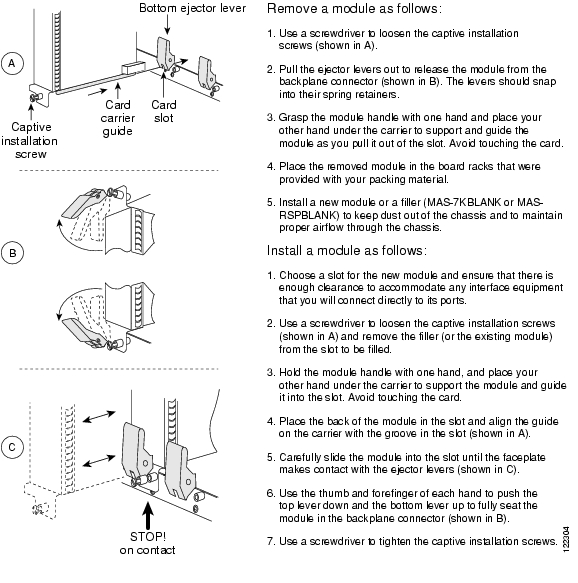
Figure 3-14 illustrates the procedures for removing and replacing processor modules in the Cisco 7513, Cisco 7513-MX, and Cisco 7576.
Note
Note
If you have a Cisco 7513 or Cisco 7513-MX with an RSP2 configured as the system slave, we strongly recommend that you use the following procedure to remove and replace an interface processor:
Step 1
Step 2
Step 3
Step 4
Step 5
Figure 3-14 Removing and Replacing Processor Modules (*Cisco 7513, Cisco 7513-MX, and Cisco 7576)
Note
Cisco 7513, Cisco 7513-MX, and Cisco 7576 Installation Considerations
The chassis should already be in the area where you will install it, and your installation location should already be determined.
Warning
The Cisco 7513, Cisco 7513-MX, and Cisco 7576 chassis weigh 160 lb (72.6 kg) fully configured and can be lifted by two people; however, to make the installation easier, consider removing components from the chassis.
Specifically, consider the following:
•
(To remove processor modules from the Cisco 7513, Cisco 7513-MX, or Cisco 7576, see Figure 3-14.)
•
(To remove the card cage assembly, see the "Removing and Replacing the Cisco 7513, Cisco 7513-MX, and Cisco 7576 Card Cage Assembly" section on page 7-5.)
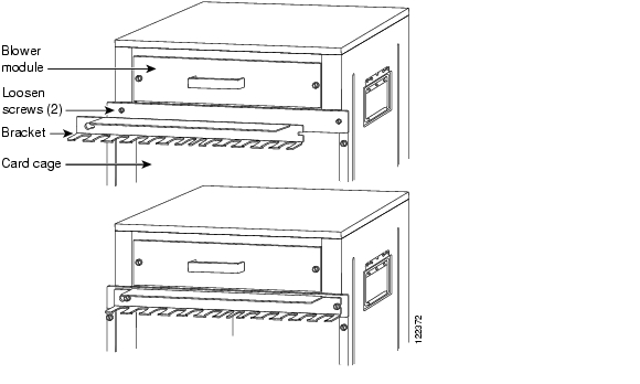
•
(To remove the blower assembly, see the "Removing and Replacing the Cisco 7513, Cisco 7513-MX, and Cisco 7576 Blower Module" section on page 7-10.)
•
(Power supplies are not installed when you receive your Cisco 7513, Cisco 7513-MX, or Cisco 7576. To install power supplies, see the "Installing Cisco 7513, Cisco 7513-MX, and Cisco 7576 Power Supplies" section.)
•
•
•
•
Warning
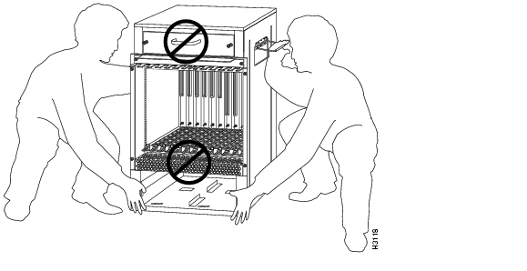
To prevent damage to the chassis, lift the chassis by placing one hand on a side handle and the other beneath the front of the chassis, as shown in Figure 3-15. Do not lift the chassis using the blower module handle or the air intake vent.
Figure 3-15 Lifting a Cisco 7513, Cisco 7513-MX, or Cisco 7576
Follow these steps to install the Cisco 7513, Cisco 7513-MX, and Cisco 7576:
Step 1
Step 2
Note
We do not recommend that you install the Cisco 7513, Cisco 7513-MX, or Cisco 7576 anywhere other than in a rack.
Warning
Step 3
Ensure that you temporarily have at least 2 to 3 feet (0.6 to 0.9 m) of clearance around the rear of the chassis. You will need this space to install the power supplies, perform maintenance on the chassis, and observe LED indications. After installation, this space can be reduced as required; however, maintain a minimum of 19 inches (48.3 cm) behind the chassis.
Step 4
Step 5
Step 6
This completes the procedure for installing the Cisco 7513, Cisco 7513-MX, and Cisco 7576. Proceed to the "Attaching the Cisco 7513, Cisco 7513-MX, and Cisco 7576 Cable-Management Bracket" section.
Attaching the Cisco 7513, Cisco 7513-MX, and Cisco 7576 Cable-Management Bracket
Use the following procedure to install the cable-management bracket. You will need a large flat-blade screwdriver for this procedure.
Step 1
Figure 3-16 Installing the Cable-Management Bracket on a Cisco 7513, Cisco 7513-MX, and Cisco 7576
Step 2
Step 3
Step 4
Note
It might be necessary to bundle longer cables to avoid tangling them. Do this at the cable-management bracket or at the rack, but leave enough room to remove processor modules and power supplies and to change cables as required. Do not block the power supply or chassis intake air vents with cables. Verify that the cables do not interfere with removal and installation of the blower module.This completes the procedure for installing the cable-management bracket. Proceed to the next section, " Installing Cisco 7513, Cisco 7513-MX, and Cisco 7576 Power Supplies."
Installing Cisco 7513, Cisco 7513-MX, and Cisco 7576 Power Supplies
Your Cisco 7513, Cisco 7513-MX, or Cisco 7576 was shipped with the power supplies removed. The Cisco 7513 and Cisco 7513-MX are shipped with one power supply as standard equipment; a second power supply is optional equipment. When purchased new (not upgraded), the Cisco 7576 comes with two AC-input power supplies as standard equipment. Install power supplies only after you have finally installed or rack-mounted the chassis.
Based on the NFPA 70 National Electrical Code, you should use a 35-amp (A) overcurrent protector to meet the requirement for the overcurrent protector size of 125 percent of the load current, which is approximately 27A. An overcurrent protector rated for 30A can be used only if it has been listed by the safety agency for operation at 100 percent of its rating.
Note
Follow this procedure to install a power supply in the Cisco 7513, Cisco 7513-MX, and Cisco 7576:
Step 1
Step 2
Step 3
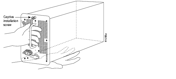
Figure 3-17 Handling a Power Supply (Cisco 7513, Cisco 7513-MX, and Cisco 7576 AC-Input Power Supply Shown)
Step 4
Figure 3-18 Installing a Power Supply (Cisco 7513, Cisco 7513-MX, and Cisco 7576 AC-Input Power Supply Shown)
Step 5
Note
Step 6
Step 7
Caution
Figure 3-19 Power Supply Blank (Cisco 7513, Cisco 7513-MX, and Cisco 7576)
If you are installing both power supplies, repeat Step 1 through Step 7 for the second power supply. To prevent system problems, do not mix AC-input and DC-input power supplies in the same chassis.
Connecting Power to Cisco 7513, Cisco 7513-MX, and Cisco 7576 DC-Input Power Supplies
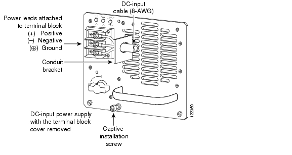
This procedure assumes you have already installed the power supplies using the procedure in the "Installing Cisco 7513, Cisco 7513-MX, and Cisco 7576 Power Supplies" section. The power supplies rest on the floor of the chassis under the card cage. This procedure requires an 8-mm nut driver and 8-AWG cable for power supply connections. The DC-input cable must be routed through conduit from your power source to the power supply.
Note
Warning
Warning
Warning
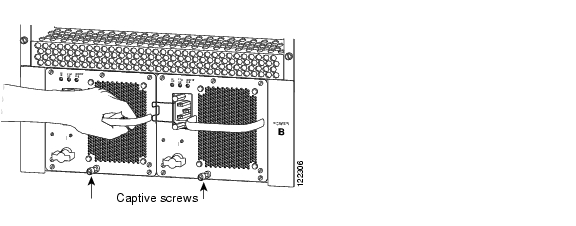
Use this procedure to connect power to DC-input power supplies in the Cisco 7513, Cisco 7513-MX, and Cisco 7576:
Step 1
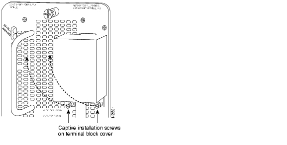
Step 2
Figure 3-20 Removing the Terminal Block Cover (Cisco 7513, Cisco 7513-MX, and Cisco 7576)
Step 3
Warning
Step 4
Step 5
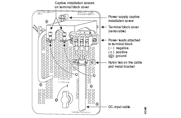
Warning
Figure 3-21 Attaching the DC-Input Power Cable (Cisco 7513, Cisco 7513-MX, and Cisco 7576)
Warning
Step 6
Step 7
Warning
Step 8
Warning
Step 9
If you plan to add a second power supply, repeat Step 1 through Step 9.
Note
This completes the procedures required to install the Cisco 7513, Cisco 7513-MX, and Cisco 7576.
For information on how to connect cables to the RSP, see the next section, " Making Cable Connections to the RSP,"and then proceed to the "What Do I Do Now?" section.
Making Cable Connections to the RSP
This section describes how to make cable connections to the console and auxiliary ports on the RSPs in the Cisco 7500 series routers. (Specific differences between RSPs are clearly noted.)
Note
Connecting a Console Terminal to the RSP
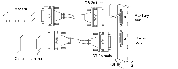
The system console port on the RSP is a DB-25 receptacle DCE port for connecting a data terminal, which will allow you to configure and communicate with your system. Use the console cable provided to connect the terminal to the console port on the RSP. The console port is located on the RSP next to the auxiliary port, as shown in Figure 3-22, and is labeled Console. (The RSP in the Cisco 7505 is oriented horizontally.)
Before connecting the console port, check your terminal's documentation to determine the baud rate of the terminal you will be using. The baud rate of the terminal must match the default baud rate (9600 baud). Set up the terminal as follows: 9600 baud, 8 data bits, no parity, and 2 stop bits (9600,8N2).
Figure 3-22 Console and Auxiliary Port Connections (All RSPs)
Note
Connecting to the Auxiliary Port
The auxiliary port on the RSP is a DB-25 plug DTE port for connecting a modem or other DCE device (such as a CSU/DSU or another router) to the router. The port is located next to the console port on the RSP and is labeled AUX. An example of a modem connection is shown in Figure 3-22.
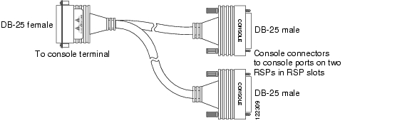
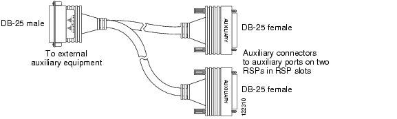
Using the Y-Cables for Console and Auxiliary Connections
For systems with two RSP2s, two RSP4s, two RSP8s, or one of each installed (one as master and one as slave in RSP slot 2 and slot 3 in the Cisco 7507, Cisco 7507-MX, and slot 6 and slot 7 in the Cisco 7513 and Cisco 7513-MX, using the HSA feature), you can simultaneously connect to both console or auxiliary ports using a special Y-cable. The RSP2, RSP4, or RSP8 defaults as the system master if only one is installed.
Note
Figure 3-22 shows the console Y-cable, and Figure 3-23 shows the auxiliary Y-cable.
Figure 3-23 Console Y-Cable—RSP2/RSP4/RSP8 (CAB-RSP2CON Shown)
Figure 3-24 Auxiliary Y-Cable—RSP2/RSP4/RSP8 (CAB-RSP2AUX Shown)
What Do I Do Now?
After you install your Cisco 7500 series router hardware, complete all power connections, and correctly attach a console terminal (and any other auxiliary equipment), you can connect the network interfaces in your Cisco 7500 series router to your external network using the appropriate Cisco-supplied and external cable vendor-supplied interface cables.
To connect the network interfaces, refer to one of the following:
•
–
–
–
–
–
–
–
–
The configuration note Second-Generation Versatile Interface Processor (VIP2) Installation and Configurationinclude the following information:
–
–
–
–
–
–
–
–
After you have connected all network interface cables, see "Performing a Basic Configuration of the System."
For more complete software and protocol configuration information, refer to the companion Cisco IOS software configuration publications, which are listed in the "If You Need More Configuration Information" section.
Note
![]()
![]()
![]()
![]()
![]()
![]()
![]()
![]()
Posted: Thu Mar 24 11:44:12 PST 2005
All contents are Copyright © 1992--2005 Cisco Systems, Inc. All rights reserved.
Important Notices and Privacy Statement.