|
|

Table Of Contents
Cisco 7500 Series Product Overview
Cisco 7505 System Specifications
Cisco 7507 Dual CyBus Backplane
Cisco 7507 System Specifications
Cisco 7507-MX Dual CyBus Backplane
Cisco 7507-MX System Specifications
Cisco 7513 Dual CyBus Backplane
Cisco 7513 System Specifications
Cisco 7513-MX Dual CyBus Backplane
Cisco 7513-MX System Specifications
Cisco 7576 Dual CyBus Backplane
Identifying Cisco 7576 Independent Routers and CyBuses
Cisco 7576 System Specifications
Route Switch Processor Overview
RSP-Specific Hardware Features
AC-Input and DC-Input Power Supply Overview
Fan Tray and Blower Assembly Overview
Cisco 7507 and Cisco 7507-MX Blower Assembly
Cisco 7513, Cisco 7513-MX, and Cisco 7576 Blower Module Assembly
Cisco 7500 Series Product Overview
The Cisco 7500 series includes the following routers: Cisco 7505, Cisco 7507, Cisco 7507-MX, Cisco 7513, Cisco 7513-MX, and Cisco 7576. The Cisco 7500 series routers support multiprotocol, multimedia routing and bridging with a wide variety of protocols and any combination of ATM, BRI, channel attachment, channelized E1, T1, and T3, Ethernet, Fast Ethernet, FDDI, HSSI, multichannel, PRI, Packet over SONET, synchronous serial, Token Ring, and voice media.
The first six sections of this chapter describe the Cisco 7500 series routers, and include the following:
Note
The Cisco 7513, Cisco 7513-MX, and the Cisco 7576 are similar in appearance. To determine which router you have, look at the slot numbering label on the back of the unit. The Cisco 7513-MX and Cisco 7576 are identified as such on the slot numbering label.
The remaining sections of this chapter describe components in the Cisco 7500 series routers, which are considered to be standard equipment and ship with each router:
•
•
•
•
This section provides a general overview of interface processors; for a complete discussion and description of all interface processors available for the Cisco 7500 series routers, refer to the companion publication Interface Processor Installation and Configuration Guide.
Terms and Acronyms
Following is a list of acronyms, initializations, and terms that identify the Cisco 7500 series system components and features:
•
•
•
•
•
•
•
•
•
•
•
•
•
•
•
•
•
•
•
•
•
•
•
•
•
•
•
•
•
•
•
•
•
•
•
•
•
Cisco 7505 Overview
The Cisco 7505 supports multiprotocol, multimedia routing and bridging with a wide variety of protocols and any combination of available electrical interfaces and media. Network interfaces reside on interface processors that provide a direct connection between the CyBus in your Cisco 7505 and external networks.
The Cisco 7505 has five slots: four interface processor slots (0 through 3) and one slot for the Route Switch Processor (RSP2, RSP4/4+, or RSP8). The Cisco 7505 supports 4 VIPs, one for each interface processor slot. The Cisco 7505 uses a single power supply, with two models available: DC input or AC input.
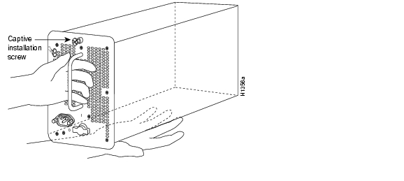
The front, or noninterface processor end, of the Cisco 7505 has a removable panel that is secured with two captive fasteners. See Figure 1-1. Removing the panel provides access to the internal components: the power supply and fan tray.
Figure 1-1 Cisco 7505 (Front View)
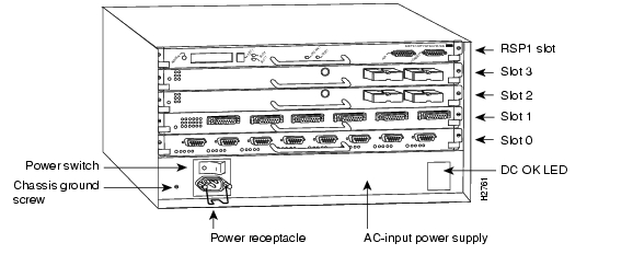
Figure 1-2 shows details of the rear, interface-processor end of the Cisco 7505.
Figure 1-2 Cisco 7505 (Rear View)
Cisco 7505 CyBus Backplane
The CyBus backplane in the Cisco 7505 provides the physical connections for the RSPs and interface processors, and transfers information at up to 1.067 Gbps.
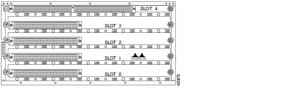
The Cisco 7505 CyBus backplane has five slots: interface processor slots 0 through 3, and one slot for the RSP (RSP2, RSP4/4+, or RSP8), as shown in Figure 1-3.
Figure 1-3 CyBus Backplane in the Cisco 7505
The backplane slots are keyed so that the processor modules can be installed only in the slots designated for them. Keys on the backplane fit into two key guides on each module. Although the RSP uses unique keys, all four interface processor slots use the same key, so you can install an interface processor in any interface processor slot, but not in the RSP slot.
Caution
Cisco 7505 System Specifications
Table 1-1 lists the specifications for the Cisco 7505 system.
Cisco 7507 Overview
The Cisco 7507 supports multiprotocol, multimedia routing and bridging with a wide variety of protocols and any combination of available electrical interfaces and media.
Network interfaces reside on interface processors that provide a direct connection between the two CyBuses in the Cisco 7507 and your external networks. The Cisco 7507 has seven slots: interface processor slots 0 and 1, Route Switch Processor (RSP2, RSP4/4+, RSP8, or RSP16) slots 2 and 3, and interface processor slots 4 through 6. The Cisco 7507 supports 5 VIPs, one for each interface processor slot.
There are bays for up to two AC-input or DC-input power supplies. The chassis will operate with one power supply. Although a second power supply is not required, it allows load sharing and increased system availability.
Caution
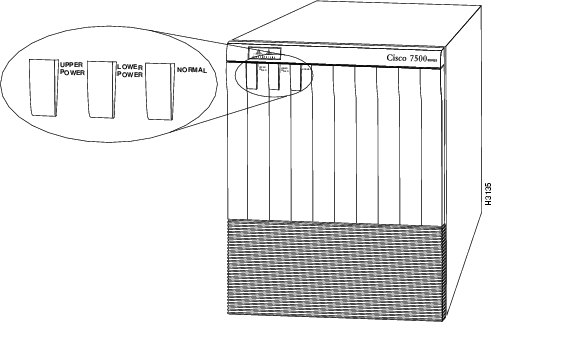
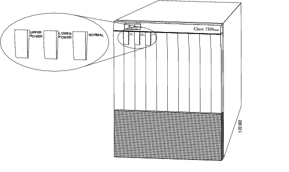
The Cisco 7507 front panel, shown in Figure 1-4, contains three status indicators and two removable panels for access to the internal components. The three light emitting diodes (LEDs) on the front panel indicate normal system operation and the currently active power supplies. On the back of the router, a normal LED on the RSP and LEDs on the power supplies indicate the same status.
Figure 1-4 Cisco 7507 (Front View)
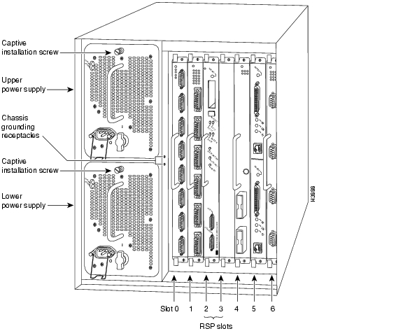
Figure 1-5 shows details on the rear, interface-processor end of the Cisco 7507.
Figure 1-5 Cisco 7507 (Rear View)
Cisco 7507 Dual CyBus Backplane
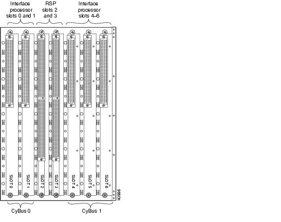
The dual CyBus backplane provides the physical connections for the RSPs and interface processors, and transfers information at up to 2.134 Gbps (1.067 Gbps per CyBus). The dual CyBus has seven slots: interface processor slots 0 and 1 (CyBus 0), RSP slots 2 and 3, and interface processor slots 4 through 6 (CyBus 1), as shown in Figure 1-6.
Figure 1-6 Dual CyBus Backplane in the Cisco 7507
An RSP2, RSP4/4+, RSP8, or RSP 16 in either slot 2 or slot 3 controls both CyBus 0 and CyBus 1. The dual CyBus backplane in the Cisco 7507 has an aggregate bandwidth of 2.134 Gbps. The two CyBuses are independent of one another. Interface processors connected to one CyBus are unaffected by the traffic generated by the interface processors connected to the other.
The backplane slots are keyed so that the processor modules can be installed only in the slots designated for them. Keys on the backplane fit into two key guides on each module. Although the RSP uses unique keys, all five interface processor slots use the same key, so you can install an interface processor in any interface processor slot, but not in the RSP slot.
Cisco 7507 System Specifications
Table 1-2 lists the specifications for the Cisco 7507 system.
Cisco 7507-MX Overview
The Cisco 7507-MX supports multiprotocol, multimedia routing and bridging with a wide variety of protocols and any combination of available electrical interfaces and media.
Network interfaces reside on interface processors that provide a direct connection between the two CyBuses in the Cisco 7507-MX and your external networks. The Cisco 7507-MX has seven slots: interface processor slots 0 and 1, Route Switch Processor (RSP2, RSP4/4+, RSP8, or RSP16) slots 2 and 3, and interface processor slots 4 through 6. The Cisco 7507-MX supports 5 VIPs, one for each interface processor slot.
There are bays for up to two AC-input or DC-input power supplies. The chassis will operate with one power supply. Although a second power supply is not required, it allows load sharing and increased system availability.
Caution
The Cisco 7507-MX front panel, shown in Figure 1-7, contains three status indicators and two removable panels for access to the internal components. The three light emitting diodes (LEDs) on the front panel indicate normal system operation and the currently active power supplies. On the back of the router, a normal LED on the RSP and LEDs on the power supplies indicate the same status.
Figure 1-7 Cisco 7507-MX (Front View)
Figure 1-8 shows details on the rear, interface-processor end of the Cisco 7507-MX.
Figure 1-8 Cisco 7507-MX (Rear View)
Cisco 7507-MX Dual CyBus Backplane
The dual CyBus backplane provides the physical connections for the RSPs and interface processors, and transfers information at up to 2.134 Gbps (1.067 Gbps per CyBus). The dual CyBus has seven slots: interface processor slots 0 and 1 (CyBus 0), RSP slots 2 and 3, and interface processor slots 4 through 6 (CyBus 1), as shown in Figure 1-9.
Figure 1-9 Dual CyBus Backplane in the Cisco 7507-MX
Note
An RSP2, RSP4/4+, or RSP8 in either slot 2 or slot 3 controls both CyBus 0 and CyBus 1. The dual CyBus backplane in the Cisco 7507-MX has an aggregate bandwidth of 2.134 Gbps. The two CyBuses are independent of one another. Interface processors connected to one CyBus are unaffected by the traffic generated by the interface processors connected to the other.
The backplane slots are keyed so that the processor modules can be installed only in the slots designated for them. Keys on the backplane fit into two key guides on each module. Although the RSP uses unique keys, all five interface processor slots use the same key, so you can install an interface processor in any interface processor slot, but not in the RSP slot.
Cisco 7507-MX System Specifications
Table 1-3 lists the specifications for the Cisco 7507-MX system.
Cisco 7513 Overview
The Cisco 7513 router supports multiprotocol, multimedia routing and bridging with a wide variety of protocols and any combination of available electrical interfaces and media. Network interfaces reside on interface processors that provide a direct connection between the two CyBuses in the Cisco 7513 and your external networks. The Cisco 7513 has 13 slots: interface processor slots 0 through 5, Route Switch Processor (RSP2, RSP4/4+, RSP8, or RSP16) slots 6 and 7, and interface processor slots 8 through 12. The Cisco 7513 supports 11 VIPs, one for each interface processor slot.
There are bays for up to two AC-input or DC-input power supplies. The chassis will operate with one power supply. Although a second power supply is not required, it allows load sharing and increased system availability.
Caution
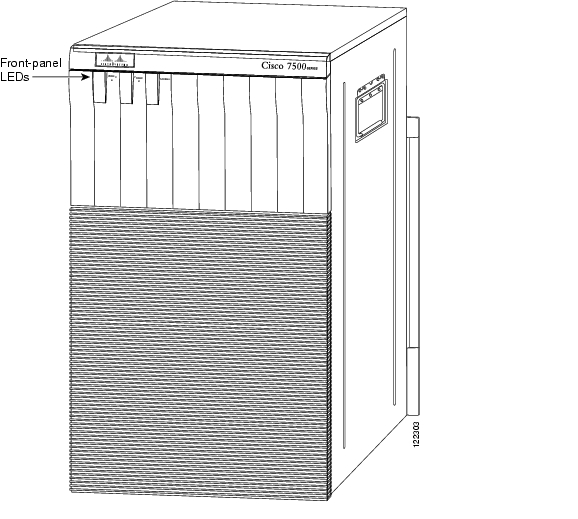
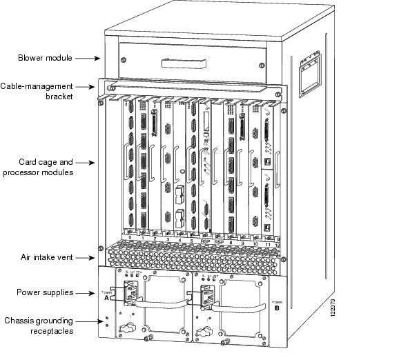
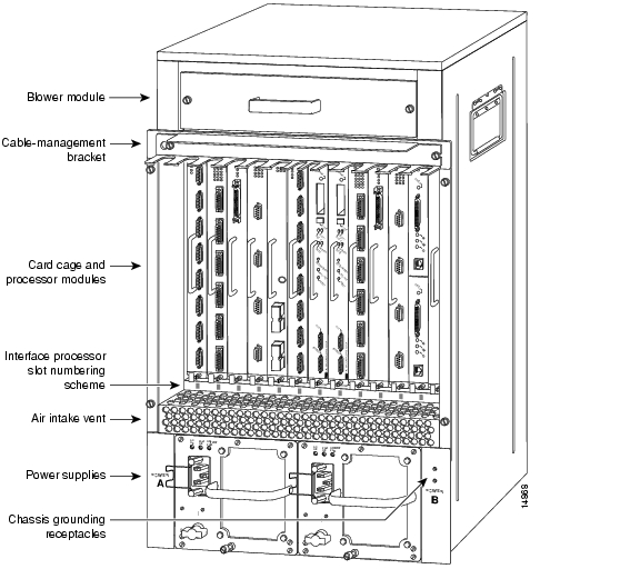
The Cisco 7513 is shown in Figure 1-10. The three front-panel LEDs indicate system and power supply status, and
Figure 1-10 Cisco 7513 (Front View)
Figure 1-11 shows details on the rear, interface-processor end of the Cisco 7513.
Figure 1-11 Cisco 7513 (Rear View)
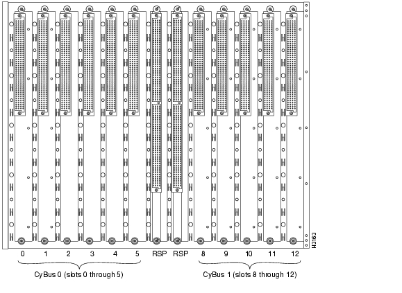
Cisco 7513 Dual CyBus Backplane
The dual CyBus backplane, located at the rear of the Cisco 7513 removable card cage, provides the physical connections for the RSPs and interface processors, and transfers information at up to 2.134 Gbps (1.067 Gbps per CyBus).
The dual CyBus has 13 slots: interface processor slots 0 through 5 (CyBus 0); two RSP slots (slots 6 and 7); interface processor slots 8 through 12 (CyBus 1), as shown in Figure 1-12.
Figure 1-12 Dual CyBus Backplane in the Cisco 7513
An RSP2, RSP4/4+, or RSP8 in either slot 6 or slot 7 controls both CyBus 0 and CyBus 1. The dual CyBus backplane in the Cisco 7513 has an aggregate bandwidth of 2.134 Gbps. Interface processors connected to one CyBus are unaffected by the traffic generated by the interface processors connected to the other CyBus. The two CyBuses are independent of one another.
The backplane slots are keyed so that the processor modules can be installed only in the slots designated for them. Keys on the backplane fit into two key guides on each module. Although the RSP uses unique keys, all eleven interface processor slots use the same key, so you can install an interface processor in any interface processor slot, but not in the RSP slot.
Note
Cisco 7513 System Specifications
Table 1-4 lists the specifications for the Cisco 7513 system.
Table 1-4 Cisco 7513 Specifications
Backplane
Two 1.0677-Gbps CyBuses, 11 interface processor slots, 2 RSP slots
Dimensions
(H x W x D)33.75 x 17.5 x 22 in. (85.73 x 44.45 x 55.88 cm)
Chassis width including rack-mount flanges is 18.93 in. (48.1 cm)
Chassis depth including power cables and cable-management bracket: 24 in. (60.96 cm)Weight
Chassis with blower module: 75 lb (34.02 kg)
Chassis with blower module and 1 power supply: 100 lb (45.36 kg)
Chassis with blower module and 2 power supplies: 125 lb (56.7 kg)
Chassis with blower module, 2 power supplies, and all slots filled: ~160 lb (72.58 kg), each processor module weighs ~2.5 lb (1.13 kg)Power dissipation
1600W with a maximum configuration and 1 AC-input power supply
1600W with a maximum configuration and 1 DC-input power supply
1700W nominal with a maximum configuration and either 2 AC-input or 2 DC-input power suppliesHeat dissipation
1600W (5461 Btu/hr)
AC-input voltage
100 to 240 VAC
Frequency
50/60 Hz
AC-input cable1
12 AWG, with 3 leads, an IEC-320 plug on the router end, and a country-dependent plug on the power source end
AC-input voltage
and current100 VAC at 16 amps (A) maximum, wide input with power factor corrector (PFC)
240 VAC at 7A maximumDC-input voltage and current
-48 VDC nominal at 35A in North America
(-60 VDC at 35A in the European Union)DC-input cable
8 AWG (recommended minimum), with 3 leads and rated for at least 194°F (90°C) (you supply the cable)
Power distribution
+5.2 VDC @ 75A, +12 VDC @ 15A, -12 VDC @ 3A, +24 VDC @ 5A
Airflow/noise level
Bottom to top through chassis by variable-speed blower (62 to 70 dBA)
Temperature
32 to 104°F (0 to 40°C), operating; -4 to 149°F (-20 to 65°C), nonoperating
Relative humidity
10 to 90%, noncondensing
Software requirement
RSP2 - Cisco IOS Release 10.3(6) or a later release of 10.3
RSP4/4+ - Cisco IOS Release 11.1(8)CA or a later release of 11.1
RSP8 - Cisco IOS Release 12.0(9)S or a later release of 12.0 S
RSP16 - Cisco IOS Release 12.1(12)E and later and Cisco IOS 12.0(21.02)S and laterAgency approvals
Safety: UL 1950, CSA 22.2-950, EN60950, EN41003, TS001, AS/NZS 3260
EMI: FCC Class A, EN60555-2, EN55022 Class B, VDE 0878 Part 3, 30 Class B Immunity: EN55101/2 (ESD), EN55101/3 (RFI), EN55101/4 (Burst), EN55101/5 (Surge), EN55101/6 (Conducted), IEC77B (AC Disturbance)
1 The Cisco 7513 requires a minimum of 20A service with a 20A receptacle at the power source. The power cable supplied with the Cisco 7513 uses a 20A male plug.
Cisco 7513-MX Overview
The Cisco 7513-MX router supports multiprotocol, multimedia routing and bridging with a wide variety of protocols and any combination of available electrical interfaces and media. Network interfaces reside on interface processors that provide a direct connection between the two CyBuses in the Cisco 7513-MX and your external networks. The Cisco 7513-MX has 13 slots: interface processor slots 0 through 5, Route Switch Processor (RSP2, RSP4/4+, RSP8, or RSP16) slots 6 and 7, and interface processor slots 8 through 12. The Cisco 7513-MX supports 11 VIPs, one for each interface processor slot.
There are bays for up to two AC-input or DC-input power supplies. The chassis will operate with one power supply. Although a second power supply is not required, it allows load sharing and increased system availability.
Caution
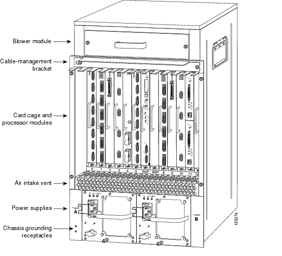
The Cisco 7513-MX is shown in Figure 1-13. The three front-panel LEDs indicate system and power supply status, and
Figure 1-13 Cisco 7513-MX (Front View)
Figure 1-14 shows details on the rear, interface-processor end of the Cisco 7513-MX.
Figure 1-14 Cisco 7513-MX (Rear View)
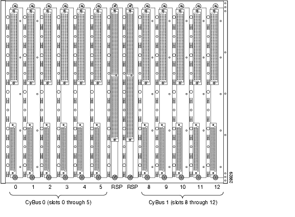
Cisco 7513-MX Dual CyBus Backplane
The dual CyBus backplane, located at the rear of the Cisco 7513-MX removable card cage, provides the physical connections for the RSPs and interface processors, and transfers information at up to 2.134 Gbps (1.067 Gbps per CyBus).
The dual CyBus has 13 slots: interface processor slots 0 through 5 (CyBus 0); two RSP slots (slots 6 and 7); interface processor slots 8 through 12 (CyBus 1), as shown in Figure 1-15.
Figure 1-15 Dual CyBus Backplane in the Cisco 7513-MX
Note
An RSP2, RSP4/4+, or RSP8 in either slot 6 or slot 7 controls both CyBus 0 and CyBus 1. The dual CyBus backplane in the Cisco 7513-MX has an aggregate bandwidth of 2.134 Gbps. Interface processors connected to one CyBus are unaffected by the traffic generated by the interface processors connected to the other CyBus. The two CyBuses are independent of one another.
The backplane slots are keyed so that the processor modules can be installed only in the slots designated for them. Keys on the backplane fit into two key guides on each module. Although the RSP uses unique keys, all eleven interface processor slots use the same key, so you can install an interface processor in any interface processor slot, but not in the RSP slot.
Note
Cisco 7513-MX System Specifications
Table 1-5 lists the specifications for the Cisco 7513-MX system.
Table 1-5 Cisco 7513-MX Specifications
Backplane
Two 1.0677-Gbps CyBuses: 11 interface processor slots, 2 RSP slots
Dimensions
(H x W x D)33.75 x 17.5 x 22 in. (85.73 x 44.45 x 55.88 cm)
Chassis width including rack-mount flanges is 18.93 in. (48.1 cm)
Chassis depth including power cables and cable-management bracket is 24 in. (60.96 cm)Weight
Chassis with blower module: 75 lb (34.02 kg)
Chassis with blower module and 1 power supply: 100 lb (45.36 kg)
Chassis with blower module and 2 power supplies: 125 lb (56.7 kg)
Chassis with blower module, 2 power supplies, and all slots filled: ~160 lb (72.58 kg), each processor module weighs ~2.5 lb (1.13 kg)Power dissipation
1600W with a maximum configuration and 1 AC-input power supply
1600W with a maximum configuration and 1 DC-input power supply
1700W nominal with a maximum configuration and either 2 AC-input or 2 DC-input power suppliesHeat dissipation
1600W (5461 Btu/hr)
AC-input voltage
100 to 240 VAC
Frequency
50/60 Hz
AC-input cable1
12 AWG, with 3 leads, an IEC-320 plug on the router end, and a country-dependent plug on the power source end
AC-input voltage
and current100 VAC at 16 amps (A) maximum, wide input with power factor corrector (PFC)
240 VAC at 7A maximumDC-input voltage and current
-48 VDC nominal at 35A in North America (-60 VDC at 35A in the European Union)
DC-input cable
8 AWG (recommended minimum), with 3 leads and rated for at least 194°F (90°C) (you supply the cable)
Power distribution
+5.2 VDC @ 75A, +12 VDC @ 15A, -12 VDC @ 3A, +24 VDC @ 5A
Airflow/noise level
Bottom to top through chassis by variable-speed blower (62 to 70 dBA)
Temperature
32 to 104°F (0 to 40°C), operating; -4 to 149°F (-20 to 65°C), nonoperating
Relative humidity
10 to 90%, noncondensing
Software requirement
RSP2 - Cisco IOS Release 10.3(6) or a later release of 10.3
RSP4/4+ - Cisco IOS Release 11.1(8)CA or a later release of 11.1
RSP8 - Cisco IOS Release 12.0(9)S or a later release of 12.0 S
RSP16 - Cisco IOS Release 12.1(12)E and later and Cisco IOS 12.0(21.02)S and laterAgency approvals
Safety: UL 1950, CSA 22.2-950, EN60950, EN41003, TS001, AS/NZS 3260
EMI: FCC Class A, EN60555-2, EN55022 Class B, VDE 0878 Part 3, 30 Class B
Immunity: EN55101/2 (ESD), EN55101/3 (RFI), EN55101/4 (Burst), EN55101/5 (Surge), EN55101/6 (Conducted), IEC77B (AC Disturbance)
1 The Cisco 7513-MX requires a minimum of 20A service with a 20A receptacle at the power source. The power cable supplied with the Cisco 7513-MX uses a 20A male plug.
Cisco 7576 Overview
The Cisco 7576 router supports multiprotocol, multimedia routing and bridging with a wide variety of protocols and any combination of available electrical interfaces and media. The Cisco 7576 consists of two independent Cisco 7500 series routers configured on a single split backplane. This system is housed within the chassis footprint of a Cisco 7513 router.
Network interfaces reside on interface processors that provide a direct connection between the two independent dual CyBuses located on the backplane of the Cisco 7576 and your external networks. The two independent dual CyBuses facilitate the configuration of two independent routers on a single backplane. These routers are identified as router A and router B.
The backplane of the Cisco 7576 has 13 slots. Router A uses interface processor slots 0 through 5 with a Route Switch Processor (RSP4/4+ or RSP8) in slot 6. Router B uses interface processor slots 8 through 12 with a Route Switch Processor (RSP4/4+ or RSP8) in slot 7. The Cisco 7576 supports 10 VIPs, one for each interface processor slot; 6 VIPs are supported in Router A and 5 VIPs are supported in Router B.
There are bays for up to two AC-input or DC-input power supplies. The chassis will operate with one power supply. Although a second power supply is not required, it allows load sharing and increased system availability.
Caution
Note
Figure 1-16 shows the front view of the Cisco 7576. The three front-panel LEDs indicate system and power supply status, and
Figure 1-16 Cisco 7576 (Front View)
Figure 1-17 shows details on the rear, interface-processor end of the Cisco 7576.
Figure 1-17 Cisco 7576 (Rear View)
Note
Cisco 7576 Dual CyBus Backplane
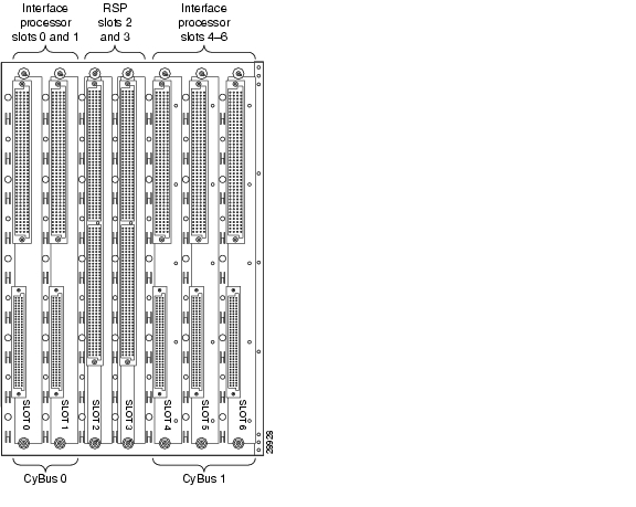
The Cisco 7576 features two dual CyBuses, creating two independent routers on one split backplane. The dual CyBus backplane, located at the rear of the removable card cage, provides the physical connections for the RSPs and interface processors, and transfers information at up to 2.134 Gbps (1.067 Gbps per CyBus) per router.
An RSP4/4+ or RSP8 in slot 6 controls router A and both CyBus 0 and CyBus 1. An RSP4/4+ or RSP8 in slot 7 controls router B and both CyBus 2 and CyBus 3. The dual CyBus backplane in the Cisco 7576 has an aggregate bandwidth of 2.134 Gbps per router. Interface processors connected to the set of CyBuses on router A are unaffected by the traffic generated by the interface processors connected to the set of CyBuses on router B. The dual CyBuses assigned to router A are independent of the dual CyBuses assigned to router B.
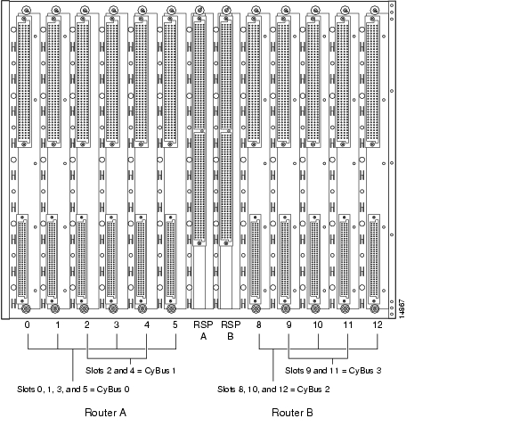
Figure 1-18 shows the details of the dual CyBus backplane.
Figure 1-18 Cisco 7576 Dual CyBus Backplane
Note
The backplane slots are keyed so that the processor modules can be installed only in the slots designated for them. Keys on the backplane fit into two key guides on each module. Although the RSP uses unique keys, all 11 interface processor slots use the same key, so you can install an interface processor in any interface processor slot, but not in the RSP slot.
For maintenance information about the card cage assembly, see the "Removing and Replacing the Cisco 7513, Cisco 7513-MX, and Cisco 7576 Card Cage Assembly" section on page 7-5.
Identifying Cisco 7576 Independent Routers and CyBuses
The Cisco 7576 dual CyBus backplane includes 13 slots and provides two independent routers on a split backplane, designated router A and router B.
The interface processor slot numbering scheme (see Figure 1-19) on the card cage of the Cisco 7576 provides easy identification of the independent routers, CyBuses, and slots that make up the Cisco 7576 backplane. The scheme uses color coding to help you differentiate between the independent router and CyBus assignments.
•
–
–
–
•
–
–
–
Figure 1-19 Enlarged View of the Cisco 7576 Interface Processor Slot Numbering Scheme
Note
CyBus Slot Number Assignments
The slot number assignments of the independent router CyBuses are separated by design. This facilitates automatic distribution of the system load across the CyBuses as interface processors are added. This design also provides better electrical flow and improves signal timing on the backplane.
Caution
Cisco 7576 System Specifications
Table 1-6 lists the specifications for the Cisco 7576 system.
Table 1-6 Cisco 7576 Specifications
Backplane
Four 1.0677-Gbps CyBuses divided into sets of 2 creating 2 independent routers: 6 interface processor slots and 1 RSP slot designated as router A, and 5 interface processor slots and 1 RSP slot designated as router B
Dimensions
(H x W x D)33.75 x 17.5 x 22 in. (85.73 x 44.45 x 55.88 cm)
Chassis width including rack-mount flanges is 18.93 in. (48.1 cm)
Chassis depth including power cables and cable-management bracket is 24 in. (60.96 cm)Weight
Chassis with blower module: 75 lb (34.02 kg)
Chassis with blower module and 1 power supply: 100 lb (45.36 kg)
Chassis with blower module and 2 power supplies: 125 lb (56.7 kg)
Chassis with blower module, 2 power supplies, and all slots filled: ~160 lb (72.58 kg), each processor module weighs ~2.5 lb (1.13 kg)Power dissipation
1600W with a maximum configuration and 1 AC-input power supply
1600W with a maximum configuration and 1 DC-input power supply
1700W nominal with a maximum configuration and either 2 AC-input or 2 DC-input power suppliesHeat dissipation
1600W (5461 Btu/hr)
AC-input voltage
100 to 240 VAC
Frequency
50/60 Hz
AC-input cable1
12 AWG, with 3 leads, an IEC-320 plug on the router end, and a country-dependent plug on the power source end
AC-input voltage
and current100 VAC at 16 amps (A) maximum, wide input with power factor correction (PFC)
240 VAC at 7A maximumDC-input voltage and current
-48 VDC nominal at 35A in North America
(-60 VDC at 35A in the European Union)DC-input cable
8 AWG (recommended minimum), with 3 leads and rated for at least 194°F (90°C) (you supply the cable)
Power distribution
+5.2 VDC @ 75A, +12 VDC @ 15A, -12 VDC @ 3A, +24 VDC @ 5A
Airflow/noise level
Bottom to top through chassis by variable-speed blower (62 to 70 dBA)
Temperature
32 to 104°F (0 to 40°C), operating; -4 to 149°F (-20 to 65°C), nonoperating
Relative humidity
10 to 90%, noncondensing
Software requirement
RSP4/4+ - Cisco IOS Release 11.1(22)CC, or a later release of 11.1
RSP8 - Cisco IOS Release 12.0(9)S or a later release of 12.0 SAgency approvals
Safety: UL 1950, CSA 22.2-950, EN60950, EN41003, TS001, AS/NZS 3260
EMI: FCC Class A, EN60555-2, EN55022 Class B, VDE 0878 Part 3, 30 Class B Immunity: EN55101/2 (ESD), EN55101/3 (RFI), EN55101/4 (Burst), EN55101/5 (Surge), EN55101/6 (Conducted), IEC77B (AC Disturbance)
1 The Cisco 7576 requires a minimum of 20A service with a 20A receptacle at the power source. The power cable supplied with the Cisco 7576 uses a 20A male plug.
Route Switch Processor Overview
The main system processor in the Cisco 7500 series routers is the Route Switch Processor (RSP). The current RSP models sold are: RSP4+, RSP8 and RSP16.. The RSP1, RSP2 and RSP4 are legacy models. For more information on any of these products, refer to http://www.cisco.com/univercd/cc/td/doc/product/core/cis7505/rte_swit/index.htm for additional information on these models. The RSPs have common hardware features, and hardware features that differentiate one from the other.
The following sections first describe hardware features that are specific to each RSP model, and then describe features that are common to all RSPs.
RSP-Specific Hardware Features
The following sections describe hardware features that are specific to each of the RSPs used in the Cisco 7500 series. Select the appropriate section based on the RSP and Cisco 7500 series router that you have:
•
•
•
RSP2—Cisco 7505
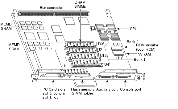
The RSP2, shown in Figure 1-20, is the main system processor for the Cisco 7505 router, and provides switched routing and high-speed switching functions.
The RSP2 is installed in the top slot in the Cisco 7505, which is labeled Slot 4 on the backplane and RSP to the left of the slots. (See Figure 1-3.) An RSP4 can also be used in the Cisco 7505. (See the "RSP4/4+—Cisco 7507, Cisco 7513, and Cisco 7576" section.) An RSP8 can also be used in the Cisco 7505. (See the "RSP8—Cisco 7507-MX and Cisco 7513-MX" section.)
Figure 1-20 Route Switch Processor (RSP2)
The RSP2 contains the system CPU, the system software (in Flash memory), the system memory components, and two PC Card slots, formerly called Personal Computer Memory Card International Association (PCMCIA) slots, and it maintains and executes the management functions that control the system.
Although no monitoring of ±12V or temperature is done by the RSP2, a comparator device ensures that ±12V is maintained within the normal operating ranges, and three temperature sensors on the RSP2 send temperature information to the chassis interface (CI) card. The CI card reports all voltage and temperature readings, and these readings are available through standard software commands for environmental monitoring.
The RSP2 uses a software-controlled configuration register, so you do not have to remove the RSP2 to configure jumpers. There are no user-configurable jumpers on the RSP2.
The RSP2 contains the following components:
•
•
•
In addition to the system software, the RSP2 contains and executes the following management functions that control the system:
•
•
•
•
•
The RSP2 supports high system availability (HSA), which is a feature in Cisco IOS Release 11.1(4) or later, allowing two RSPs to be used in a Cisco 7507, Cisco 7507-MX, Cisco 7513, or Cisco 7513-MX router.
Note
The RSP2 ships as Product Numbers RSP2 and RSP2=.
The RSP2 contains most of the memory components used by the system. Table 1-7 lists the functions of each type of memory on the RSP2.
Table 1-7 RSP2 Memory Components
DRAM
16 to 128 MB
2 to 4
8-, 16-, or 32-MB SIMMs (based on maximum DRAM required)
U21 and U33
U12 and U4SRAM
1 MB (fixed)
-
SRAM for packet buffering functions (MEMD)
-
512 KB (fixed)
-
SRAM for secondary CPU cache memory functions
-
NVRAM
128 KB
1
Nonvolatile SRAM for the system configuration file1
U18
Flash Memory:
SIMMPC Cards
8 MB
1
Contains the Cisco IOS images on the RSP2.
U18, 16, and 20 MB2
Up to 2
Contains the Cisco IOS images on up to 2
PC CardsSlot 0 and slot 1
Boot ROM3
256 KB
1
EPROM for the ROM monitor program
U30
1 A system configuration file is contained in NVRAM, which allows the Cisco IOS software to control several system variables.
2 Only Intel Series 2 Flash memory cards can be used with the RSP2.
3 With the RSP2, the HSA feature requires boot ROM Version 11.1(2) or later.
Note
RSP4/4+—Cisco 7507, Cisco 7513, and Cisco 7576
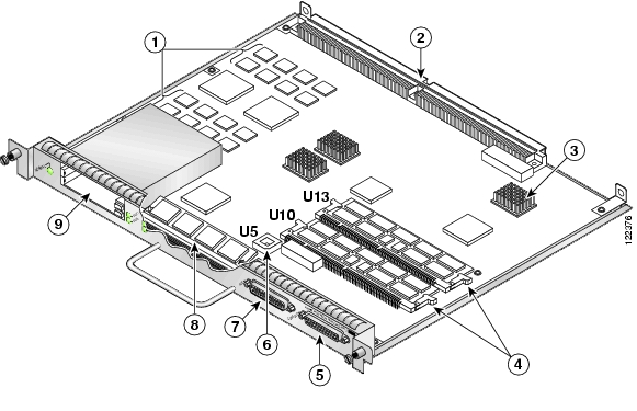
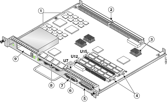
The RSP4/4+ shown in Figure 1-21, is the main system processor for the Cisco 7507, Cisco 7513, and Cisco 7576 routers. The RSP4/4+ provides switched routing and high-speed switching functions.
You install the RSP4/4+ in slot 2 or slot 3 in the Cisco 7507 (see Figure 1-5), or in slot 6 or slot 7 in the Cisco 7513 (see Figure 1-11) and Cisco 7576 (see Figure 1-17). The RSP4/4+ is also compatible with the Cisco 7505, where it is installed in slot 4 (see Figure 1-2).
Figure 1-21 Route Switch Processor (RSP4/4+)
The RSP4/4+ contains the system CPU, the system software (in Flash memory), the system memory components, and two PC Card slots, and it maintains and executes the management functions that control the system.
Although no monitoring of ±12V or temperature is done by the RSP4/4+, a comparator device ensures that ±12V is maintained within the normal operating ranges, and three temperature sensors on the RSP4/4+ send temperature information to the chassis interface (CI) card. The CI card reports all voltage and temperature readings, and these readings are available through standard software commands for environmental monitoring. The RSP4/4+ uses a software-controlled configuration register, so you do not have to remove the RSP4/4+, to configure jumpers. There are no user-configurable jumpers on the RSP4/4+.
The RSP4/4+ contains the following components:
•
•
•
•
•
In addition to running the system software from DRAM, the RSP4/4+ contains and executes the following management functions that control the system:
•
•
•
•
•
The RSP4/4+ supports high system availability (HSA), which is a feature in Cisco IOS Release 11.1(4) or later, allowing two RSPs to be used in a Cisco 7507, Cisco 7507-MX, Cisco 7513, or Cisco 7513-MX router. By default, the system master is the RSP that occupies the first RSP slot in the router: slot 2 in the Cisco 7507, and slot 6 in the Cisco 7513.
Note
The RSP4/4+ ships as the following product numbers:
•
•
–
–
–
–
–
–
The RSP4/4+ contains most of the memory components used by the system. Table 1-8 lists the functions of each type of memory on the RSP4/4+.
Table 1-8 RSP4/4+ Memory Components
DRAM
321 to 256 MB DIMMs
1 or 2
32-, 64-, or 128-MB DIMMs (based on DRAM required) for main Cisco IOS image functions
U10
or U10 and U13SRAM2
2 MB (fixed)
-
SRAM for packet buffering functions (MEMD)
-
512 KB (fixed)
-
SRAM for secondary CPU cache memory functions
-
NVRAM
128 KB
1
Nonvolatile SRAM for the system configuration file3
-
Flash memory
8-MB SIMM
1
Contains the Cisco IOS images on the RSP4/4+
U1
164 and 20 MB
PC CardsUp to 2
Contains the Cisco IOS images on up to 2 PC Card-based Flash memory cards5
Slot 0 and slot 1
Flash boot ROM
256 KB
1
Flash EPROM for the ROM monitor program image
U5
1 32 MB is the default DRAM configuration for the RSP4/4+.
2 SRAM is not user-configurable or field-replaceable.
3 A system configuration file in NVRAM allows the Cisco IOS software to control several system variables.
4 A 16-MB Flash memory card is the default shipping configuration for the RSP4/4+ products.
5 Type I, Type II, and Type III PC Cards can be used in PC Card slot 1, and Type I and Type II PC Cards can be used in PC Card slot 0.
Note
RSP8—Cisco 7507-MX and Cisco 7513-MX
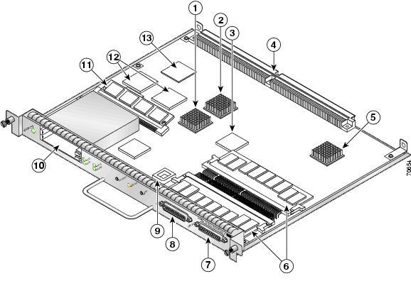
The RSP8, shown in Figure 1-22, is the main system processor for the Cisco 7507-MX and Cisco 7513-MX routers. The RSP8 provides switched routing and high-speed switching functions.
You install the RSP8 in slot 2 or slot 3 in the Cisco 7507-MX (see Figure 1-8) or in slot 6 or slot 7 in the Cisco 7513-MX (see Figure 1-14). The RSP8 is also compatible with the Cisco 7505, where it is installed in slot 4 (see Figure 1-2), the Cisco 7507, where it is installed in slot 2 or slot 3 (see Figure 1-5), the Cisco 7513, where it is installed in slot 6 or slot 7 (see Figure 1-11), and the Cisco 7576 where it is installed in slot 6 or slot 7 (see Figure 1-17).
Figure 1-22 Route Switch Processor (RSP8)
The RSP8 contains the system CPU, the system software (on a Flash Disk), the system memory components, and two PC Card slots, and it maintains and executes the management functions that control the system.
Although no monitoring of ±12V or temperature is done by the RSP8, a comparator device ensures that ±12V is maintained within the normal operating ranges, and three temperature sensors on the RSP8 send temperature information to the chassis interface (CI) card. The CI card reports all voltage and temperature readings, and these readings are available through standard software commands for environmental monitoring. The RSP8 uses a software-controlled configuration register, so you do not have to remove the RSP8 to configure jumpers. There are no user-configurable jumpers on the RSP8.
The RSP8 contains the following components:
•
•
•
•
•
In addition to running the system software from DRAM, the RSP8 contains and executes the following management functions that control the system:
•
•
•
•
The high-speed switching section of the RSP8 communicates with and controls the interface processors on the high-speed CyBus. This switching section of the RSP8 decides the destination of a packet and switches it based on that decision.
The RSP8 combines all of the switched routing and high-speed switching functions. The RSP8 supports the HSA feature, which allows two RSP8s to be used in a Cisco 7507, Cisco 7507-MX, Cisco 7513, or Cisco 7513-MX router. By default, the system master is the RSP8 that occupies the first RSP slot in the router: slot 2 in the Cisco 7507 and Cisco 7507-MX, and slot 6 in the Cisco 7513 and Cisco 7513-MX.
Note
The RSP8 is available as follows:
•
•
–
–
–
–
The RSP8 contains most of the memory components used by the system. Table 1-9 lists the functions of each type of memory on the RSP8.
Table 1-9 RSP8 Memory Components
DRAM
64-MB1 to 256-MB DIMMs
1 or 2
Any combination of 32-MB, 64-MB, or 128-MB DIMMs (based on DRAM required) for main Cisco IOS image functions
U12 or U12 and U152
SRAM3
8 MB (fixed)
-
SRAM for packet buffering functions (MEMD)
-
2 MB (fixed)
-
SRAM for tertiary (L3) CPU cache memory functions
-
NVRAM
2 MB
1
Nonvolatile SRAM for the system configuration file4
-
Flash memory
16-MB SIMM
1
Contains the Cisco IOS images on the RSP8
U1
40-MB5 Flash Disk
Up to 2
Contains the Cisco IOS images on up to 2 Flash Disks 7
Slot 0 or slot 0 and slot 1
16-MB or 20-MB6 Flash memory card
Up to 2
Contains the Cisco IOS images on up to 2 Flash memory cards7
Slot 0 or slot 0 and slot 1
1 64 MB of DRAM is the default DRAM configuration for the RSP8. The board is preconfigured with either two 32-MB DIMMs or one 64-MB DIMM.
2 Note that the larger DRAM DIMM must be placed in the U12 socket.
3 SRAM is not user-configurable or field-upgradable.
4 A system configuration file in NVRAM allows the Cisco IOS software to control several system variables.
5 A 40-MB Flash Disk in slot 0 is the default shipping configuration for RSP8 products.
6 Optional Flash memory.
7 Type I, Type II, and Type III PC Cards can be used in PC Card slot 1, and Type I and Type II PC Cards can be used in slot 0.
Note
RSP16—Cisco 7507, Cisco 7507-MX, Cisco 7513, and Cisco 7513-MX
The RSP16 is the latest-generation, main system processor module for the Cisco 7500 series routers.
The RSP16 supports the high system availability (HSA) feature, which allows two RSP16s (or an RSP16 and an RSP8) to be used in a Cisco 7507, Cisco 7507-MX, Cisco 7513, or Cisco 7513-MX router. The redundancy increases system availability during planned and unplanned network outages..
The RSP16 also supports high availability (HA), a series of features that operates similarly to HSA, but which further minimizes system downtime. (HSA is the system default.)
The RSP16 is not available as an upgrade to an existing RSP, but supports the VIP2, VIP4, and new VIP6-80. The RSP16 does not support legacy interface processors, except for the CIP2, GEIP, GEIP+, FEIP2-DSW-2TX, FEIP2-DSW-2FX, SRPIP, CX-CIP2-ECA1 and ECA2. The RSP16 contains the central processing unit (CPU) and most of the memory components for the router. The Cisco IOS software images reside in Flash memory, located as follows on the RSP16:
•
•
Note
Storing the IOS software images in Flash memory enables you to download and boot from upgraded Cisco IOS software images remotely or from software images resident in the RSP16 Flash memory, without having to remove and replace read-only memory (ROM) devices.
Figure 1-23 Route Switch Processor (RSP16)
The RSP16 also contains:
•
•
In addition to running the system software from DRAM, the RSP16 contains and executes the following management functions that control the system:
•
•
•
•
The high-speed switching section of the RSP16 communicates with and controls the interface processors on the high-speed CyBus. This switching section of the RSP16 decides the destination of a packet and switches it based on that decision.
Note
Following are chassis slot requirements for ensuring RSP16 compatibility.
•
•
•
•
Table 1-10 RSP16 Memory Components
DRAM
128MB1 to 516MB DIMMs
1 or 2
128-, 256-, or 516-MB DIMM2 (based on DRAM required) for main Cisco IOS image functions
U130, or U130 and U180
SRAM3
8 MB (fixed)
-
SRAM for packet buffering functions (MEMD)
-
2MB (fixed)
-
SRAM for tertiary (L3) CPU cache memory functions
-
NVRAM
2MB
1
Nonvolatile SRAM for the system configuration file4
U5
Flash Memory
16MB SIMM5
1
Contains the Cisco IOS images on the RSP16
U1
48MB, 64MB6 , or 128MB Flash Disk
Up to 2
Contains the Cisco IOS images on up to two Flash Disks
Slot 0, or slot 0 and slot 1
Flash Boot ROM
512KB
1
Flash EPROM for the ROM monitor program image
U7
1 128MB DRAM is the default DRAM configuration for the RSP16.
2 Do not mix memory sizes. If installing 2 DIMMs, both DIMMs must be the same size. If your router includes redundant RSPs, the RSPs should have the same memory size.
3 SRAM is not user-configurable or field-upgradable.
4 A system configuration file is contained in NVRAM, which allows the Cisco IOS software to control several system variables.
5 This 16-MB SIMM Flash memory is not supported on the RSP2, RSP4/4+, or RSP8.
6 A 64-MB Flash Disk is the default shipping configuration for the RSP16 product.
Common RSP Hardware Features
This section discusses hardware features common to all RSPs. (For convenience, the RSP2, RSP4/4+, RSP8, and RSP16 are referred to as the RSP with differences clearly noted.)
RSP LEDs
Several LEDs on the RSP indicate system and RSP status, as follows:
•
•
The RSP controls the normal and CPU halt LEDs and turns them on in parallel to indicate that the system is operational.
•
•
Note
RSP DRAM
Dynamic random-access memory (DRAM) stores routing tables, protocols, and network accounting applications. Table 1-11 lists the RSP DRAM configurations.
Caution
RSP SRAM
RSP static random-access memory (SRAM) provides packet buffering and CPU cache memory functions. Table 1-12 lists the RSP SRAM configurations.
Table 1-12 RSP SRAM Configurations
RSP2
1 MB of SRAM for packet buffering, and 512 KB of secondary CPU cache SRAM
RSP4/4+
2 MB of SRAM for packet buffering, and 512 KB of secondary CPU cache SRAM
RSP8
8 MB of SRAM for packet buffering functions (MEMD)
1 RSP SRAM is not field-replaceable.
RSP NVRAM
RSP nonvolatile random-access memory (NVRAM) stores the system configuration and the environmental monitoring logs. It is backed up with built-in lithium batteries that retain the contents for a minimum of 5 years.
Note
RSP Flash Memory
Flash memory, either on a SIMM or on a Flash memory PC Card or Flash Disk, allows you to remotely load and store multiple Cisco IOS software and microcode images and to back up configurations on your Cisco 7500 series router.
You can download a new image over the network or from a local server and then add the new image to Flash memory or replace the existing files. You can then boot the routers either manually or automatically from any of the stored images. Flash memory also functions as a TFTP server to allow other servers to remotely boot from stored images or to copy them into their own Flash memory.
Note
RSP EEPROM
An electrically erasable programmable read-only memory (EEPROM) component on the RSP stores board-specific information such as the board serial number, part number, controller type, hardware revision, and other details unique to each board. This EEPROM is not a spare and cannot be programmed in the field.
RSP Asynchronous Serial Ports—Console and Auxiliary
Two asynchronous EIA/TIA-232 serial ports on the RSP, the console and auxiliary ports, provide the means for connecting a terminal, modem, CSU, DSU, or other external device for configuring, managing, or connecting to the system. A data circuit-terminating equipment (DCE) EIA/TIA-232 receptacle console port on the RSP provides a direct connection for a console terminal.
Note
The adjacent DTE EIA/TIA-232 plug auxiliary port supports flow control and is often used to connect a modem, a DSU/CSU, or other optional equipment for Telnet management of the attached device.
The console and auxiliary ports support asynchronous transmission. Asynchronous transmission uses control bits to indicate the beginning and end of characters, rather than precise timing. Serial interface ports on serial interface processors and port adapters support synchronous transmission, which maintains precise clocking between the transmitter and receiver by sending frames of information that consist of separate clock signals along with the data signals.
Note
The following sections describe the pinouts for the console and auxiliary connectors and cables for the RSPs:
•
•
•
(Specific differences between RSPs are clearly noted.)
Note
RSP Console Port Pinout
The console port on the RSP is an EIA/TIA-232 DCE DB-25 receptacle. Both the
Data Set Ready (DSR) and Data Carrier Detect (DCD) signals are active when the system is running. The console port does not support hardware flow or modem control. The console port requires a straight-through EIA/TIA-232 cable. Table 1-13 lists the console port pinout.
RSP Auxiliary Port Pinout
The auxiliary port on the RSP is an EIA/TIA-232 DTE DB-25 plug to which you can attach external equipment in order to access the router from the network. The Request To Send (RTS) signal tracks the state of the Clear To Send (CTS) input. The auxiliary port supports hardware flow control and modem control. Table 1-14 lists the auxiliary port pinout.
RSP2, RSP4/4+, and RSP8 Console and Auxiliary Y-Cable Pinouts
The console and auxiliary Y-cables allow you to simultaneously connect the console or auxiliary ports on two RSP2s, two RSP4/4+s, two RSP8s or one of each, to one console terminal or external auxiliary device (such as a modem, and so forth). These are configured as system master and slave in RSP slots 2 and 3 in the Cisco 7507 and Cisco 7507-MX, and RSP slots 6 and 7 in the Cisco 7513 and Cisco 7513-MX.
Note
The two Y-cables ship with the Cisco 7507, Cisco 7507-MX, Cisco 7513, and Cisco 7513-MX chassis as Product Numbers CAB-RSP2CON and CAB-RSP2AUX, and are available as spare parts (=).
Table 1-15 lists the console Y-cable pinout, and Table 1-16 lists the auxiliary Y-cable pinout.
AC-Input and DC-Input Power Supply Overview
The Cisco 7500 series routers support AC-input and DC-input power supplies. The Cisco 7505 uses one AC-input or DC-input power supply, whereas the Cisco 7507, Cisco 7507-MX, Cisco 7513, Cisco 7513-MX, and Cisco 7576 support dual AC-input or DC-input power supplies. Power specifications are listed in Table 1-1 (Cisco 7505), Table 1-2 (Cisco 7507), Table 1-3 (Cisco 7507-MX), Table 1-4 (Cisco 7513), Table 1-5 (Cisco 7513-MX), and Table 1-6 (Cisco 7576).
Caution
The DC-input power cable is not available from Cisco Systems; however, it is available from commercial cable vendors. DC-input power cable specifications are listed in Table 1-1 (Cisco 7505), Table 1-2 (Cisco 7507), Table 1-3 (Cisco 7507-MX), Table 1-4 (Cisco 7513), Table 1-5 (Cisco 7513-MX), and Table 1-6 (Cisco 7576).
For Cisco 7500 series routers used in North America, the following AC-input and DC-input power supplies are available:
•
•
•
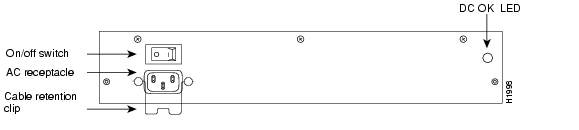
Figure 1-24 AC-Input Power Supply (Cisco 7505)
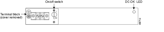
Figure 1-25 DC-Input Power Supply (Cisco 7505)
Figure 1-26 AC-Input Power Supply (Cisco 7507 and Cisco 7507-MX)
Figure 1-27 DC-Input Power Supply (Cisco 7507 and Cisco 7507-MX)
Figure 1-28 AC-Input Power Supply (Cisco 7513, Cisco 7513-MX, and Cisco 7576)
Figure 1-29 DC-Input Power Supply (Cisco 7513, Cisco 7513-MX, and Cisco 7576)
For Cisco 7500 series routers used in the United Kingdom (U), Australia (A), Italy (I), and the continental European (E) countries (excluding Italy), the following power supplies are available:
•
–
–
•
–
–
•
–
–
•
–
–
The AC-input and DC-input power supplies available for countries outside North America differ from the North American power supplies in the following ways: the operating (input) voltages of each power supply and the AC-input power cables that ship with the power supplies are specific to each country.
For power supply maintenance information, see the following sections as appropriate for your Cisco 7500 series router:
•
•
•
Arbiter Overview
In the Cisco 7500 series routers, an internal printed circuit board called the arbiter arbitrates traffic on the CyBus and generates the CyBus clock.
The Cisco 7505 has a single arbiter, whereas the Cisco 7507 and Cisco 7513 have a dual arbiter for the dual CyBuses. The Cisco 7576 includes two dual arbiters, one for router A and one for router B. The arbiter is attached directly to the front (noninterface processor side) of the system backplane. It controls traffic across each CyBus by prioritizing access requests from interface processors to ensure that each request is processed and to prevent any interface processor from jeopardizing each CyBus and interfering with the ability of the other interface processors to access the RSP.
The arbiter provides the following services for the system:
•
•
•
Note
Turbo Arbiter in Cisco 7500 Series Routers publication for details on how to identify whether or not your Cisco 7507 or Cisco 7513 includes a turbo arbiter.
Chassis Interface Overview
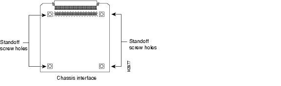
The Cisco 7500 series routers have an internal printed board called the chassis interface (CI) that provides the environmental and power supply monitoring functions for the router. (See Figure 1-30.)
Note
Figure 1-30 7500 Series Chassis Interface
The CI isolates the CPU and system software from chassis-specific variations, and is attached directly to the front (noninterface processor side) of the system backplane.
The functions of the CI are as follows:
•
•
•
•
Note
This achieves a hard shutdown of one router without affecting the other router. The RSP and interface processors will remain disabled until the power is manually recycled. This allows you to choose a suitable time to recycle the power when it will not adversely affect your users.For CI maintenance information, see "Removing and Replacing the Chassis Interface in the Cisco 7505" section, "Removing and Replacing the Chassis Interface in the Cisco 7507 and Cisco 7507-MX" section, and "Removing and Replacing the Chassis Interface in the Cisco 7513, Cisco 7513-MX, and Cisco 7576" section on page 7-14. (For all Cisco 7500 series routers, a spare CI ships as Product Number MAS-7500CI=.)
Fan Tray and Blower Assembly Overview
Blower and fan tray assemblies cool the interior of the Cisco 7505 router chassis. It may be difficult to determine whether or not the fans or blowers are operating in noisy, air-conditioned rooms. If you determine that they are not operating, contact a customer service representative immediately. There are no installation adjustments that you should make if the fan or blower assembly does not function properly at initial startup.
Cisco 7505 Fan Tray Assembly
The Cisco 7505 uses a fan tray assembly (see Figure 1-31) consisting of six fans that supply cooling air to the chassis interior. The assembly is accessible from behind the chassis front panel.
Figure 1-31 Fan Tray Assembly (Cisco 7505)
All six fans should be operating whenever system power is on. The system automatically shuts down if any one or more of the fans is operating outside the specified range. A variable speed feature allows the fans to operate at a slower speed when the internal chassis temperature is within the normal operating range, and at a higher speed if the internal temperature exceeds a specified temperature. (A spare fan tray ships as Product Number MAS/5-FAN=.) For fan tray maintenance information, see the "Removing and Replacing the Cisco 7505 Fan Tray" section.
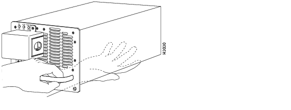
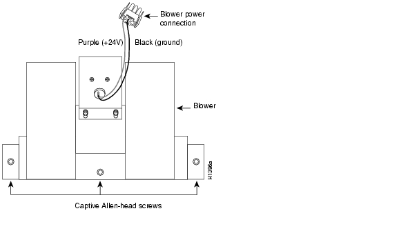
Cisco 7507 and Cisco 7507-MX Blower Assembly
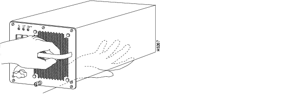
The Cisco 7507 and Cisco 7507-MX uses a blower assembly (see Figure 1-32) that supplies cooling air to the chassis interior. (A spare blower assembly ships as Product Number MAS-7KFAN=.) For blower assembly maintenance information, see the "Removing and Replacing the Cisco 7507 and Cisco 7507-MX Blower Assembly" section.
Figure 1-32 Blower Assembly (Cisco 7507 and Cisco 7507-MX)
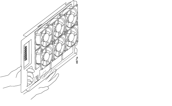
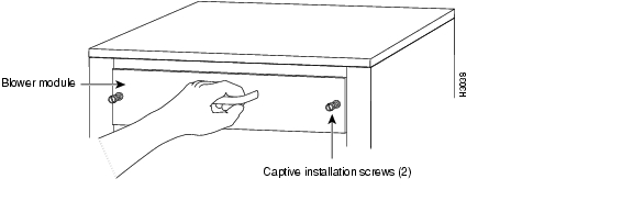
Cisco 7513, Cisco 7513-MX, and Cisco 7576 Blower Module Assembly
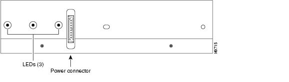
The Cisco 7513, Cisco 7513-MX, and Cisco 7576 use a blower module assembly that is located at the top rear-end of the chassis (see Figure 1-33 and Figure 1-34). The assembly supplies cooling air to the chassis interior. The blower module assembly also contains the system LEDs, which are located on a nonremovable printed circuit card at the rear of the interior of the blower module assembly. (A spare blower module assembly ships as Product Numbers MAS-7513-FAN= for the Cisco 7513 and Cisco 7513-MX and MAS-7576-FAN= for the Cisco 7576.) For blower module assembly maintenance information, see the "Removing and Replacing the Cisco 7513, Cisco 7513-MX, and Cisco 7576 Blower Module" section on page 7-10.
Figure 1-33 Blower Module Assembly (Partial Rear View of Cisco 7513, Cisco 7513-MX, and Cisco 7576)
Figure 1-34 Blower Module Assembly (Rear View)
Interface Processor Overview
Interface processors for the Cisco 7500 series routers are separate processor modules that are installed in the routers' interface processor slots and attach to the system backplane.
Note
Each interface processor comprises a modular, self-contained interface (printed circuit) board and one or more network interface connectors in a single 11 x 14-inch unit. You can install and remove interface processors without opening the chassis (known as online insertion and removal, or OIR) and without turning off the chassis power.
The microcode on each interface processor contains board-specific software instructions. New features and enhancements to the system or interfaces are often implemented in microcode upgrades.
Each interface processor (and the Cisco 7500 series router in which it is installed) supports downloadable microcode, which enables you to download new microcode images remotely and store them in Flash memory. You can then use software commands to load a specific microcode image from Flash memory.
Each interface processor has a unique bank of status LEDs, and all have a common LED (called the enabled LED) on the interface processor's faceplate. The enabled LED lights when the interface processor has completed its initialization, indicating that as a minimum, the interface processor is correctly connected to the backplane, that it is receiving power, and that it contains a valid microcode version. If any of these conditions is not met, or if the initialization fails for other reasons, the enabled LED does not light. Additional LEDs on each interface processor type indicate the state of the interfaces.
The following interface processors are available for the Cisco 7500 series routers:
•
•
•
•
•
•
•
•
•
•
•
•
•
–
–
–
–
–
–
–
–
–
–
–
–
–
–
–
–
–
–
Note
System Software Overview
In Cisco 7500 series routers, Flash memory on the RSP contains the default system software. An EPROM device on each interface processor contains the latest interface processor microcode version, in compressed form. At system startup, an internal system utility scans for compatibility problems between the installed interface processor types and the bundled microcode images, then decompresses the images into running memory (DRAM). The bundled microcode images then function the same as images loaded from the microcode EPROM.
The Cisco 7500 series routers support downloadable Cisco IOS software and interface processor microcode images, which enables you to remotely download, store, and boot from a new image. The Cisco IOS image runs from the DRAM on the RSP; interface processor microcode images run from the DRAM on the specific interface processor.
The publication Upgrading Software and Microcode in the Cisco 7000 Series Routers which is available online, on the Documentation CD-ROM, or as a printed copy, provides instructions for upgrading from a TFTP server, floppy disk, or Flash memory card.
![]()
![]()
![]()
![]()
![]()
![]()
![]()
![]()
Posted: Thu Mar 24 11:25:34 PST 2005
All contents are Copyright © 1992--2005 Cisco Systems, Inc. All rights reserved.
Important Notices and Privacy Statement.