|
|

Table Of Contents
Preventing Electrostatic Discharge Damage
AC-Input and DC-Input Power Guidelines
Cisco 7505 Power Considerations
Cisco 7507 and Cisco 7507-MX Power Considerations
Cisco 7513, Cisco 7513-MX, and Cisco 7576 Power Considerations
Interference Considerations with Cabling
Distance Limitations of Interface Cabling
Site Environment, Chassis Temperature, and Airflow Guidelines
Cisco 7505 Airflow Considerations
Cisco 7507 and Cisco 7507-MX Airflow Considerations
Cisco 7513, Cisco 7513-MX, and Cisco 7576 Airflow Considerations
Equipment Rack-Mounting Guidelines
General Equipment Rack Ventilation Considerations
Cisco 7505 Rack-Mount Considerations
Cisco 7507 and Cisco 7507-MX Rack-Mount Considerations
Cisco 7513, Cisco 7513-MX, and Cisco 7576 Rack-Mount Considerations
Environmental Monitoring and Reporting Overview for the Cisco 7500 Series
Cisco 7500 Series Environmental Monitoring
Cisco 7500 Series Temperature and Voltage Thresholds
Cisco 7500 Series Environmental Reports
Preparing for Installation
This chapter includes specific information about required tools and parts, safety guidelines, and preparatory information required to ensure a successful installation of your Cisco 7500 series router.
Do not unpack the Cisco 7500 series router until you are ready to install it. Keep the chassis in the shipping container to prevent accidental damage until you have determined where you want it installed. Use the appropriate unpacking documentation included with your Cisco 7500 series router.
The Cisco Information Packet provides safety, and service, and support information, and is included in the shipping container, together with any companion publications you specified on your order. Inspect all items for shipping damage. If anything is damaged, immediately contact a customer service representative.
Sections in this chapter include the following:
•
AC-Input and DC-Input Power Guidelines
•
•
•
Tools and Parts You Need
Following are the tools and parts generally required to install your Cisco 7500 series router:
•
•
If you are installing the Cisco 7500 series router in a rack, you might also need the following tools:
–
–
–
–
Note
•
•
Cisco 7576 (required)•
•
•
•
•
Safety Recommendations
Warning
Observe the following safety guidelines before installing a Cisco 7500 series router; they will help to ensure your safety and protect your equipment. This list is not inclusive of all potentially hazardous situations, so be alert.
•
•
•
•
Warning
Safety with Electricity
Follow these basic guidelines when working with any electrical equipment:
•
•
–
–
–
•
•
•
Warning
Warning
Warning
•
•
•
•
In addition, use the guidelines that follow when working with any equipment that is disconnected from a power source, but still connected to telephone or network wiring:
•
•
•
•
•
•
Warning
Chassis Lifting Guidelines
The Cisco 7500 series chassis are not intended to be moved frequently. Before you install the router, ensure that your site is properly prepared so you can avoid having to move the chassis later to accommodate power sources and network connections.
In general, two people are required to lift a Cisco 7507, Cisco 7507-MX, Cisco 7513, Cisco 7513-MX, or Cisco 7576 chassis. (See Figure 2-1.) Grasp the chassis underneath the lower edge and lift with both hands. To prevent injury, keep your back straight and lift with your legs, not your back.
Caution
Figure 2-1 Lifting Safely (Cisco 7507 Shown)
In general, whenever you lift a Cisco 7500 series chassis, follow these guidelines:
•
•
•
•
•
•
•
Caution
Warning
Note
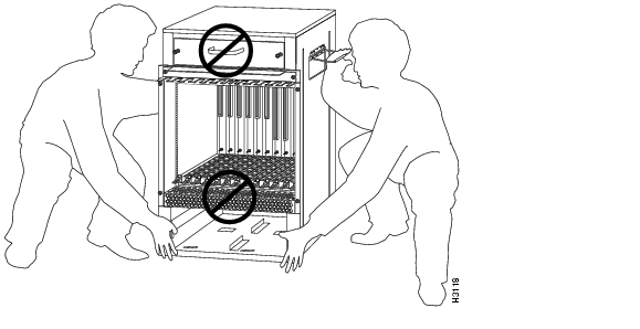
When you get ready to place the Cisco 7513, Cisco 7513-MX, or Cisco 7576 into a rack or onto a tabletop, each person should lift it by grasping the side handle with one hand and the bottom of the chassis with the other, and lift the chassis with your legs, as shown in Figure 2-2 . (Do not lift the chassis using the blower module handle or the air intake vent below the card cage.)
Figure 2-2 Correct Way to Lift the Cisco 7513, Cisco 7513-MX, or Cisco 7576
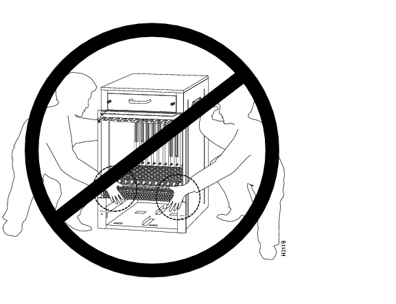
Caution
Figure 2-3 Incorrect Way to Lift the Cisco 7513, Cisco 7513-MX, or Cisco 7576
Preventing Electrostatic Discharge Damage
Electrostatic discharge (ESD) can damage equipment and impair electrical circuitry. It occurs when electronic components are improperly handled and can result in intermittent or complete failures. Always ensure that the chassis is electrically connected to earth ground. Wear an ESD-preventive wrist strap, ensuring that it makes good skin contact. To safely channel unwanted ESD voltages to ground, connect the clip to an unpainted surface of the chassis frame. If no wrist strap is available, ground yourself to the metal chassis.
Caution
AC-Input and DC-Input Power Guidelines
The wide-input AC-input power supplies in the Cisco 7500 series routers use a power factor corrector (PFC) that allows the router to operate on input voltage and current within the AC-voltage range of 100 to 240 VAC and 50 to 60 Hz.
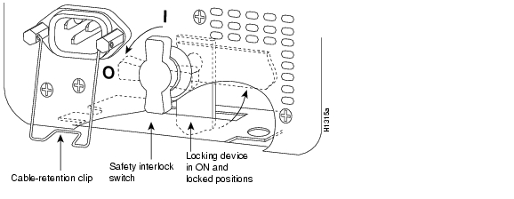
In Chapter 1, Table 1-1 (for the Cisco 7505), Table 1-2 (for the Cisco 7507), Table 1-3 (for the Cisco 7507-MX), Table 1-4 (for the Cisco 7513), Table 1-5 (for the Cisco 7513-MX), and Table 1-6 (for the Cisco 7576) list system power specifications, including input voltage and operating frequency ranges. The power supplies in the Cisco 7507, Cisco 7507-MX, Cisco 7513, Cisco 7513-MX, and Cisco 7576 routers have two safety interlock features as shown in Figure 2-4 . A locking device on each power supply prevents the power supply from being removed from the chassis when the power supply switch is on. When the switch is in the on (|) position, a metal locking device extends into a slot in the chassis. When the switch is in the off (O) position, the locking device is raised and clears the slot. Also, a retention clip prevents the AC-input power supply power cable from being accidentally pulled out of the power supply socket.
For additional power supply information, see the "AC-Input and DC-Input Power Guidelines" section. Check the power at your site before installation and periodically after installation to ensure that you are receiving clean power; install a power conditioner if necessary. We recommend that you install a power conditioner between the AC power source and the router to help avoid problems caused by power spikes and brownouts, and to help protect against equipment damage from lightning strikes. We also recommend an uninterruptible power source (UPS) for the router to protect against power failures at your site.
Warning
Figure 2-4 Power Supply Safety Interlocks (Cisco 7507 AC-Input Power Supply Shown)
Cisco 7505 Power Considerations
The single 600W wide-input AC-input power supply for the Cisco 7505 router uses a power factor corrector (PFC) that allows the Cisco 7505 to operate on input voltage and current within the range of 100 to 240 VAC and 50 to 60 Hz.
The 600W DC-input power supply allows the Cisco 7505 to operate between -40 and -52 VDC in North America (-48 VDC nominal) and between -56 and -72 VDC in the European Union (-60 VDC nominal). We recommend that you use an 8-AWG, highly flexible stranded cable for the DC power connections. (See Table 1-1 for a list of Cisco 7505 power specifications.)
Note
Cisco 7507 and Cisco 7507-MX Power Considerations
The 700W AC-input power supply for the Cisco 7507 and Cisco 7507-MX routers uses a power factor corrector (PFC) that allows it to operate on input voltage and current within the range of 100 through 240 VAC and 47 through 63 Hz. The 700W DC-input power supply allows the Cisco 7507 and Cisco 7507-MX to operate between -40 and -72 VDC (-48 VDC nominal). We recommend that you use an 8-AWG, highly flexible stranded cable for the DC power connections. (See Table 1-2 and Table 1-3for a list of Cisco 7507 and Cisco 7507-MX power specifications.)
Note
A second, identical power supply is also present in routers configured with the redundant power option; this ensures that power to the chassis continues uninterrupted if one power supply fails. It also provides uninterrupted power if the input power line fails, but only if the power supplies are connected to separate input lines.
Whenever possible, provide redundant power sources for each power supply installed in the chassis. For AC-input installations, install an uninterruptible power source where possible. Install proper grounding to avoid damage from lightning and power surges.
If only one input line is available, and you must connect both power supplies to the same source, the redundant power supply will provide continuous power if the first power supply fails. It cannot provide power backup if the input power fails.
Warning
Cisco 7513, Cisco 7513-MX, and Cisco 7576 Power Considerations
The 1200W AC-input power supply in the Cisco 7513, Cisco 7513-MX, and Cisco 7576 routers uses a power factor corrector (PFC) that allows it to operate on input voltage and current within the range of 100 through 240 VAC and 47 through 63 Hz. Follow these precautions and recommendations when planning power connections to the router. (See Table 1-4 for a list of Cisco 7513 power specifications, Table 1-5 for a list of Cisco 7513-MX power specifications, and Table 1-6 for a list of Cisco 7576
power specifications.)
Note
Cisco 7513-MX, and Cisco 7576 chassis employ two threaded M5 chassis grounding receptacles. These receptacles are intended to be bonded directly to the central office or other interior ground system and are located on the rear of the chassis. The chassis grounding receptacles require M5 screws and locking hardware, which are not included.A second, identical power supply is also present in routers configured with the redundant power option; this ensures that power to the chassis continues uninterrupted if that one power supply fails. It also provides uninterrupted power if the input power line fails, but only if the power supplies are connected to separate input lines.
Whenever possible, provide redundant power sources for each power supply installed in the chassis. For AC-input installations, install an uninterruptible power source where possible. Install proper grounding to avoid damage from lightning and power surges.
If only one input line is available, and you must connect both power supplies to the same source, the redundant power supply will provide continuous power if the first power supply fails. It cannot provide power backup if the input power fails.
Warning
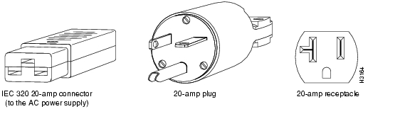
An AC-input-powered Cisco 7513, Cisco 7513-MX, or Cisco 7576 operating at 120 VAC requires a minimum of 20A service, with a 20A receptacle at the power source. The power cable supplied with the chassis uses a 20A plug. Figure 2-5 shows cable features required to connect the 20A plug to your AC source.
Figure 2-5 20A AC-Input Power Cable Connector, Plug, and Receptacle (Cisco 7513,
Cisco 7513-MX, and Cisco 7576)
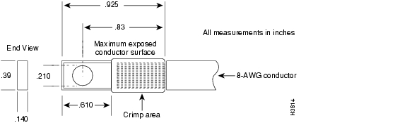
The DC-powered chassis requires a minimum 35A dedicated service (at -48 VDC). We recommend that you use an 8-AWG, highly flexible stranded cable for the DC power connections. Figure 2-6 shows the conductor preparations.
Figure 2-6 DC-Input Power Cable Connection to Terminal Block (Cisco 7513, Cisco 7513-MX, and Cisco 7576)
Plant Wiring Guidelines
This section provides guidelines for setting up the plant wiring and cabling at your site. When planning the location of the new system, consider wiring issues, distance limitations for signaling, electromagnetic interference, and connector compatibility, as described in the sections that follow.
Interference Considerations with Cabling
When wires are run for any significant distance in an electromagnetic field, interference can occur between the field and the signals on the wires. This fact has two implications for the construction of plant wiring:
•
•
Note
If you use twisted-pair cable in your plant wiring with a good distribution of grounding conductors, the plant wiring is unlikely to emit radio interference. When exceeding the recommended distances, use a high-quality twisted-pair cable with one ground conductor for each data signal.
If wires exceed recommended distances, or if wires pass between buildings, give special consideration to the effect of a lightning strike in your vicinity. The electromagnetic pulse (EMP) caused by lightning or other high-energy phenomena can easily couple enough energy into unshielded conductors to destroy electronic devices. If you have had problems of this sort in the past, you might want to consult experts in electrical surge suppression and shielding.
Most data centers cannot resolve the infrequent but potentially catastrophic problems just described without pulse meters and other special equipment. These problems can cost a great deal of time to identify and resolve, so take precautions by providing a properly grounded and shielded environment, with special attention to issues of electrical surge suppression.
Warning
Warning
Warning
Distance Limitations of Interface Cabling
The length of your networks and the distance between connections depend on the type of signal, the signal speed, and the transmission media (the type of cabling used to transmit the signals). For example, standard coaxial cable has a greater channel capacity than twisted-pair cabling.
The distance and rate limits for the available electrical interfaces supported by Cisco 7500 series routers are recommended maximum speeds and distances for signaling. If you understand the electrical problems that might arise and can compensate for them, you might get good results with faster rates and greater distances; however, do so at your own risk.
Note
For complete information on recommended maximum speeds and distances for signaling and interface specifications for the electrical interfaces supported by the Cisco 7500 series routers, refer to the companion publication Interface Processor Installation and Configuration Guide.
Site Environment, Chassis Temperature, and Airflow Guidelines
Cisco 7500 series routers can operate as standalone systems placed on a table or as rack-mounted systems in a data processing or lab environment. (We recommend rack-mounting for all Cisco 7500 series routers.)
The internal fan or blower operates so that it maintains an acceptable operating temperature inside the chassis. The router requires a dry, clean, well-ventilated, and air-conditioned environment. The internal blower pulls ambient air through the chassis to cool the internal components. To allow sufficient airflow, maintain a minimum of 2 inches (5.08 cm) of clearance at both the inlet and exhaust openings on the chassis. If the airflow is blocked or restricted, or if the inlet air is too warm, an overtemperature condition can occur. Under extreme conditions, the environmental monitoring system will shut down the power to protect the system components.
To help maintain normal operation and avoid unnecessary maintenance, plan your site configuration and prepare your site before installation. After installation, make sure that the site maintains an ambient temperature of 32 through 104°F (0 through 40°C), and keep the area around the chassis as free from dust as is practical. For a description of the environmental monitor and status levels, see the "Environmental Monitoring and Reporting Overview for the Cisco 7500 Series" section.
If the temperature of the air drawn into the chassis is higher than desirable, the air temperature inside the chassis might also be too high. This condition can occur when the wiring closet or rack in which the chassis is mounted is not ventilated properly, when the exhaust of one device is placed so it enters the air inlet vent of the chassis, or when the chassis is the top unit in an unventilated rack. Any of these conditions can inhibit airflow and create an overtemperature condition.
Because the inlet air flows into one part of the chassis and out another, other devices can be rack-mounted with as little as 1 inch (2.54 cm) of clearance above and below the chassis. However, when mounting a router in a rack with other equipment, or when placing it on a table with other equipment located close by, ensure that the exhaust from other equipment does not blow into the inlet of the chassis. The inlet air is drawn in and exhausted as shown in Figure 2-7 (for the Cisco 7505), Figure 2-8 (for the Cisco 7507 and Cisco 7507-MX), and Figure 2-9 (for the Cisco 7513, Cisco 7513-MX, and Cisco 7576).
Table 2-1 lists the operating and nonoperating environmental site requirements. To maintain normal operation and ensure high system availability, maintain an ambient temperature and clean power at your site.
The ranges in Table 2-1 are those within which the router will continue to operate; however, a measurement that is approaching the minimum or maximum of a range indicates a potential problem. You can maintain normal operation by anticipating and correcting environmental anomalies before they approach the maximum operating range.
Table 2-1 Environmental Specifications for the Cisco 7500 Series Routers
Temperature, ambient operating
32°F (0°C)
104°F (40°C)
Temperature, ambient nonoperating and storage
-4°F (-20°C)
149°F (65°C)
Humidity, ambient (noncondensing) operating
10%
90%
Humidity, ambient (noncondensing) nonoperating and storage
5%
95%
Altitude, operating and nonoperating
Sea level
10,000 ft (3050 m)
Vibration, operating
5 to 200 Hz, 0.5 g1 (1 octave per minute)
-
Vibration, nonoperating
5 to 200 Hz, 1 g (1 octave per minute)
200 to 500 Hz, 2 g (1 octave per minute) -
1 g = force of gravity; 32 ft/sec2.
Cisco 7505 Airflow Considerations
In the Cisco 7505, six individual axial fans draw cooling air through the chassis interior to maintain an acceptable temperature for the internal components. The fans draw air in through the inlet vents on the side of the chassis opposite the fans, across the processor modules and other internal components, and through the exhaust vents adjacent to the fans.
The sides of the chassis must remain unobstructed to ensure adequate airflow and prevent overheating inside the chassis. A temperature sensor on the RSP monitors the internal air temperature. The power supply has two fans for cooling.
Figure 2-7 shows the chassis fans and airflow through the Cisco 7505.
Figure 2-7 Airflow Through the Cisco 7505
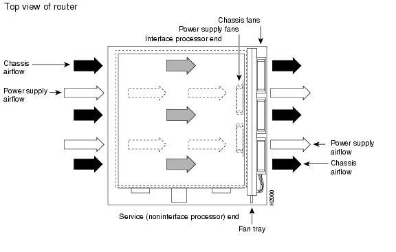
Cisco 7507 and Cisco 7507-MX Airflow Considerations
The system blower on the Cisco 7507 and Cisco 7507-MX provides cooling air for the processor modules. The blower draws air in through the air filter in the front chassis panel and directs it up through the floor of the internal slot compartment and over the cards. The exhaust air is forced out the rear of the chassis above and to each side of the processor slots. The blower needs a clean air filter in order to draw in sufficient amounts of cooling air; excessive dust in the filter will restrict the airflow. Keep the air filter clean and replace it when necessary.
Figure 2-8 shows the system blower and airflow through the Cisco 7507 and Cisco 7507-MX.
Figure 2-8 Airflow Through the Cisco 7507 and Cisco 7507-MX
Sensors on the RSP2 (for example) monitor the inlet and internal chassis air temperatures. If the air temperature at either of the sensors exceeds a desired threshold, an environmental monitor displays warning messages and can interrupt system operation to protect the system components from possible damage from excessive heat or electrical current.
The power supplies have their own fans. An air dam between the power supply bays and the processor module compartment keeps the airflow constant.
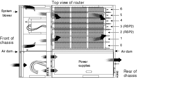
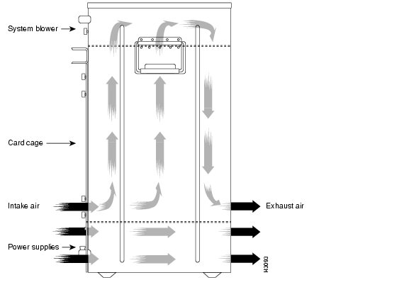
Cisco 7513, Cisco 7513-MX, and Cisco 7576 Airflow Considerations
The blower on the Cisco 7513, Cisco 7513-MX, and Cisco 7576 provides cooling air for the processor modules. The exhaust air is forced out the front of the chassis behind the card cage.
Figure 2-9 shows the system blower and airflow through the Cisco 7513, Cisco 7513-MX, and Cisco 7576.
Figure 2-9 Airflow Through the Cisco 7513, Cisco 7513-MX, and Cisco 7576
The power supplies have their own fans with airflow that is independent of the chassis airflow. Ensure that there is minimum front and back clearance of 6 inches (15.24 cm).
Equipment Rack-Mounting Guidelines
This section provides the equipment rack-mounting guidelines that must be observed before installing a Cisco 7500 series router in an equipment rack.
General Equipment Rack Ventilation Considerations
If you plan to install the router in an equipment rack, you can avoid overtemperature conditions by observing the following precautions:
•
•
•
•
•
In addition, the following sections contain specific rack-mounting guidelines for the Cisco 7500 series routers:
•
•
•
Cisco 7505 Rack-Mount Considerations
The rack-mounting hardware included with the Cisco 7505 is suitable for most 19-inch (48.26-cm) equipment racks or 2-post racks. The router chassis mounts to two posts or rails in the rack with two mounting ears, which attach to the sides of the chassis. Ideally, you should be able to access both the interface processor and noninterface processor ends of the router without having to remove it from the rack. Before using a particular rack, check for obstructions (such as a power strip) that could impair access to the interface processors or chassis cover panel.
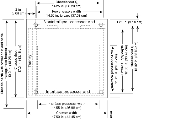
As an alternative, the router can be mounted on an equipment shelf provided that the rack dimensions allow the router to be secured to the shelf, and the overall configuration permits safe installation and access. Figure 2-10 shows the chassis footprint and outer dimensions.
To use the rack-mounting hardware provided with the router, consider the following guidelines:
•
•
•
•
Figure 2-10 Chassis Footprint and Outer Dimensions (Cisco 7505)
Caution
When planning your Cisco 7505 rack installation, consider the following guidelines:
•
•
•
•
•
•
•
In addition to the preceding guidelines, we recommend you review the precautions for avoiding overtemperature conditions in the "General Equipment Rack Ventilation Considerations" section.
Cisco 7507 and Cisco 7507-MX Rack-Mount Considerations
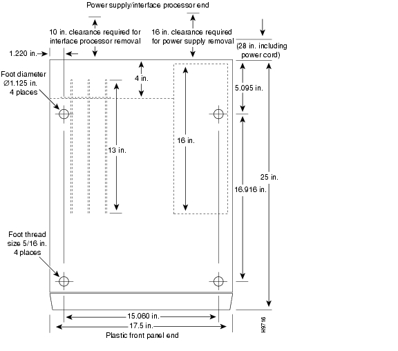
An optional rack-mounting kit is available for mounting the Cisco 7507 or Cisco 7507-MX in a standard 19-inch (48.26 cm) equipment rack. The mounting kit is not suitable for use with 2-post equipment racks, or those with obstructions (such as a power strip) that could impair access to the interface processors and power supplies. In telco environments or at installation sites that use nonstandard racks, the router can be mounted on an equipment shelf, provided that the rack dimensions allow safe installation and access to the power supplies and interface processors. Figure 2-11 shows the chassis footprint and outer dimensions.
To use the optional rack-mount kit, your equipment rack must meet the following requirements:
•
•
•
•
Figure 2-11 Chassis Footprint and Outer Dimensions (Cisco 7507 and Cisco 7507-MX)
Caution
When planning your Cisco 7507 or Cisco 7507-MX rack installation, consider the following guidelines:
•
•
•
•
•
•
•
In addition to the preceding guidelines, we recommend you review the precautions for avoiding overtemperature conditions in the "General Equipment Rack Ventilation Considerations" section.
Cisco 7513, Cisco 7513-MX, and Cisco 7576 Rack-Mount Considerations
The rack-mounting hardware included with the Cisco 7513, Cisco 7513-MX, and Cisco 7576 is suitable for most 19-inch equipment racks and 2-post racks. Ideally, you should be able to access both the interface processor and noninterface processor ends of the router without having to remove the chassis from the rack.
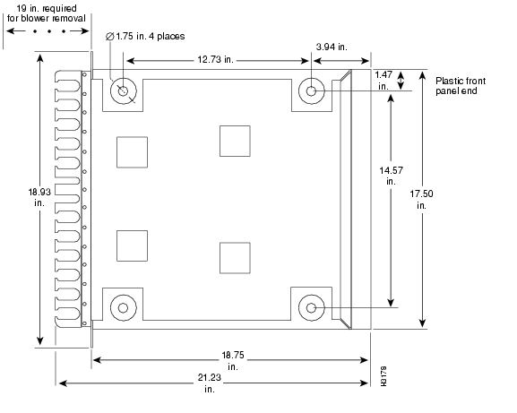
The router can be mounted in the rear of a rack. Before using a particular rack, check for obstructions (such as a power strip) that could impair rack-mount installation. If a power strip does impair a rear rack-mount installation, remove the power strip before installing the router in the rack and then replace it after the chassis is installed. As an alternative, the router can be mounted on an equipment shelf provided that the shelf and rack dimensions allow the router to be secured to the shelf and the overall configuration permits safe installation and access; however, we recommend rack-mount installation for the Cisco 7513, Cisco 7513-MX, and Cisco 7576. Figure 2-12 shows the chassis footprint and outer dimensions.
To use the rack-mounting hardware provided with the router, consider the following guidelines:
•
•
•
•
Figure 2-12 Chassis Footprint and Outer Dimensions (Cisco 7513, Cisco 7513-MX, and Cisco 7576)
Caution
When planning your Cisco 7513, Cisco 7513-MX, or Cisco 7576 rack installation, consider the following guidelines:
•
•
•
•
•
•
•
•
In addition to the preceding guidelines, we recommend you review the precautions for avoiding overtemperature conditions in the "General Equipment Rack Ventilation Considerations" section.
Environmental Monitoring and Reporting Overview for the Cisco 7500 Series
In the Cisco 7500 series routers, the environmental monitoring and reporting functions are controlled by the chassis interface (CI) board. These functions enable you to maintain normal system operation by identifying and resolving adverse conditions prior to loss of operation. The environmental monitoring functions constantly monitor the internal chassis air temperature and DC supply voltages and currents.
Each power supply monitors its own voltage and temperature and shuts itself down if it detects a critical condition within the power supply. If conditions reach shutdown thresholds, the system shuts down to avoid equipment damage from excessive heat. The reporting functions periodically log the values of measured parameters so that you can retrieve them for analysis later, and the reporting functions display warnings on the console if any of the monitored parameters exceed defined thresholds.
In addition to monitoring internal temperature and voltage levels, the system also monitors the fan tray or blower. If the fan tray or blower fails, the system displays a warning message on the console. If the blower is still not operating properly after 2 minutes, the system shuts down to protect the internal components against damage from excessive heat.
The following sections provide information on environmental monitoring, temperature and voltage thresholds, and environmental reporting functions in the Cisco 7500 series routers:
•
•
•
Cisco 7500 Series Environmental Monitoring
The temperature of the cooling air that flows through the processor slots is monitored by three sensors on the RSP: inlet, hotpoint, and exhaust.
The power supply DC voltages are monitored by the chassis interface (CI) and indicated by the systems as Normal, Critical, and Warning levels, as follows:
•
•
•
Processor shutdown occurs when the chassis interface detects a temperature or blower-failure condition that could result in physical damage to system components and has disabled DC power to all interface processors. DC power to the RSP, chassis interface, and fans or blower stays on, but no RSP-related processing takes place. Immediate action is required. DC power remains off until the inside temperature of the chassis reaches 40°C (104°F), at which point the system will restart, up to 15 times (if required). After the fifteenth restart, if the source of the shutdown has not been corrected, the system will execute a hard shutdown. Before any shutdown, the system logs the status of monitored parameters in NVRAM so that you can retrieve it later to help determine the cause of the problem.
Power supply shutdown occurs when an out-of-tolerance voltage, current, or temperature condition is detected within the power supply and it is shut down (or a shutdown is imminent). All DC power remains disabled until you toggle the power switch and correct the problem that caused the shutdown (if any).
This shutdown typically occurs for one of the following reasons:
•
•
•
Note
This achieves a hard shutdown of one router without affecting the other router. The RSP and IPs will remain disabled until the power is manually recycled. This allows you to choose a suitable time to recycle the power when it will not adversely affect your users.In the Cisco 7507, Cisco 7507-MX, Cisco 7513, Cisco 7513-MX, and Cisco 7576, a blower failure is indicated when the blower impeller has stopped turning. A warning message is displayed on the console, and the system will continue operating until it shuts itself down because of overheating, or until you shut it down.
Cisco 7500 Series Temperature and Voltage Thresholds
If the air temperature exceeds a defined threshold, the system processor displays warning messages on the console terminal, and if the temperature exceeds the shutdown threshold, it shuts down the system. The system stores the present parameter measurements for both temperature and DC voltage in NVRAM, so that you can retrieve them later as a report of the last shutdown parameters.
The power supplies monitor internal power supply temperature and voltages. A power supply is either within tolerance (Normal) or out of tolerance (Critical or Warning levels). If an internal power supply temperature or voltage reaches a critical level, the power supply shuts down without any interaction with the system processor.
If the system detects that AC or DC input power is dropping, but it is able to recover before the power supply shuts down, it logs the event as an intermittent power failure. The reporting functions display the cumulative number of intermittent power failures logged since the last power up.
The following sections include the temperature and voltage threshold specifications for the Cisco 7500 series routers:
•
•
•
Note
Cisco 7505 Temperature and Voltage Thresholds
Table 2-2 Table 2-2 lists temperature thresholds for the first four processor-monitored levels. (The system displays all temperatures in Celsius only.) Table 2-3 lists the DC power thresholds for the Normal and Critical power supply-monitored levels.
)
Cisco 7507 and Cisco 7507-MX Temperature and Voltage Thresholds
Table 2-4 lists temperature thresholds for the three processor-monitored levels. (The system displays all temperatures in Celsius only.) Table 2-5 lists the DC power thresholds for the Normal and Critical power supply-monitored levels.
Cisco 7513, Cisco 7513-MX, and Cisco 7576 Temperature and Voltage Thresholds
Table 2-6 lists temperature thresholds for the three processor-monitored levels. (The system displays all temperatures in Celsius only.) Table 2-7 lists the DC power thresholds for the Normal and Critical power supply-monitored levels.
Table 2-6 Typical Processor-Monitored Temperature Thresholds (Cisco 7513, Cisco 7513-MX, and Cisco 7576)
Inlet
10-40°C
44°C
50°C
-
Hotpoint
10-40°C
54°C
60°C
-
Exhaust
10-40°C
-
-
-
Processors
-
-
-
70°C
Power supply
-
-
-
75°C 1
Restart
40°C
-
-
-
1 Processor-monitored power supply shutdown is not supported on the Cisco 7576.
Cisco 7500 Series Environmental Reports
The system displays warning messages on the console if chassis interface-monitored parameters exceed a desired threshold or if a blower failure occurs. You can also retrieve and display environmental status reports with the show environment, show environment all, show environment last, and show environment table commands. Parameters are measured and reporting functions are updated every 60 seconds.
Note
Caution
The following sections include the environmental reporting and fan or blower functions for the Cisco 7500 series routers:
•
•
•
•
Note
Cisco 7505 Environmental show Command Examples
In the Cisco 7505, the show environment command display reports the current environmental status of the system. The report displays the date and time of the query, the refresh times, the overall system status, and any parameters that are out of the normal values. No parameters are displayed if the system status is normal. The example that follows shows the display for a system in which all monitored parameters are within normal status range:
Router# show envEnvironmental StatisticsEnvironmental status as of Wed 5-10-1995 16:42:48Data is 0 second(s) old, refresh in 60 second(s)All Environmental Measurements are within specificationsIf the environmental status is not normal, the system reports the worst-case status level in the last line of the display, instead of the status summary that is shown in the last line of the preceding example. In the Cisco 7505, the show environment last command retrieves and displays the NVRAM log of the reason for the last shutdown and the environmental status at that time. If no status is available, it displays the reason as unknown.
Router# show env lastEnvironmental StatisticsEnvironmental status as of Wed 5-10-1995 16:42:48Data is 10 second(s) old, refresh in 50 second(s)All Environmental Measurements are within specificationsLAST Environmental StatisticsEnvironmental status as of Wed 5-10-1995 12:22:43Power Supply: 600W, OFFNo Intermittent Powerfails+12 volts measured at 12.05(V)+5 volts measured at 4.82(V)-12 volts measured at -12.00(V)+24 volts measured at 23.90(V)Air-Flow temperature measured at 32(C)Inlet temperature measured at 26(C)In the Cisco 7505, the show environment table command displays the temperature and voltage thresholds for each monitored status level, which are the same as those listed in Table 2-2 and Table 2-3. The current measured values are displayed with the unit of measure noted, (V) or (C), and each is listed below a column heading that indicates its current status level. Measurements that fall within the Normal range are displayed in the Normal column of the table, whereas measurements that have reached a critical level are shifted to the Critical column, and so on.
In the following example, all current measured values fall within the Normal status range. The first voltage parameter in the table, +12(V), shows that the Normal range for the +12V sense spans 10.20V through 13.80V. The current measured value, 12.05V, falls within that range and is therefore displayed in the Normal column.
Router# show env tableEnvironmental StatisticsEnvironmental status as of Wed 5-10-1995 18:50:21Data is 46 second(s) old, refresh in 14 second(s)WARNING: Fan has reached CRITICAL levelVoltage Parameters:SENSE CRITICAL NORMAL CRITICAL-------|--------------------|------------------------|------------------+12(V) 10.20 12.05(V) 13.80+5(V) 4.74 4.96(V) 5.26-12(V) -10.20 -12.05(V) -13.80+24(V) 20.00 23.80(V) 28.00Temperature Parameters:SENSE WARNING NORMAL WARNING CRITICAL SHUTDOWN------|-------------|------------|-------------|--------------|---------Inlet 10 32(C) 39 46 64Air-flow 10 40(C) 70 77 88The following example shows only the Temperature Parameters section of the table. In this example, the measured value at the inlet sensor is 41°C, which falls within the warning range (39°C through 46°C) and is therefore displayed in the Warning column.
Temperature Parameters:SENSE WARNING NORMAL WARNING CRITICAL SHUTDOWN------|-------------|------------|-------------|--------------|-----Inlet 10 39 41(C) 46 64Air-flow 10 40(C) 70 77 88In the Cisco 7505, the show environment all command displays an extended report that includes all the information in the show environment command display, plus the power supply status, the number of intermittent power failures (if any) since the system was last powered on, and the measured values at the temperature sensors and the DC lines. The refresh time indicates that the parameters will be measured again in 29 seconds; any changes to a measurement will not be reflected in the display until at least 40 seconds have elapsed and the current information is refreshed.
Router# show env allEnvironmental StatisticsEnvironmental status as of Wed 5-10-1995 19:10:41Data is 31 second(s) old, refresh in 29 second(s)WARNING: Fan has reached CRITICAL levelPower Supply: 600W AC (or 600W DC)No Intermittent Powerfails+12 volts measured at 12.00(V)+5 volts measured at 5.02(V)-12 volts measured at -12.05(V)+24 volts measured at 23.70(V)Airflow temperature measured at 35(C)Inlet temperature measured at 26(C)When the system power is on, all six fans in the fan array must be operational. If the system detects a failed or failing fan, it will display a warning message on the console screen. If the condition is not corrected within 2 minutes, the entire system will shut down to avoid an overtemperature condition and possible damage.
The system uses a Hall Effect signal to monitor the six fans in the array. The current to the fans and the magnetic field generated by the fans' rotation generate a voltage, which the system monitors to determine if all of the fans are operating. If the monitored voltage signal drops below a specified value, the system assumes a fan failure and initiates a system shutdown.
In the following example, the system has detected an out-of-tolerance fan, which it interprets as a fan failure. The failure message is displayed for 2 minutes before the system shuts down.
%ENVM-2-FAN: Fan array has failed, shutdown in 2 minutesIf the system does shut down because of a fan failure, the system will display the following message on the console screen and in the environment display and in the show environment command display when the system restarts:
Queued messages:%ENVM-1-SHUTDOWN: Environmental Monitor initiated shutdownCisco 7507 and Cisco 7507-MX Environmental show Command Examples
In the Cisco 7507 and Cisco 7507-MX, the show environment command display reports the current environmental status of the system. The report displays parameters that are out of the normal values. No parameters are displayed if the system status is normal. The example that follows shows the display for a system in which all monitored parameters are within normal status range.
Router# show envAll measured values are normalIf the environmental status is not normal, the system reports the worst-case status level in the last line of the display.
In the Cisco 7507 and Cisco 7507-MX, the show environment last command retrieves and displays the NVRAM log showing the reason for the last shutdown (if the shutdown was related to voltage or temperature) and the environmental status at that time. Air temperature is measured and displayed, and the DC voltages supplied by the power supply are also displayed.
Following is sample output of the show env last command:
Router# show env lastRSP(2) Inlet previously measured at 27C/80FRSP(2) Hotpoint previously measured at 38C/100FRSP(2) Exhaust previously measured at 31C/87F+12 Voltage previously measured at 12.17+5 Voltage previously measured at 5.19-12 Voltage previously measured at -12.17+24 Voltage previously measured at 23.40In the Cisco 7507 and Cisco 7507-MX, the show environment table command displays the temperature and voltage thresholds for each of the three RSP temperature sensors for each monitored status level: low critical, low warning, high warning, and high critical, which are the same as those listed in Table 2-4 and Table 2-5. The slots in which the RSP can be installed are indicated in parentheses (slot 2 and slot 3). Also listed are the shutdown thresholds for the processor boards and power supplies. Following is sample output of the show env table command:
Router# show env tableSample Point LowCritical LowWarning HighWarning HighCriticalRSP(2) Inlet 44C/111F 50C/122FRSP(2) Hotpoint 54C/129F 60C/140FRSP(2) Exhaust 101C/213F 101C/213CRSP(3) Inlet 44C/111F 50C/122FRSP(3) Hotpoint 54C/129F 60C/140FRSP(3) Exhaust 101C/213F 101C/213F+12 Voltage 10.90 11.61 12.82 13.38+5 Voltage 4.49 4.74 5.25 5.52-12 Voltage -10.15 -10.76 -13.25 -13.86+24 Voltage 19.06 21.51 26.51 28.87Shutdown boards at 101C/213FShutdown power supplies at 101C/213FIn the Cisco 7507 and Cisco 7507-MX, the show environment all command displays an extended report that includes the arbiter type, backplane type, power supply type (AC or DC), wattage and status, the number and type of intermittent power failures (if any) since the system was last powered on, and the currently measured values at the RSP temperature sensors and the power supply voltages. The show environment all command also displays a report showing which slots in the Cisco 7507 or Cisco 7507-MX are occupied (indicated by an X) and which are empty.
Active fault conditions are indicated when the blower or power supply has failed or is not present. The system expects to see one blower in the Cisco 7507 or Cisco 7507-MX, the main system blower.
The system blower is designated #1. The active fault condition in the following example shows that there is no power supply installed in power bay A because the display indicates that power supply #1 (in the lower bay) is removed.
There are four active trip points: restart OK, temperature warning, board shutdown, and power supply shutdown. (There are no active trip points shown in the following example.) The soft shutdowns entry refers to the number of times the system will reset itself before it executes a complete system (or hard) shutdown.
The current temperature measurements at the three RSP sensors are displayed as inlet, hotpoint, and exhaust. The shutdown temperature source is the hotpoint sensor, which is located toward the center of the RSP. System voltage measurements are also displayed, followed by the system current measurements and power supply wattage calculation. Following is sample output of the show env all command:
Router# show env allArbiter type 1, backplane type 7507 (id 4)Power supply #1 is removed (id 3), power supply #2 is 700W (id 2)Active fault conditions: noneActive trip points: Restart_Inhibit15 of 15 soft shutdowns remaining before hard shutdown
Note
0123456Dbus slots: XX XXXinlet hotpoint exhaustRSP(3) 16C/60F 24C/71F 20C/68FShutdown temperature source is 'hotpoint' slot3 (requested slot2)+12V measured at 11.84+5V measured at 5.05-12V measured at -11.84+24V measured at 23.78+2.5 reference is 2.46PS1 +5V Current measured at 42.35 A (capacity 200 A)PS1 +12V Current measured at 6.86 A (capacity 35 A)PS1 -12V Current measured at 0.55 A (capacity 3 A)PS1 output is 296 WWhen the system power is on, the blower must be operational. If the system detects that the blower has failed or is failing, it will display a warning message on the console screen. The entire system will shut down when the voltage at the hotpoint sensor (center of the RSP) reaches a predetermined value.
In the following example, the system has detected an out-of-tolerance blower, which it interprets as a blower failure.
%ENVM-2-FAN: Blower has failed.When the temperature reaches a critical level, the system will display the following message on the console screen and in the show environment command display when the system restarts:
Queued messages:%ENVM-1-SHUTDOWN: Environmental Monitor initiated shutdownCisco 7513 and Cisco 7513-MX Environmental show Command Examples
In the Cisco 7513 and Cisco 7513-MX, the show environment command display reports the current environmental status of the system. The report displays parameters that are out of the normal values. No parameters are displayed if the system status is normal. The example that follows shows the display for a system in which all monitored parameters are within normal status range.
Note
Following is sample output of the show env command:
Router# show envAll measured values are normalIf the environmental status is not normal, the system reports the worst-case status level in the last line of the display.
In the Cisco 7513 and Cisco 7513-MX, the show environment last command retrieves and displays the NVRAM log showing the reason for the last shutdown (if the shutdown was related to voltage or temperature) and the environmental status at that time. Air temperature is measured and displayed; the DC voltages supplied by the power supply are also displayed.
Following is sample output of the show env last command:
Router# show env lastRSP(6) Inlet previously measured at 27C/80FRSP(6) Hotpoint previously measured at 38C/100FRSP(6) Exhaust previously measured at 31C/87F+12 Voltage previously measured at 12.17+5 Voltage previously measured at 5.19-12 Voltage previously measured at -12.17+24 Voltage previously measured at 23.40In the Cisco 7513 and Cisco 7513-MX, the show environment table command displays the temperature and voltage thresholds for each of the three RSP temperature sensors for each monitored status level: low critical, low warning, high warning, and high critical, which are the same as those listed in Table 2-6 and Table 2-7. The slots in which the RSP can be installed are indicated in parentheses (slot 6 and slot 7). Also listed are the shutdown thresholds for the processor boards and power supplies.
Following is sample output of the sh env table command:
Router# show env tableSample Point LowCritical LowWarning HighWarning HighCriticalRSP(6) Inlet 44C/111F 50C/122FRSP(6) Hotpoint 54C/129F 60C/140FRSP(6) ExhaustRSP(7) Inlet 44C/111F 50C/122FRSP(7) Hotpoint 54C/129F 60C/140FRSP(7) Exhaust+12 Voltage 10.76 11.37 12.64 13.24+5 Voltage 4.49 4.74 5.25 5.52-12 Voltage -10.15 -10.76 -13.25 -13.86+24 Voltage 19.06 21.51 26.51 28.87Shutdown boards at 101C/213FShutdown power supplies at 101C/213F
Note
In the Cisco 7513 and Cisco 7513-MX, the show environment all command displays an extended report that includes the arbiter type, backplane type, power supply type (AC or DC), wattage and status, the number and type of intermittent power failures (if any) since the system was last powered on, and the currently measured values at the RSP temperature sensors and the DC-input lines. The show environment all command also displays a report showing which slots in the Cisco 7513 or Cisco 7513-MX are occupied (indicated by an X) and which are empty.
Active fault conditions are indicated when the blower or power supply has failed or is not present (as "Blower #3" indicates in the following example). The system expects to see three blowers or fans in the Cisco 7513 or Cisco 7513-MX: the main system blower, and one fan in each power supply. The system blower is designated #1, the power supply fan in power bay A is #2, and the power supply fan in power bay B is #3. The active fault condition in the following example shows that there is no power supply installed in power bay B because the display indicates that power supply #2 (in power bay B) is removed. System blower speed is displayed as a percentage of maximum.
There are four active trip points: restart OK, temperature warning, board shutdown, and power supply shutdown. (There are no active trip points shown in the following example.) The soft shutdowns entry refers to the number of times the system will reset itself before it executes a complete system (or hard) shutdown.
The current temperature measurements at the three RSP sensors are displayed as inlet, hotpoint, and exhaust. The shutdown temperature source is the hotpoint sensor, which is located toward the center of the RSP. System voltage measurements are also displayed, followed by the system current measurements and power supply wattage calculation.
Note
Following is sample output of the show env all command:
Router# show env allArbiter type 1, backplane type 7513 (id 2)Power supply #1 is 1200W AC (id 1), power supply #2 is removed (id 7)Active fault conditions: Blower #3Fan speed is 50%Active trip points: none15 of 15 soft shutdowns remaining before hard shutdown
Note
10123456789012Dbus slots: XX XXXX XXXXinlet hotpoint exhaustRSP(6) 24C/75F 35C/95F 29C/84FShutdown temperature source is 'hotpoint' slot6 (requested slot6)+12V measured at 12.17+5V measured at 5.19-12V measured at -12.26+24V measured at 24.44+2.5 reference is 2.49PS1 +5V Current measured at 42.35 A (capacity 200 A)PS1 +12V Current measured at 6.86 A (capacity 35 A)PS1 -12V Current measured at 0.55 A (capacity 3 A)PS1 output is 296 WWhen the system power is on, the blower must be operational. If the system detects that the blower has failed or is failing, it will display a warning message on the console screen. The entire system will shut down when the voltage at the hotpoint sensor (center of the RSP) reaches a predetermined value.
In the following example, the system has detected an out-of-tolerance blower, which it interprets as a blower failure.
%ENVM-2-FAN: Blower has failed.When the temperature reaches a critical level, the system will display the following message on the console screen and in the show environment command display when the system restarts:
Queued messages:%ENVM-1-SHUTDOWN: Environmental Monitor initiated shutdownCisco 7576 Environmental show Command Examples
In the Cisco 7576, the show environment command reports the current environmental status of the system. The report displays parameters that are out of the normal values. No parameters are displayed if the system status is normal. The example that follows shows the display for a system in which all monitored parameters are within normal status range.
Following is sample output of the show env command:
Router# show envAll measured values are normalIf the environmental status is not normal, the system reports the worst-case status level in the last line of the display.
In the Cisco 7576, the show environment last command retrieves and displays the NVRAM log showing the reason for the last shutdown (if the shutdown was related to voltage or temperature) and the environmental status at that time. Air temperature is measured and displayed; the DC voltages supplied by the power supply are also displayed.
Following is sample output of the show env last command:
Router# show env lastRSP(6) Inlet previously measured at 21C/69FRSP(6) Hotpoint previously measured at 29C/84FRSP(6) Exhaust previously measured at 25C/77F+12 Voltage previously measured at 12.12+5 Voltage previously measured at 5.15-12 Voltage previously measured at -12.17+24 Voltage previously measured at 23.87In the Cisco 7576, the show environment table command displays the temperature and voltage thresholds for each of the three RSP temperature sensors for each monitored status level: low critical, low warning, high warning, and high critical, which are the same as those listed in Table 2-6 and Table 2-7. The slots in which the RSP can be installed are indicated in parentheses (slot 6 and slot 7). Also listed are the shutdown thresholds for the processor boards and power supplies.
Following is sample output of the sh env table command:
Router# show env table
Note
In the Cisco 7576, the show environment all command displays an extended report that includes the arbiter type, backplane type, power supply type (AC or DC), wattage and status, the number and type of intermittent power failures (if any) since the system was last powered on, and the currently measured values at the RSP temperature sensors and the DC-input lines. The show environment all command also reports which slots in the Cisco 7576 are occupied (indicated by an X) and which are empty.
Active fault conditions are indicated when the blower or power supply has failed or is not present. The system expects to see three blowers or fans in the Cisco 7576: the main system blower, and one fan in each power supply. The system blower is designated #1, the power supply fan in power bay A is #2, and the power supply fan in power bay B is #3.
An example of an active fault condition includes the absence of a power supply. In the above example a power supply is installed in both power bays; therefore no active fault condition exists. There are three active trip points: restart OK, temperature warning, and board shutdown. (There are no active trip points shown in the following example.) The soft shutdown entry refers to the number of times the system will reset itself before it executes a complete system (or hard) shutdown.
The current temperature measurements at the three RSP sensors are displayed as inlet, hotpoint, and exhaust. The shutdown temperature source is the hotpoint sensor, which is located toward the center of the RSP. System voltage measurements are also displayed, followed by the system current measurements and power supply wattage calculation.
![]()
![]()
![]()
![]()
![]()
![]()
![]()
![]()
Posted: Thu Mar 24 11:09:04 PST 2005
All contents are Copyright © 1992--2005 Cisco Systems, Inc. All rights reserved.
Important Notices and Privacy Statement.