|
|

Table Of Contents
Interface Processor Installation and Configuration Guide
Confirming Interface Processor Compatibility
Determining Board Part Number and Revision
Interface Processor Description
Interface Processor Descriptions and Part Numbers
Slot Locations in the Cisco 7000 and Cisco 7500 Series Routers
List of Required Parts and Tools
Electrical Equipment Guidelines
Preventing Electrostatic Discharge Damage
Environmental and Regulatory Specifications
Guidelines for Interface Processor Removal and Installation
Interface Processor Installation Procedures
Removing an Interface Processor
Installing an Interface Processor
Connecting the Interface Processor Cables
Configuring the Interface Processor
Using the EXEC Command Interpreter
Upgrading Interface Processor Microcode Images
Obtaining Technical Assistance
Interface Processor Installation and Configuration Guide
Customer Order Number: DOC-784211=
Introduction
This document contains installation and configuration procedures for interface processors installed in your Cisco 7000 series and Cisco 7500 series router. Interface processors support online insertion and removal (OIR), which allows interface processor insertion and removal without first shutting down the system to maximize router availability.
For more complete information, refer to the specific installation and configuration guide for your interface processor at http://www.cisco.com/univercd/cc/td/doc/product/core/cis7505/interpro/index.htm, and the appropriate configuration note, or the appropriate Cisco IOS documentation, to more completely configure your interface processor.
Contents
This document includes the following sections:
•
Confirming Interface Processor Compatibility
•
•
•
•
•
•
Related Documentation
All of the following documentation mentioned is available online, on the Documentation CD-ROM, or as printed documents. For a complete list of documentation, refer to the Cisco 7500 Series Router Documentation flyer (part number DOC-7812955) that shipped with your interface processor, or view it online at http://www.cisco.com/univercd/cc/td/doc/product/core/cis7505/12955fly.htm.
Your router and the Cisco IOS software running on it contain extensive features and functionality, which are documented in the following resources:
•
For configuration information and support, refer to the Cisco IOS software configuration documentation set that corresponds to the software release installed on your Cisco hardware.
•
–
–
–
–
–
–
–
–
–
–
–
–
–
–
–
–
For additional information on configuring the Cisco 7000 series and Cisco 7500 series routers and interface processors, the following documentation resources are available:
•
For hardware installation and configuration information on each type of interface processor, refer to the following index of titles at www.cisco.com/univercd/cc/td/doc/product/core/cis7505/interpro/index.htm
–
www.cisco.com/univercd/cc/td/doc/product/core/cis7505/interpro/atm_/index.htm–
www.cisco.com/univercd/cc/td/doc/product/core/cis7505/interpro/channel/index.htm–
–
www.cisco.com/univercd/cc/td/doc/product/core/cis7505/interpro/ethernet/index.htm–
www.cisco.com/univercd/cc/td/doc/product/core/cis7505/interpro/fddi/index.htm–
www.cisco.com/univercd/cc/td/doc/product/core/cis7505/interpro/hssi/index.htm–
www.cisco.com/univercd/cc/td/doc/product/core/cis7505/interpro/ser_chan/index.htm–
www.cisco.com/univercd/cc/td/doc/product/core/cis7505/interpro/sonet/index.htm–
www.cisco.com/univercd/cc/td/doc/product/core/cis7505/interpro/token/index.htm•
For hardware installation and maintenance information on the Cisco 7000 series routers, refer to the Cisco 7000 Hardware Installation and Maintenance Guide online at http://www.cisco.com/univercd/cc/td/doc/product/core/cis7000/7000_him/index.htm.
•
For hardware installation and maintenance information on the Cisco 7500 series routers, refer to the Quick Start Guide that shipped with your router, or refer to the Cisco 7500 Installation and Configuration Guide online at http://www.cisco.com/univercd/cc/td/doc/product/core/cis7505/cicg7500/index.htm.
•
–
–
•
Confirming Interface Processor Compatibility
This section describes how to determine if your interface processor is compatible with your existing equipment.
This section includes the following information:
Determining Board Part Number and Revision
Process Flowchart
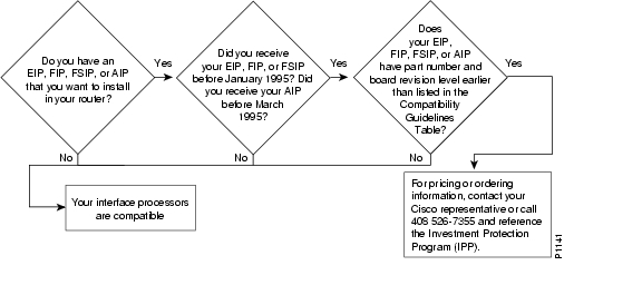
Before installing a new interface processor, determine if it is compatible with your existing legacy interface processors, using the following flowchart ( Figure 1) in conjunction with Table 1. To determine your board number and revision, refer to the "Determining Board Part Number and Revision" section.
Figure 1 Interface Processor Compatibility Flowchart
Table 1 Interface Processor Compatibility Guidelines 1
CX-AIP-SS
73-1188-02
D0 or later
CX-AIP-SM
73-1188-02
D0 or later
CX-AIP-TM
73-1188-02
D0 or later
CX-AIP-DS3
-
Does not require an upgrade
CX-AIP-E3
-
Does not require an upgrade
CX-EIP2
73-1129-02
N0 or later
CX-EIP4
73-1132-02
N0 or later
CX-EIP6
73-0906-02
N0 or later
CX-FIP-MM
73-0892-03
M0 or late
CX-FIP-MS
73-1093-03
M0 or later
CX-FIP-SM
73-1090-03
M0 or later
CX-FIP-SS
73-1087-03
M0 or later
CX-FSIP4
73-1187-05
A0 or later
CX-FSIP8
73-1126-05
A0 or later
All other interface processors
-
-
1 Any interface processors not specifically listed in the table are compatible with Cisco 7500 series or RSP7000.
2 A board part number is compatible with Cisco 7500 series or Cisco 7000 series with an RSP7000 processor option if it is equal to or greater than those listed in this column.
3 The suffix of the part number reflects the fab revision. (See the "Determining Board Part Number and Revision" section)
4 It may not be necessary to check the board revision level, because the part number suffix itself may determine compatibility.
5 A board revision should be checked only if the part number suffix is equal to those listed in the table. In this case, the board revision must be greater than or equal to those listed in the table.
Determining Board Part Number and Revision
You can determine the part number and board revision of your interface processor in one of two ways:
•
•
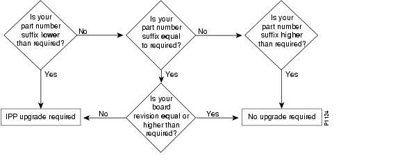
Figure 2 provides a flowchart to determine if your new interface processor is compatible with your existing interface processor, using board part numbers and revision levels.
Figure 2 Determining Compatibility from Board Part Numbers and Revision Levels
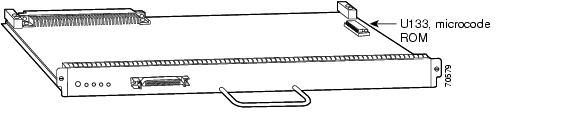
Inspecting the Physical Board
The part number and board revision are typically silk-screened along an edge of the interface processor printed circuit board, as shown in Figure 3:
Figure 3 Diagram of Interface Processor, Board, and Carrier
Using the Show Diagbus Command
You can also use the show diagbus command to determine the part number and board revision of your interface processor. The following is an example of a compatible CX-EIP6:
Router# show diagbusSlot 0: Physical slot 0, ~physical slot 0xF, logical slot 0, CBus 0Microcode Status 0x0Master Enable, LED, WCS LoadedBoard is analyzedEEPROM format version1 EIP controller, HW rev 1.5, board revision B0Serial number: 01652924 Part number: 73-0906-04Test history: 0x00 RMA number: 00-00-00Flags: cisco 7000 board; 7500 compatibleEEPROM contents (hex):0x20: 01 00 01 05 00 19 38 BC 49 03 8A 04 00 00 00 000x30: 58 00 00 00 00 00 00 00 00 00 00 00 00 00 00 00Slot database information:Flags: 0x4 Insertion time: 980 (5d20 ago)Interface Processor Description
This section describes interface processors and includes the following information:
•
•
•
•
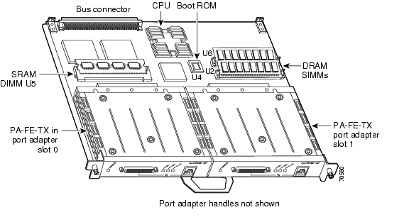
Interface processors are modular, self-contained boards with one or more network interface connectors between the system bus (inside Cisco 7000 series and Cisco 7500 series routers) and the network. Interface processors have one network connection (see Figure 4). Versatile Interface Processors (VIPs) support up to two network connections via the port adapters (see Figure 5). However, the focus of this guide is interface processors.
For more information on second generation VIPs (VIP2s), refer to http://www.cisco.com/univercd/cc/td/doc/product/core/cis7505/vip1/vip2/index.htm. For more information on fourth generation VIPs (VIP4s), refer to http://www.cisco.com/univercd/cc/td/doc/product/core/cis7505/vip1/vip4/index.htm.
Figure 4 Single-Port Interface Processor Example - High-Speed Serial Interface Processor Shown
Figure 5 Dual-Port Interface Processor Example - VIP2-40 with an FE-TX Port Adapter and a Blank Port Adapter Shown
Interface processors provide the following electrical interface media:
•
•
•
•
•
•
•
•
•
•
•
•
•
•
Interface Processor Descriptions and Part Numbers
Table 2 lists the interface processors by type, with descriptions and part numbers.
Table 2 Interface Processor Descriptions and Part Numbers
ATM Interface Processors:
AIP
ATM Interface Processor, 1 TAXI multimode port, 100 Mbps
CX-AIP-TM
ATM Interface Processor, 1 SONET/SDH single-mode port, 155 Mbps
CX-AIP-SS
ATM Interface Processor, 1 E3 coaxial port, 34 Mbps
CX-AIP-E3
ACIP
ATM Cable Interface Processor, 1 SONET/SDH multimode port, 155 Mbps
CX-ACIP-SM
Channel Interface Processors:
CIP2
Second-generation Channel Interface Processor with single parallel channel
CX-CIP2-PCA11
Second-generation Channel Interface Processor with dual parallel channel
CX-CIP2-PCA2 1
Second-generation Channel Interface Processor with single ESCON channel
CX-CIP2-ECA1
Second-generation Channel Interface Processor with dual ESCON channel
CX-CIP2-ECA2
Second-generation Channel Interface Processor with single ESCON channel and single parallel channel
CX-CIP2-ECAP1 1
CT3IP
Channelized T3 Interface Processor, 1 port, 1 MB SRAM, 16 MB DRAM
CT3IP-20
Channelized T3 Interface Processor, 1 port, 2 MB SRAM, 32 MB DRAM
CT3IP-40
Channelized DS3 Interface Processor, Model 50, 4 MB SRAM, 32 MB SDRAM
CT3IP-50
CT3IP-50
May be ordered with the following memory options: 8 MB SRAM Option for VIP2-50 (Packet Memory) 64 MB SDRAM Option for VIP2-50 (Program Memory) 128 SDRAM Option for VIP2-50 (Program Memory)
MEM-VIP250-8M-S
MEM-VIP250-64M-D
MEM-VIP250-128M-DDynamic Packet Transport OC12/STM4 (SRPIP) Interface Processor:
SRPIP
2xOC12/STM4c Multi-mode
SRPIP-OC12MM
Dynamic Packet Transport Interface Processor - OC12SMI
SRPIP-OC12SMI=
Dynamic Packet Transport Interface Processor - OC12SML
SRPIP-OC12SML
DPT-OC12 Single-mode extended reach Interface Processor
SRPIP-OC12SMX
Single-Mode, Intermediate Reach Ring Interface Processor
SRPIP-OC12SI
Single-Mode, Long-Reach Ring Interface Processor
SRPIP-OC12SL
Ethernet Interface Processors:
EIP
Ethernet Interface Processor, 2 ports
CX-EIP2
Ethernet Interface Processor, 4 ports
CX-EIP4
Ethernet Interface Processor, 6 ports
CX-EIP6
Fast Ethernet Interface Processors:
FEIP2
Second-Generation Fast Ethernet Interface Processor, 2 ports
FEIP2-2TX
Second-Generation Fast Ethernet Interface Processor, 2 ports
FEIP2-2FX
2-Port Fast Ethernet IP with Dist. Switching (100TX)
FEIP2-DSW-2TX
2-Port Fast Ethernet IP with Dist. Switching (100FX)
FEIP2-DSW-2FX
FDDI Interface Processors:
FIP
FDDI Interface Processor, 1 multimode to single-mode port
CX-FIP-MS
FDDI Interface Processor, 1 single-mode to multimode port
CX-FIP-SM
FSIP
Fast Serial Interface Processor, 4 ports
CX-FSIP4
Fast Serial Interface Processor, 8 ports
CX-FSIP8
Gigabit Ethernet Interface Processor:
GEIP
Gigabit Ethernet Interface Processor
GEIP
Enhanced Gigabit Ethernet Interface Processor
GEIP+
MultiChannel Interface Processors
MIP
MultiChannel Interface Processor, 1-port T1/PRI
CX-MIP-1CT1
SMIP
Service Provider MultiChannel Interface Processor, 2 T1 or ISDN PRI ports
CX-SMIP-2CT1
Serial Interface Processors
FSIP
Fast Serial Interface Processor, 4 ports
CX-FSIP4
Fast Serial Interface Processor, 8 ports
CX-FSIP8
SSIP
Standard Serial Interface Processor, 8-port
CX-SSIP8
Token Ring Interface Processors
TRIP
Token Ring Interface Processor, 2-port
CX-TRIP2
SONET Interface Processor
POSIP
Packet OC-3 Interface Processors
POSIP
Packet OC-3 Interface Processor, 1 single-mode port, 1 MB SRAM, 16 MB DRAM
POSIP-OC3-20-SM
Packet OC-3 Interface Processor, 1 multimode port, 1 MB SRAM, 16 MB DRAM
POSIP-OC3-20-MM
Packet OC-3 Interface Processor, 1 single-mode port, 2 MB SRAM, 32 MB DRAM
POSIP-OC3-40-SM
Packet OC-3 Interface Processor, 1 multimode port, 2 MB SRAM, 32 MB DRAM
POSIP-OC3-40-MM
Packet OC-3 Interface Processor, 1 single-mode port, 4 to 8 MB SRAM, 32 to 128 MB SDRAM
POSIP-OC3-50-SM
Packet OC-3 Interface Processor, 1 multimode port, 4 to 8 MB SRAM, 32 to 128 MB SDRAM
POSIP-OC3-50-MM
1 CX-CIP2-PCA1, CX-CIP2-PCA2, and CX-CIP2-ECAP1 ship with a cable that connects the CIP2 to cable CAB-PCA-VA. Cable CAB-PCA-VA provides the physical connection to the IBM bus and tag cable. Cable CAB-PCA-VA is required and is a standard IBM cable.
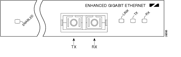
LEDs
The interface processor has several status LEDs on its faceplate, next to each port, which indicate conditions on that port. (See Figure 6.)
After system initialization, the enabled LED goes on to indicate that the FSIP has been enabled for operation.
The following conditions must be met before the interface processor is enabled:
•
•
•
If any one of these conditions is not met, or if the initialization fails, the enabled LED does not go on.
Refer to the specific installation and configuration guide for your interface processor at http://www.cisco.com/univercd/cc/td/doc/product/core/cis7505/interpro/index.htm to more completely understand the LEDs for your interface processor.
Figure 6 LEDs on a GEIP+ Example—Partial Faceplate View Shown
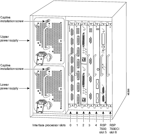
Slot Locations in the Cisco 7000 and Cisco 7500 Series Routers
Interface processors are installed in the interface processor slots of the Cisco 7000 series and Cisco 7500 series routers. Interface processors are keyed so they cannot be installed in noninterface processor slots, that is the route switch processor (RSP) slots.
The interface processor slots in the Cisco 7000 series and Cisco 7500 series routers are as follows:
•
•
•
•
•
•
Note
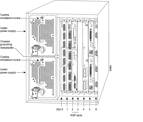
Figure 7 Cisco 7000 Interface Processor Slots - Rear View
Figure 8 Cisco 7010 Interface Processor Slots - Rear View
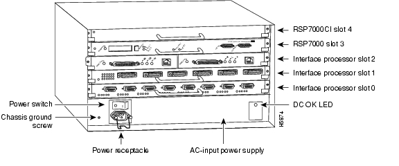
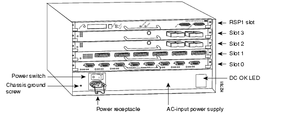
Figure 9 Cisco 7505 Interface Processor Slots - Rear View
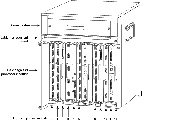
Figure 10 Cisco 7507 Interface Processor Slots - Rear View
Figure 11 Cisco 7513 and Cisco 7576 Interface Processor Slots - Rear View
Cables
This section describes the interface processor cables, and lists part numbers for each. Refer to the specific installation and configuration guide for your interface processor for additional information.
Table 3 Cisco 7000 Series and Cisco 7500 Series Interface Processor Cables
AIP
-
For DS3/E3, use CAB-ATM-DS3/E3
Other cables are user suppliedCIP2
Y cable that comes with CIP2
PCA V cable A
PCA V cable BCT3IP
-
User supplied
EIP
-
User supplied
FEIP
-
User supplied
FEIP2
-
User supplied
FIP
Mini-DIN-to-DIN transition
CAB-FMDD=
X.21 high-density male DTE
X.21 high-density female DCE
EIA/TIA-449 high-density male DTE
EIA/TIA-449 high-density female DCE
V.35 high-density male DTE
V.35 high-density female DCE
EIA/TIA-232 high-density male DTE
EIA/TIA-232 high-density female DCE
EIA-530 high-density male DTE
E1-G.703/G.704 twinax 120-ohm balanced, 16.4 ft
E1-G.703/G.704 DB-15 120-ohm balanced, 16.4 ft
E1-G.703/G.704 BNC 75-ohm unbalanced, 16.4 ftCAB-X21MT
CAB-X21FC
CAB-449MT
CAB-449FC
CAB-V35MT
CAB-V35FC
CAB-232MT
CAB-232FC
CAB-530MT
CAB-EI-TWINAX
CAB-EI-DB15
CAB-EI-BNCHIP3
Null modem, DTE, HSSI, 10 ft
Male to male, 10 ftCAB-HNUL=
CAB-HSI1=MIP or SMIP
DSX1 to CSU DB-15 thru
DSX1 to CSU DB-15 null
E1 ISDN PRI, 10 ft
E1 BNC 75-ohm unbalanced, 16.4 ft
E1 DB15 120-ohm balanced, 16.4 ft
E1 TWINAX 120-ohm balanced, 16.4 ftCAB-7KCT1DB15
CAB-7KCT1NULL
CAB-E1-PRI
CAB-E1-BNC
CAB-E1-DB15
CAB-E1-TWINAXPOSIP
-
User supplied
TRIP
-
User supplied
1 CIP2 models CX-CIP2-PCA1, CX-CIP2-PCA2, and CX-CIP2-ECAP1 ship with a cable that connects the CIP2 to cable CAB-PCA-VA
2 First generation VIP is no longer available. For informational purposes only.
3 The HIP uses the same cables as the PA-H and PA-2H port adapters.
Specifications
The interface processor physical specifications are listed in Table 4.
Installation Prerequisites
This section provides important prerequisites you should observe regarding interface processor software, hardware, and microcode.
•
Hardware Prerequisites
Interface processors operate in the Cisco 7000 or Cisco 7500 series routers with either of the following processor types:
•
–
–
•
Software Prerequisites
For the specific minimum software requirements for your interface processor, refer to the Software Advisor at http://www.cisco.com/cgi-bin/Support/CompNav/Index.pl, and the installation and configuration guide for your specific interface processor at http://www.cisco.com/univercd/cc/td/doc/product/core/cis7505/interpro/index.htm.
Microcode Prerequisites
Microcode, also known as firmware, is a set of processor-specific software instructions that enables and manages the features and functions of a specific processor type. At system startup or reload, the system loads the microcode for each processor type present in the system.
The interface processor microcode boot image resides in a Flash memory device on the interface processor motherboard. The entire interface processor microcode image is delivered on a Flash memory card, on floppy disks, or is available via download from Cisco.com.
New microcode is released to enable new features, improve performance, or fix bugs in earlier versions. The Cisco 7000 series and Cisco 7500 series routers feature downloadable software and microcode for most upgrades. These features enable you to download new (upgraded) images remotely, store the images in router memory, and load the new images at system startup without having to physically access the router. You can store multiple versions for a specific processor type in Flash memory, and use configuration commands to specify which version the system should load at startup. All interfaces of the same type (for example, all CIP2s) use the same microcode image.
Caution
By default, the interface processor microcode is loaded from either onboard Flash memory (if you have a Cisco 7000 or Cisco 7010 router with an RP) or the Flash memory card in slot0 for the Cisco 7500 series routers. The default interface processor microcode version can be found by entering the show microcode command.
The following is a partial-display example of the show microcode command output for a second generation channel interface processor (CIP2):
Router# show microcodeMicrocode bundled in systemCard MicrocodeType Version device:filename---- --------- -------------------(additional display text omitted from this example)CIP2 22-15 slot0:cip22-15(additional display text omitted from this example)Microcode flash default imagesList of Required Parts and Tools
Following are the tools required for interface processor replacement:
•
•
•
•
Safety Guidelines
Following are safety guidelines that you should follow when working with any equipment that connects to electrical power or telephone wiring. This section also includes safety and ESD-prevention guidelines to help you avoid injury and damage to the equipment.
Warning
Safety Warnings
Electrical Equipment Guidelines
Follow these basic guidelines when working with any electrical equipment:
•
•
•
•
•
•
Telephone Wiring Guidelines
Use the following guidelines when working with any equipment that is connected to telephone wiring or to other network cabling:
•
•
•
•
Preventing Electrostatic Discharge Damage
Electrostatic discharge (ESD) damage, which can occur when electronic cards or components are improperly handled, results in complete or intermittent failures. Port adapters and processor modules consist of printed circuit boards that are fixed in metal carriers. Electromagnetic interference (EMI) shielding and connectors are integral components of the carrier. Although the metal carrier helps to protect the board from ESD, use a preventive antistatic strap during handling.
Following are guidelines for preventing ESD damage:
•
•
•
•
•
•
•
•
Caution
Environmental and Regulatory Specifications
Each interface processor model and all supported port adapters meet the environmental and regulatory specifications listed in Table 5.
Guidelines for Interface Processor Removal and Installation
This section describes the mechanical functions of system components and emphasizes the importance of following correct procedures to avoid unnecessary board failures. Specific procedures follow these general background and safety guidelines in the "Interface Processor Installation Procedures" section. For information on configuring interfaces, refer to the specific interface processor installation and configuration guide at http://www.cisco.com/univercd/cc/td/doc/product/core/cis7505/interpro/index.htm.
After an interface processor is reinstalled, the system brings on line only interfaces that match the current configuration and were previously configured as up; all others require that you configure them with the configure command.
Caution
Note
For proper handling of interface processors during installation or removal, see Figure 12.
All interface processors have ejector levers that allow you to firmly seat an interface processor in the interface processor slot (see Figure 13). The function of the ejector levers is to align and seat the card connectors in the backplane. Failure to use the ejector levers and insert the interface processor properly can disrupt the order in which the pins make contact with the backplane.
Follow the installation and removal instructions carefully, and review the following examples of incorrect insertion practices and results:
•
•
•
Even if the connector pins are not damaged, the pins mating with and disconnecting from the backplane will cause the system to interpret a board failure. Using the ejector levers ensures that the board connector mates with the backplane in one continuous movement.
•
It is also important to use the ejector levers when removing an interface processor to ensure that the board connector pins disconnect from the backplane in the logical sequence expected by the system. Any processor module (interface processor or RSP) that is only partially connected to the backplane can hang the bus. (Detailed steps for correctly installing and removing an interface processor follow in the "Interface Processor Installation Procedures" section.)
For additional information, refer to the installation and configuration guide for your interface processor available online at http://www.cisco.com/univercd/cc/td/doc/product/core/cis7505/interpro/index.htm, on the Documentation CD-ROM, or as printed documents. Refer to the Cisco 7500 Series Router Documentation flyer (part number DOC-7812955) that shipped with your interface processor, or view it at http://www.cisco.com/univercd/cc/td/doc/product/core/cis7505/12955fly.htm.
Interface Processor Installation Procedures
The following sections describe the procedures for removing or installing an interface processor. (See the "Guidelines for Interface Processor Removal and Installation" section before removing an interface processor while power to the system is on.)
Caution
Note
Shutting Down an Interface
If you are installing a new interface processor or replacing an existing interface processor, proceed to the "Removing an Interface Processor" section.
If you are removing an interface processor that you will not replace, or replacing an interface processor component, we recommend you shut down (disable) the interfaces to prevent anomalies when you reinstall the new or reconfigured interface processor. When you shut down an interface, it is designated administratively down in the show command displays.
Use the following standard procedure to shut down any interface:
Step 1
Step 2
Router# configure terminalEnter configuration commands, one per line. End with CNTL/Z.Router(config)#Step 3
Following is an example for the first interface port on an interface processor in interface processor slot 0:
Router(config)# interface type 0/0Step 4
Router(config-if)# shutdownStep 5
Router(config-if)# interface type 0/1Router(config-if)# shutdownRouter(config-if)# interface type 0/2Router(config-if)# shutdownCtrl-ZStep 6
Router# copy running-config startup-config[OK]Router#The system displays an OK message when the configuration has been stored.
Step 7
Router# show interface type 0/0(additional displayed text omitted from this example)Type1/0 is administratively down, line protocol is down(additional displayed text omitted from this example)Step 8
Router# copy running-config startup-config[OK]Router# show interface type 0/0(additional displayed text omitted from this example)Type0/0 is up, line protocol is up(additional displayed text omitted from this example)This completes the procedure for shutting down an interface.
Perform the maintenance procedures you require, then reenable the interface using the no shutdown command. To reconfigure your interface, follow the specific configuration steps that are provided in the installation and configuration guide for your interface processor.
Removing an Interface Processor
If you are replacing a failed interface processor, remove the existing board first, then install the new interface processor in the same slot. If you are adding a new interface processor, proceed to the "Installing an Interface Processor" section.
Note
Note
Router# sh cont cbus
<text omitted>
slot3: RSP2, hw 1.2, sw 11.02, ccb 0, cmdq 48000098, vps 8192
software loaded from system
<text omitted>If you have a Cisco 7507 or a Cisco 7513 with an RSP2 configured as the system standby, we strongly recommend that you use the following procedure to remove and replace an interface processor to avoid cBus Complex Restarts:
Step 1
Step 2
Step 3
Step 4
Step 5
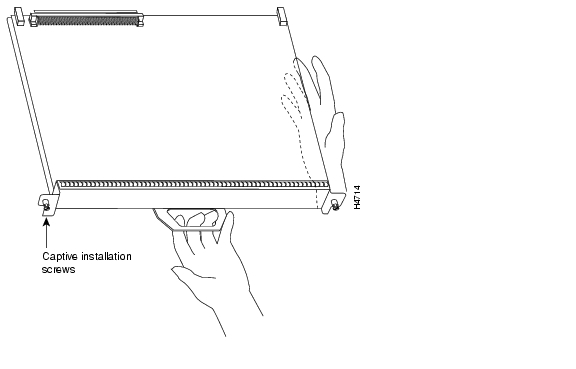
Figure 12 shows proper handling of an interface processor during installation.
Figure 12 Handling Interface Processors during Installation (Horizontal Orientation Shown)
This completes the procedure for removing and replacing an RSP2 in a Cisco 7507 or Cisco 7513 router.
Before you remove an interface processor that you will not replace, or replace an interface processor component, we recommend you shut down (disable) the interfaces to prevent anomalies when you reinstall the new or reconfigured interface processor. When you shut down an interface, it is designated administratively down in the show command displays. (For the interface shutdown procedure, see the "Upgrading Interface Processor Microcode Images" section.)
Use the following procedure to remove an interface processor:
Step 1
Step 2
Caution
Step 3
Step 4
Step 5
Step 6
Step 7
This completes the procedure for removing an interface processor.
Installing an Interface Processor
Interface processors slide into any available interface processor slot and connect directly to the backplane. The backplane slots are keyed so that interface processors can be installed only in interface processor slots. Interface processor fillers, which are blank interface processor carriers, occupy empty slots to maintain consistent air flow through the interface processor compartment.
If you install a new interface processor, you have to first remove the interface processor filler from the available interface processor slot. Figure 13 shows functional details of inserting an interface processor and using ejector levers. ( Figure 12 shows proper handling of an interface processor during installation.)
Note
Caution
Use the following procedure to install an interface processor:
Step 1
Step 2
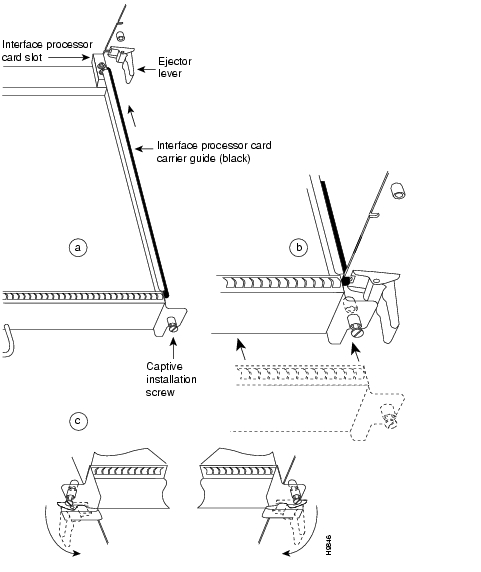
Step 3
Figure 13 Location of Ejector Levers and Captive Installation Screws
Step 4
Caution
Step 5
Step 6
Caution
Step 7
Step 8
Caution
This completes the procedure for installing an interface processor.
Connecting the Interface Processor Cables
For instructions on installing the cables, refer to your interface processor installation and configuration guide at: http://www.cisco.com/univercd/cc/td/doc/product/core/cis7505/interpro/index.htm.
Configuring the Interface Processor
For complete descriptions of interface subcommands and the configuration options available for your interface processor, refer to the configuration note for your interface processor and to the appropriate Cisco IOS software configuration publications. (See the "Related Documentation" section.)
Using the EXEC Command Interpreter
After you have connected your interface processor interface cables, but before you can use the interfaces, you must configure them using the configure command. However, before you can use the configure command, you must enter the privileged level of the EXEC command interpreter with the enable command. The system will prompt you for a password if one has been set; this applies to all interface processors. The system prompt for the privileged level ends with a pound sign (#) instead of an angle bracket (>).
At the console terminal, use the following procedure to enter the privileged level:
Step 1
Router> enablePassword:Step 2
Step 3
Router#This completes the procedure to enter the privileged level of the EXEC command interpreter.
Upgrading Interface Processor Microcode Images
Cisco 7000 series and Cisco 7500 series routers support downloadable microcode. Each interface processor requires a specific microcode image to operate, and each router is shipped with Cisco IOS software images and interface processor microcode images installed. Microcode images are bundled with the Cisco IOS software image that shipped with your router. We strongly recommend that you use these bundled microcode images.
You can download new microcode versions and store multiple versions in Flash memory, and you can boot from them just as you can with the system software images. System software upgrades might also contain upgraded microcode images, which will load automatically when the new software image is loaded.
You can download microcode to Flash memory by copying the Trivial File Transfer Protocol (TFTP) image of a microcode version to Flash memory. When the microcode image is stored in Flash memory, you can use the microcode reload command to manually load the new microcode file, and the configure command to instruct the system to load the new image automatically at each system boot.
Caution
To compare the size of the microcode image and the amount of Flash memory available, you must know the size of the new microcode image. The image size is specified in the README file that is included on the floppy disk with the new image. Note the size of the new image before proceeding, to ensure that you have sufficient available Flash memory for the new image.
Note
Use the following procedure to copy a microcode version from a TFTP server to Flash memory:
Step 1
Router# show flash4096K bytes of flash memory on embedded flash (in RSP1).file offset length name(additional displayed text omitted from this example)[4085336/4194304 bytes free]Step 2
buffer overflow - xxxx/xxxxwhere xxxx/xxxx is the number of bytes read in/number of bytes available.
Step 3
Router# copy tftp flashStep 4
IP address or name of remote host [255.255.255.255]? 1.1.1.106Step 5
Name of file to copy? vip221-40Step 6
Copy vip221-40 from 1.1.1.106 into flash memory? [confirm]If the correct file is not shown, enter no at the prompt to return to the system prompt; then enter the correct file name.
Step 7
Erase flash before writing? [confirm] noWhile the file is copied to Flash, output similar to the following is displayed:
Loading from 1.1.1.106:
!!!!!!!!!!!!!!!!!!!!!!!!!!!!!!!!!!!!!!!!!!!!!!!!!!!!
[OK - 108966/4194304 bytes] Verifying via checksum... Flash verification successful. Length = 53364, checksum = 0x0000Step 8
Router# show flash
4096K bytes of flash memory on embedded flash (in RSP1).
file offset length name 1 0xD0D4 53364 vip221-40 [4085336/4194304 bytes free]Step 9
Router# configure terminalEnter configuration commands, one per line. End with CNTL/Z.Router(config)#Step 10
Router(config)# microcode vip2 slot0:vip221-40Step 11
Step 12
Router# copy running-config startup-config[OK]Router#The microcode reload command is automatically added to your running configuration. The new interface processor microcode image will load automatically the next time the system boots or reinitializes.
Step 13
Router# configureRouter(config)# microcode reloadImmediately after you enter the microcode reload command and press Return, the system reloads all microcode. Configuration mode remains enabled; after the reload is complete, press Ctrl-Z to exit from Configuration mode and return to the system prompt.
Step 14
Router# show running-configThis completes the procedure for downloading microcode to Flash memory. For more information on downloading microcode, refer to the Upgrading Software and Microcode in Cisco 7000 Series Routers document at http://www.cisco.com/univercd/cc/td/doc/product/software/ssr921/7k_921cn/54755.htm. Also refer to the specific installation and configuration guide for your interface processor.
Troubleshooting
This section provides information on troubleshooting the interface processor. For further information, see the "Obtaining Technical Assistance" section.
•
If after configuring the interface processor, it is not recognized, you may be running an incorrect Cisco IOS version. For hardware/software compatibility, refer to the Software Advisor at: http://www.cisco.com/cgi-bin/Support/CompNav/Index.pl.
•
If you receive a "%RSP-3-RESTART: cbus complex" error message, refer to the following document for more information: http://www.cisco.com/warp/public/63/cbus_complex.html.
•
If you receive a "%RSP-3-RESTART: interface [xxx] output stuck/frozen/not transmitting Error Message", refer to the following document for more information: http://www.cisco.com/warp/public/63/output_stuck.shtml.
•
For more information on troubleshooting by technology, refer to the following URL: http://www.cisco.com/public/technotes/serv_tips.shtml.
Obtaining Documentation
The following sections explain how to obtain documentation from Cisco Systems.
World Wide Web
You can access the most current Cisco documentation on the World Wide Web at the following URL:
Translated documentation is available at the following URL:
http://www.cisco.com/public/countries_languages.shtml
Documentation CD-ROM
Cisco documentation and additional literature are available in a Cisco Documentation CD-ROM package, which is shipped with your product. The Documentation CD-ROM is updated monthly and may be more current than printed documentation. The CD-ROM package is available as a single unit or through an annual subscription.
Ordering Documentation
Cisco documentation is available in the following ways:
•
http://www.cisco.com/cgi-bin/order/order_root.pl
•
http://www.cisco.com/go/subscription
•
Documentation Feedback
If you are reading Cisco product documentation on Cisco.com, you can submit technical comments electronically. Click Leave Feedback at the bottom of the Cisco Documentation home page. After you complete the form, print it out and fax it to Cisco at 408 527-0730.
You can e-mail your comments to bug-doc@cisco.com.
To submit your comments by mail, use the response card behind the front cover of your document, or write to the following address:
Cisco Systems
Attn: Document Resource Connection
170 West Tasman Drive
San Jose, CA 95134-9883We appreciate your comments.
Obtaining Technical Assistance
Cisco provides Cisco.com as a starting point for all technical assistance. Customers and partners can obtain documentation, troubleshooting tips, and sample configurations from online tools by using the Cisco Technical Assistance Center (TAC) Web Site. Cisco.com registered users have complete access to the technical support resources on the Cisco TAC Web Site.
Cisco.com
Cisco.com is the foundation of a suite of interactive, networked services that provides immediate, open access to Cisco information, networking solutions, services, programs, and resources at any time, from anywhere in the world.
Cisco.com is a highly integrated Internet application and a powerful, easy-to-use tool that provides a broad range of features and services to help you to
•
•
•
•
•
You can self-register on Cisco.com to obtain customized information and service. To access Cisco.com, go to the following URL:
Technical Assistance Center
The Cisco TAC is available to all customers who need technical assistance with a Cisco product, technology, or solution. Two types of support are available through the Cisco TAC: the Cisco TAC Web Site and the Cisco TAC Escalation Center.
Inquiries to Cisco TAC are categorized according to the urgency of the issue:
•
•
•
•
Which Cisco TAC resource you choose is based on the priority of the problem and the conditions of service contracts, when applicable.
Cisco TAC Web Site
The Cisco TAC Web Site allows you to resolve P3 and P4 issues yourself, saving both cost and time. The site provides around-the-clock access to online tools, knowledge bases, and software. To access the Cisco TAC Web Site, go to the following URL:
All customers, partners, and resellers who have a valid Cisco services contract have complete access to the technical support resources on the Cisco TAC Web Site. The Cisco TAC Web Site requires a Cisco.com login ID and password. If you have a valid service contract but do not have a login ID or password, go to the following URL to register:
http://www.cisco.com/register/
If you cannot resolve your technical issues by using the Cisco TAC Web Site, and you are a Cisco.com registered user, you can open a case online by using the TAC Case Open tool at the following URL:
http://www.cisco.com/tac/caseopen
If you have Internet access, it is recommended that you open P3 and P4 cases through the Cisco TAC Web Site.
Cisco TAC Escalation Center
The Cisco TAC Escalation Center addresses issues that are classified as priority level 1 or priority level 2; these classifications are assigned when severe network degradation significantly impacts business operations. When you contact the TAC Escalation Center with a P1 or P2 problem, a Cisco TAC engineer will automatically open a case.
To obtain a directory of toll-free Cisco TAC telephone numbers for your country, go to the following URL:
http://www.cisco.com/warp/public/687/Directory/DirTAC.shtml
Before calling, please check with your network operations center to determine the level of Cisco support services to which your company is entitled; for example, SMARTnet, SMARTnet Onsite, or Network Supported Accounts (NSA). In addition, please have available your service agreement number and your product serial number.
![]()
![]()
![]()
![]()
![]()
![]()
![]()
![]()
Posted: Sun Feb 19 00:54:29 PST 2006
All contents are Copyright © 1992--2006 Cisco Systems, Inc. All rights reserved.
Important Notices and Privacy Statement.