|
|

Cisco 7010 Product Numbers: ACC-7010RMK= and ACC-7010CBLM= Cisco 7505 Product Numbers: ACS/5-RMK= and ACS/5-CBLM=
Customer Order Number: DOC-781231=
This document contains instructions for installing the Cisco 7010 and Cisco 7505 in an equipment rack using the rack-mount kit, and for installing the cable management brackets on the Cisco 7010 and Cisco 7505.
The rack-mount kit provides hardware for mounting the chassis in most standard 19-inch or Telco-type equipment racks. The cable management kit provides two brackets for routing and securing network interface cables at the interface processor end of the chassis.
Both kits are included with their respective chassis, and each kit is available as a spare part.
The sections in this document include the following:
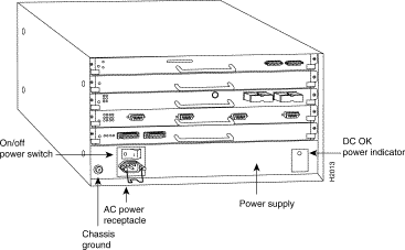
The Cisco 7010 is the five-slot model in the Cisco 7000 series product line and the Cisco 7505 is the five-slot model in the Cisco 7500 series. Figure 1 shows the interface processor end of the Cisco 7010 chassis.
The interface processor end of the chassis contains the processor slots, the AC power receptacle (a DC-input power supply is available, but not shown), the power switch, the DC OK status LED, and a screw for a chassis ground connection. The noninterface processor end of the chassis is a removable panel (secured with two captive slotted screws) that provides access to the internal components. For a complete description of the chassis, refer to the Cisco 7010 Hardware Installation and Maintenance or Cisco 7505 Hardware Installation and Maintenance publications.
You can mount the chassis in most standard 19-inch or Telco-type equipment racks, with either end of the chassis at the front of the rack. Ideally, you should be able to access both ends of the router without having to remove it from the rack. Because the interface processor end provides access to the power switch, processor slots, and all status LEDs, we recommend that you mount the router with the interface processor end at the front, or most accessible side, of the rack.
The rack-mount kit comprises two chassis ears that attach to the sides of the chassis at either the interface processor or noninterface processor end, four fasteners to secure the ears to the chassis, and eight fasteners to secure the ears to the mounting strips or posts on the equipment rack.
The cable management kit includes two brackets and fasteners to secure the brackets to the inner sides of the interface processor end of the chassis. By routing cables through the brackets and away from the interface ports, you can keep cables sorted and organized, provide strain relief for heavy or lengthy cables, and maintain clear access to interface processors and ports in the lower slots.
Before installing the rack-mounting hardware or the cable management brackets, read the safety guidelines and prerequisites in the following section, "Prerequisites."
The following sections provide safety guidelines that you should follow to avoid injuring yourself or damaging the equipment, a list of the tools and parts you need, and guidelines for rack-mounted equipment that will help you to avoid overtemperature conditions and maintain trouble-free operation.
Review the following guidelines to help ensure your safety and protect the equipment against damage during the installation.
When working with any electrical equipment, the following guidelines will help to ensure your safety and protect the equipment. This list is not inclusive of all potentially hazardous situations, so be alert.
In addition, use the guidelines that follow when working with any equipment that is connected to telephone wiring or other network cabling.
Whenever you lift the chassis or any heavy object, follow these guidelines:
This section lists the equipment you need to install the rack-mounting hardware and cable management brackets.
You need the following tools and parts to rack-mount the chassis:
You need the following tools and parts to install the cable management brackets:
Also, you might need another person to assist you with the installation. When installing the router in an enclosed rack, removing the door temporarily may provide additional clearance. We recommend that you have someone to assist you by supporting the chassis while you mount it in the rack by securing the chassis ears to the mounting strips on the rack posts.
The rack-mounting hardware included with the router is suitable for most 19-inch equipment racks or Telco-type racks. The chassis mounts to two posts or rails in the rack with two mounting ears, which attach to the sides of the chassis. Ideally, you should be able to access both ends of the router without having to remove it from the rack.
Before using a particular rack, check for obstructions (such as a power strip) that could impair access to the interface processors or chassis cover panel. As an alternative, you can install an equipment shelf in the rack, provided that the rack dimensions allow the router to be secured to the shelf and the overall configuration permits safe installation and access.
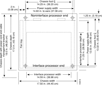
Figure 2 shows the chassis footprint and outer dimensions and the additional clearance required to remove or install components. All are representative of both the Cisco 7010 and Cisco 7505 chassis.
To use the rack-mounting hardware provided with the router, consider the following guidelines:
Planning a proper location for the router and the layout of your equipment rack is essential for successful system operation. Equipment placed too close together or inadequately ventilated can cause overtemperature conditions inside the chassis. When viewing the chassis from the interface processor end, the inlet air is drawn in through the right side of the chassis, and the exhaust air is forced out of the left side.
To help avoid overtemperature conditions, consider the following precautions when planning your rack installation:
The environmental monitoring functions provide status reports and warning messages about the internal chassis environment. For a description of the environmental monitor functions and related commands, refer to the Cisco 7010 Hardware Installation and Maintenance or Cisco 7505 Hardware Installation and Maintenance publications.
In addition to the preceding guidelines and precautions, follow these general precautions when planning your rack installation:
To mount the chassis in a rack, you will attach two ears to the sides of the chassis, then mount the ears to the rack-mounting strips or posts. The chassis is cantilevered off the ears. The chassis ears attach to either the front or back of the chassis, so that you can position either the interface processor or noninterface processor end at the front of the rack. In a four-post equipment rack with mounting strips in the rear posts, you can also mount the ears to the two rear posts; however, first ensure that the rear posts are free of obstacles such as structural supports or a power strip.
Figure 3 shows a typical 19-inch equipment rack with a power strip along one of the back posts.
If your rack has this feature, mount the interface processor end of the router away from the power strip to avoid problems accessing processor modules and cables. Also, if you will install the cable management brackets, ensure that the power strip will not block the sides of the brackets and prevent you from routing the cables through them. Install the cable management brackets after you install the chassis in the rack.

If you are installing a new router, mount the chassis in the rack before connecting any interface or power cables. Otherwise, disconnect all cables before moving the chassis. To help ensure that you connect the interface cables to their original interface ports, tag each cable with its slot/port address before you disconnect it.
Each chassis ear has two studs that fit into holes in the chassis. The chassis has two pairs of holes on each side: one pair near the interface processor end and one pair near the noninterface processor end. (See Figure 4.) Install both ears at the same end of the chassis (either at the interface processor end or the noninterface processor end), whichever will be in the front of the rack. For example, if you will install the chassis with the interface processor end of the router at the front and the noninterface processor end in the back of the rack, install the ears near the interface processor end of the chassis.
To install the ears on the chassis, follow these steps:
Step 1 Verify that you have all the parts you will need: two chassis ears, four M4 x 10-mm Phillips flathead screws, and eight 10-32 x 3/8-inch, slotted binderhead screws.
Step 2 On the rack, measure the space between the inner sides of the left and right front posts or mounting strips to ensure that it is at least 17.72 inches wide. (The chassis is 17.65 inches wide with the ears installed and must fit between the mounting strips.)
Step 3 Refer to Figure 4 and locate the guides in the chassis sides.
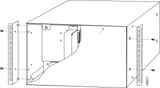
Step 4 While referring to Figure 4, turn the chassis so that the end that will be in the front of the rack is facing toward you. For example, Figure 4 shows the correct orientation for the router if the noninterface processor end will face out the front of the rack.
Step 5 On the sides of the chassis, locate the stud holes and tapped holes nearest you.
Step 6 Attach the first chassis ear to the right side of the chassis. Hold the ear in the orientation shown by the right ear in the Figure 4, with the studs pointing toward the chassis and the mounting strip facing you.
Step 7 Insert the studs into the holes on the side of the chassis, as shown in Figure 4.
Step 8 Use a number 2 Phillips screwdriver to secure two M4 x10-mm Phillips flathead screws to the chassis, then repeat this procedure for the other ear. Ensure that the strip of mounting holes on each ear is approximately flush with the end of the chassis. (See Figure 4.)
Step 9 Proceed to the next section to install the chassis in the rack.
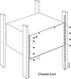
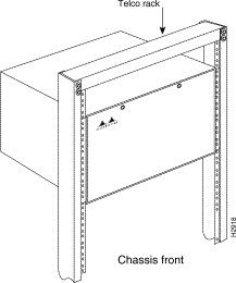
The ears secure the chassis to two rack posts, and the rest of the chassis is cantilevered off the ears. After installing the ears on the chassis, mount the chassis by securing the ears to two posts or mounting strips in the rack with the eight slotted screws provided. Because the ears bear the weight of the entire chassis, be sure to use all eight slotted screws to fasten the chassis ears to the rack posts. Figure 5 shows a typical installation in a standard, 19-inch equipment rack with four mounting posts. Figure 6 shows a typical installation in a Telco-type rack, which usually has two center posts and is bolted to the floor.
 | Warning To prevent personal injury, we recommend that two people install the chassis in the rack. (One person should support the chassis in the rack while the second person installs the fasteners.) |
| Warning Install heavier equipment near the bottom of the rack to maintain a low center of gravity. A top-heavy rack could easily tip over if it is not anchored or bolted to the floor, resulting in injury. |
To install the chassis in the rack, follow these steps:
Step 1 On the chassis, ensure that all captive screws (on the processor modules and on the access cover) are tightened.
Step 2 Make sure that your path to the rack is unobstructed. If the rack is on wheels, ensure that the brakes are engaged or that the rack is otherwise immobilized.
Step 3 If you are performing a first-time installation, proceed to the next step. Otherwise, disconnect the power cord and all interface cables before moving the chassis. If necessary, tag each interface cable with its current slot/port address so that you can easily reconnect it to that port after the chassis is installed in the rack.
| Warning Never attempt to lift or tilt the chassis with the handles on the interface processor carriers or with the cable management brackets. Neither the handles nor the brackets are designed to support the weight of the chassis. |
Step 4 Position the chassis so that the end with the ears attached is closest to you, then lift the chassis and move it to the rack. Avoid sudden twists or moves to prevent injury.
Step 5 Insert the rear of the chassis into the rack, pushing it back until the ears meet the front mounting strips or posts on both sides of the equipment rack.
Step 6 While keeping the chassis ears flush against the posts or mounting strips, slide the router up or down until the holes in the ears are aligned with those in the mounting strips.
Step 7 From the front of the rack, insert all eight 10-32 x 3/8-inch, slotted screws (four on each side) through the chassis ears and into the mounting strip.
Step 8 When all screws are inserted, use a 1/4-inch, flat-blade screwdriver to tighten each one.
Step 9 You can remove the four chassis feet to gain an extra 1/2-inch of vertical space below the chassis. However, we recommend that you allow at least 1 or 2 inches of vertical clearance above and below the chassis, which is greater than the height of the feet. If necessary, use a 1/4-inch, flat-blade screwdriver to remove the feet.
Step 10 If you are installing the router for the first time, proceed to the next section to install the cable management brackets.
To continue with the installation, refer to the Cisco 7010 Hardware Installation and Maintenance or Cisco 7505 Hardware Installation and Maintenance publications. Otherwise, if you disconnected the power and interface cables in Step 3, reconnect the power cord and network interface cables.
This completes the rack-mount installation.
The cable management brackets attach to the inner sides of the chassis at the interface processor end. (See Figure 7.)
Use the brackets to keep network interface cables untangled and orderly, provide strain relief, and prevent cables from hindering access to interface processors in the lower interface processor slots. Install the brackets before connecting network interface cables to the interface processor ports; otherwise, you will probably need to disconnect the cables to install the screws that secure the brackets. Route interface cables through the cable management brackets as you connect them to the interface processor ports. If necessary, wrap cable ties through the holes provided to secure small-gauge cables.

Follow these steps to install the two cable management brackets on the interface processor end of the chassis:
Step 1 Verify that you have all the parts you will need: two cable management brackets and six M3 x 8-mm, Phillips panhead screws.
Step 2 At the interface processor end of the chassis, place a bracket on an inner side of the chassis and align the three holes in the bracket with the holes in the chassis. (See Figure 7.)
Step 3 Insert and finger-tighten three M3 Phillips screws from the inner side of the chassis, through the bracket and into the chassis.
Step 4 When all three screws are inserted, use the number 1 Phillips screwdriver to tighten the screws.
Step 5 Repeat Steps 2 through 4 for the second bracket.
Step 6 When connecting network interface cables, route each cable through the brackets as shown in Figure 7. If you are using very thin cables that slip through the bracket openings, insert cable ties through the holes in the bracket and wrap them around the cables to secure them.
This completes the cable management bracket installation.
If you are installing a new system, proceed to the Cisco 7010 Hardware Installation and Maintenance or Cisco 7505 Hardware Installation and Maintenance publications for cabling guidelines and further instructions.
Cisco Information Online (CIO) is Cisco Systems' primary, real-time support channel. Maintenance customers and partners can self-register on CIO to obtain additional content and services.
Available 24 hours a day, 7 days a week, CIO provides a wealth of standard and value-added services to Cisco's customers and business partners. CIO services include product information, software updates, release notes, technical tips, the Bug Navigator, configuration notes, brochures, descriptions of service offerings, and download access to public and authorized files.
CIO serves a wide variety of users through two interfaces that are updated and enhanced simultaneously—a character-based version and a multimedia version that resides on the World Wide Web (WWW). The character-based CIO (called "CIO Classic") supports Zmodem, Kermit, Xmodem, FTP, Internet e-mail, and fax download options, and is excellent for quick access to information over lower bandwidths. The WWW version of CIO provides richly formatted documents with photographs, figures, graphics, and video, as well as hyperlinks to related information.
You can access CIO in the following ways:
http://www.cisco.com cio.cisco.com For a copy of CIO's Frequently Asked Questions (FAQ), contact cio-help@cisco.com. For additional information, contact cio-team@cisco.com.
tac@cisco.com. To obtain general information about Cisco Systems, Cisco products, or upgrades, contact 800 553-6387, 408 526-7208, or cs-rep@cisco.com.
![]()
![]()
![]()
![]()
![]()
![]()
![]()
![]()
Posted: Tue Dec 3 10:22:22 PST 2002
All contents are Copyright © 1992--2002 Cisco Systems, Inc. All rights reserved.
Important Notices and Privacy Statement.