|
|

Table Of Contents
Welcome Page of the Basic Setup Wizard
Configuring Client and Server Side VLANs
Configuring the Default Policy
Welcome Page of the Advanced Setup Wizard
How Do I Set Up a Virtual Server with Default Policy using Wizards?
How Do I Set Up a Virtual Server with Layer 7 Policy using Wizards?
How Do I Set Up a Virtual Server with Default Policy and Layer 7 Policies?
Configuring CVDM-CSM
CVDM-CSM allows user to setup the CSM module features with the help of wizards, which simplify the complex configuration.
This section includes the following topics:
•
FAQ
Understanding Wizards
CVDM-CSM Manager allows you to choose between two types of setup wizards: basic and advanced.
To choose between the two wizards:
Step 1
Step 2
Step 3
•
•
Step 4
Basic Setup Wizard
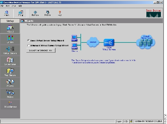
The Basic Setup Wizard allows you to configure and manage client and server VLANs and virtual servers, and associate Layer 4 policies. Figure 2-1 shows the Basic Setup Wizard page.
Figure 2-1 Basic Setup Wizard Page
Welcome Page of the Basic Setup Wizard
This wizard guides you to setup a virtual server with a default server farm and set of real servers. It also guides you to setup client-side or server side VLANs. You can also associate the VLAN to the Virtual Server.
The Welcome page lists the three basic configuration steps:
•
•
•
Configuring Client and Server Side VLANs
You can create client-side VLAN and server-side VLAN in route mode (different subnets) or bridge mode (single subnet), from this step. If you have configured at least one client-side or server-side VLAN, this step is optional.
In bridge mode configuration, the client-side and server-side VLANs are on the same subnets. Hence, the IP address and mask values of the client VLAN are populated for the server VLAN.
In route mode configuration, the client-side and server-side VLANs are on different subnets.
Select the radio button to configure in the Route mode or Bridge mode.
The fields in the table will vary according to the mode of configuration. In bridge mode configuration, you can configure only VLAN ID. The IP address and mask have to be the same for both client-side and server-side VLANs.
You can configure the following in the Configuring Client and Server Side VLANs dialog box.
VLAN ID
Specify the ID of the client-side VLAN. You can create a new VLAN or choose from a list of available VLANs.
Click
and select one of the following:
•
•
•
IP Address
Enter the IP address of the client-side VLAN. You can configure only one management IP address per VLAN.
Alias
Click
You can configure up to 255 aliases per VLAN. When more than one alias IP address is listed, they will appear serially, separated by a comma.
Gateways
Click
You can configure up to 7 gateways per VLAN, with a total of up to 255 gateways for the entire system.
A gateway must be in the same network as specified in the IP address. When more than one gateway IP address is listed, they will appear serially, separated by a comma.
Static Routes
Specify the static route. When more than one static route is listed, they will appear serially, separated by a comma.
Click
In bridge mode configuration, you can configure only VLAN ID. The IP address and mask have to be the same for both client-side and server-side VLANs.
VLAN ID
Specify the ID of the server-side VLAN. You can create a new VLAN or choose from a list of available VLANs.
Click
•
•
•
IP Address
(Disabled for bridge mode) Enter the IP address of the server-side VLAN. You can configure only one management IP address per VLAN.
Alias
(Only in route mode) Click
When more than one alias IP address is listed, they will appear serially, separated by a comma.
Mask
(Disabled for bridge mode) From the list, select the IP mask to be applied. You can choose from Class A, Class B, Class A and Class D masks.
If it is not specified, the default for network mask is 255.255.255.255.
Gateways
(Only in route mode) Click
You can configure up to seven gateways per VLAN, with a total of up to 255 gateways for the entire system. A gateway must be in the same network as specified in the IP address. When more than one gateway IP address is listed, they will appear serially, separated by a comma.
Static Routes
(Only in route mode) Specify the static route. When more than one static route is listed, they will appear serially, separated by a comma.
Click
Adding Static Routes
Step 1
Step 2
Step 3
•
•
Step 4
Step 5
Step 6
Configuring a Virtual Server
The Basic Setup Wizard allows you to configure the basic parameters of a virtual server. You can configure the IP address, mask, protocol, port, service type and also specify a VLAN to enable traffic from it.
The Advanced Setup Wizard allows you to configure client and server VLANs and also create layer 4 to layer 7 policies.
The Configure Virtual Server dialog box appears, displaying the following columns:
Configuring the Default Policy
From this step, you can configure multiple real servers and associate them to the server farm, and delete the association of the existing real server.
The following columns appear in the Configure Default Policy dialog box:
Note
From the Configure Default Policy dialog box, you can do the following:
•
–
–
–
•
•
Summary
You can see a list of all the generated CLI commands that are delivered to the device after you click the Finish button.
Step 1
Step 2
•
•
Step 3
Step 4
Step 5
If you selected Advanced Setup Wizard you will have to Configure Layer 7 Policies, then click Next.
Step 6
Step 7
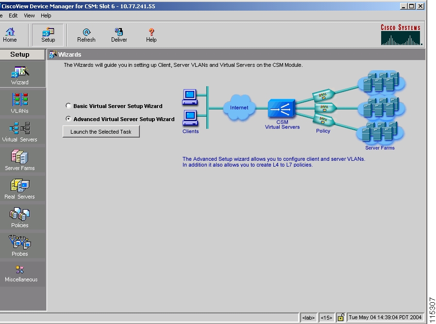
Advanced Setup Wizard
The Advanced Setup Wizard allows you to configure client and server VLANs and also create layer 4 to layer 7 policies. Figure 2-2 shows the Advanced Wizards page.
Figure 2-2 Advanced Wizards Page
Welcome Page of the Advanced Setup Wizard
This wizard guides you to setup a virtual server with a default server farm, set of real servers and create layer 4 to layer 7 policies. It also guides you to setup client-side or server side VLANs and associate a VLAN to virtual server.
The Welcome page lists the four configuration steps:
•
•
•
•
Configuring Layer 7 Policies
You can create and associate layer 7 policies to the virtual server. You can view the current policies, add new ones, delete existing ones, and also change the order of the policies.
You can configure the policy, and also configure and associate the following to the policy:
•
•
•
The Configure and Associate Layer 7 Policies dialog box appears. From this dialog box, you can do the following:
•
–
–
•
•
•
Note
FAQ
This section describes some common FAQs:
•
•
•
How Do I Set Up a Virtual Server with Default Policy using Wizards?
The Basic Setup Wizard allows you to configure and associate multiple real servers to the server farm and delete the association of the existing real server.
To setup a virtual server with the default policy:
Step 1
Step 2
Step 3
Step 4
Step 5
How Do I Set Up a Virtual Server with Layer 7 Policy using Wizards?
The Advanced Setup Wizard allows you to configure client and server VLANs and create layer 4 to layer 7 policies.
To setup a virtual server with Layer 7 policy:
Step 1
Step 2
Step 3
Step 4
Step 5
Step 6
How Do I Set Up a Virtual Server with Default Policy and Layer 7 Policies?
To set up a virtual server with default Policy and Layer 7 policies:
Step 1
•
Or
•
Step 2
Step 3
•
•
•
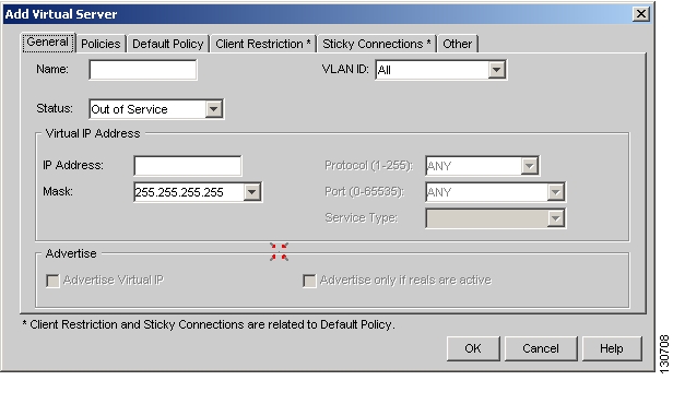
General
Click the General tab to configure the basic configuration details.
Figure 2-3 Add Virtual Server > General Dialog Box
The following columns appear:
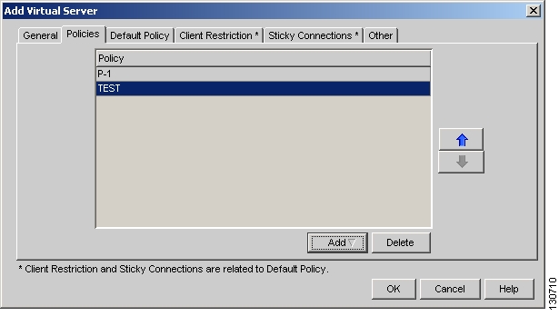
Policies
Click the Policies tab to add or delete policies.
Figure 2-4 Add Virtual Server > Policies Dialog Box
You have the following options:
•
–
–
•
•
•
Note
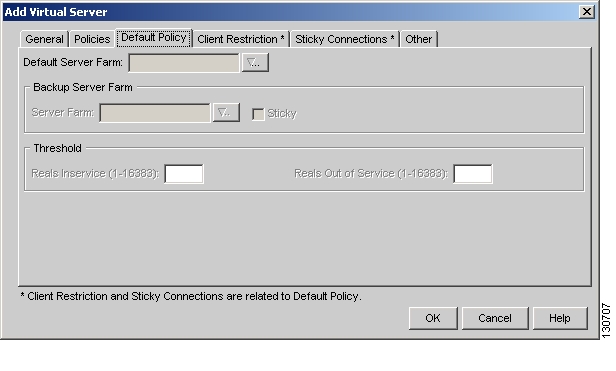
Default Policy
Click the Default Policy tab to add the default and backup server farms. You can configure a backup server farm to operate when a server farm is out of service.
To enable partial server farm failover, you can now define the threshold number of real servers to be out of service for the backup server farm to take over. You can also define the number of real servers to be in service for the server farm to be considered active.
Figure 2-5 Add Virtual Server > Default Policy Dialog Box
The following information appears:
Default Server Farm
Click
•
•
•
Server Farm
Click
•
•
•
Sticky
Select this check box to enable the sticky property.
This ensures that multiple connections from the same client, that match the same SLB policy stick (or attach) to the same real server.
Reals Inservice
The number of real servers to be in service for the server farm to be active.
Reals Out of Service
The number of real servers to be out of service for the backup server farm to take over.
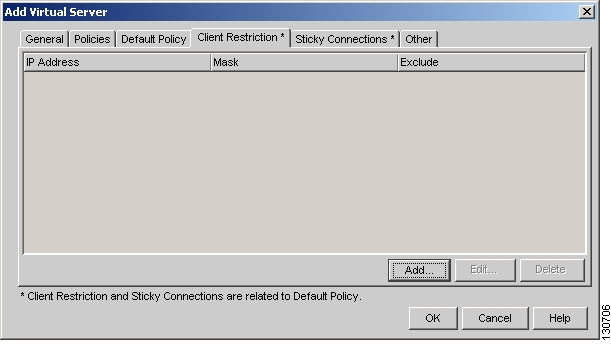
Client Restriction
Click the Client Restriction tab to add details of the clients restricted to use the virtual server.
Figure 2-6 Add Virtual Server > Client Restriction Dialog Box
You have the following options:
•
•
•
When you click Add or Edit, the following columns appear:
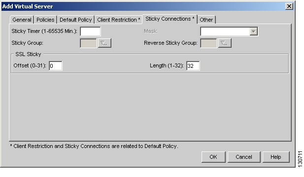
Sticky Connections
Sticky connections are connections from a client that conform to an SLB policy. Sticky connections use the same real server for subsequent connections. To ensure that the CVDM-CSM changes its connections to the opposite direction and sends them back to the source, you can configure a reverse sticky group.
Click the Sticky Connections tab to add details.
Figure 2-7 Add Virtual Server > Sticky Connections Dialog Box
The following information appears:
Sticky Timer
Specifies the period of time (in minutes) that the sticky information is kept.
Mask
From the list, select, Class A, Class B, Class A, and Class D masks.
If it is not specified, the default for network mask is 255.255.255.255.
Sticky Group
Click
•
•
•
Reverse Sticky Group
Click
•
•
•
You can stick an incoming SSL connection based only on the offset and length values of the SSL ID.
Offset
Enter the offset for the SSL ID.
Length
Enter the length of the SSL ID.
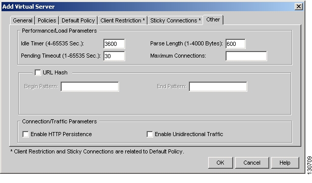
Other
Click the Other tab to configure performance, load, and traffic parameters. You can configure each virtual server with a pending connection timeout to terminate connections quickly if the switch becomes flooded with traffic.
Figure 2-8 Add Virtual Server > Other Dialog Box
The following information appears:
Idle Timer
Enter the idle connection timer duration in seconds.
Pending Timeout
Enter the time (in seconds) to wait before a connection is considered unreachable.
Parse Length
Enter the maximum number of bytes to parse for URLs and cookies.
Maximum Connections
Enter the maximum number of connections to the real server.
URL Hash
Select this check box to enable URL hash load-balancing algorithm.
You can enable the Begin Pattern and End Pattern fields only if you select this check box.
For more information on URL Hashing, see Configuring URL Hashing, page 4-15.
Begin Pattern
Specify the beginning pattern of the URL to parse.
End Pattern
Specify the ending pattern of the URL to parse.
Enable HTTP Persistence
Select this to enable or disable HTTP persistence for connections on the virtual server.
Enable Unidirectional Traffic
Select this to enable unidirectional traffic.
![]()
![]()
![]()
![]()
![]()
![]()
![]()
![]()
Posted: Fri Apr 15 04:35:24 PDT 2005
All contents are Copyright © 1992--2005 Cisco Systems, Inc. All rights reserved.
Important Notices and Privacy Statement.