|
|

Table Of Contents
DLP-A300 Clear a BLSR Span Lockout
DLP-A301 Initiate a BLSR Manual Ring Switch
DLP-A303 Initiate a BLSR Force Ring Switch
DLP-A309 View the Ethernet MAC Address Table
DLP-A310 View Ethernet Trunk Utilization
DLP-A311 Provision a Half Circuit Source and Destination on a BLSR or 1+1 Configuration
DLP-A312 Provision a Half Circuit Source and Destination on a Path Protection
DLP-A314 Assign a Name to a Port
DLP-A315 Log Out a User on a Single Node
DLP-A316 Log Out a User on Multiple Nodes
DLP-A320 View ML-Series Ether Ports PM Parameters
DLP-A321 View ML-Series POS Ports PM Parameters
DLP-A322 Manual or Force Switch the Node Timing Reference
DLP-A323 Clear a Manual or Force Switch on a Node Timing Reference
DLP-A324 Provision a VCAT Circuit Source and Destination
DLP-A325 Provision a VCAT Circuit Route
DLP-A326 Change a BLSR Node ID
DLP-A327 Configure the CTC Alerts Dialog Box for Automatic Popup
DLP-A328 Create a Two-Fiber BLSR Using the BLSR Wizard
DLP-A329 Create a Two-Fiber BLSR Manually
DLP-A330 Preprovision a Card Slot
DLP-A334 Delete Overhead Circuits
DLP-A337 Run the CTC Installation Wizard for Windows
DLP-A338 Run the CTC Installation Wizard for UNIX
DLP-A339 Delete a Node from the Current Session or Login Group
DLP-A340 View Port Status on the LCD
DLP-A341 Create an IP-Encapsulated Tunnel
DLP-A347 Refresh E-Series and G-Series Ethernet PM Counts
DLP-A348 Monitor PM Counts for a Selected Signal
DLP-A349 Clear Selected PM Counts
DLP-A350 View FC_MR-4 Statistics PM Parameters
DLP-A351 View FC_MR-4 Utilization PM Parameters
DLP-A352 View FC_MR-4 History PM Parameters
DLP-A353 Refresh FC_MR-4 PM Counts at a Different Time Interval
DLP-A356 TCC2/TCC2P Card Active/Standby Switch Test
DLP-A357 Create FC_MR-4 RMON Alarm Thresholds
DLP-A358 Delete FC_MR-4 RMON Alarm Thresholds
DLP-A359 Delete a Line DCC Termination
DLP-A362 Create a Four-Fiber BLSR Using the BLSR Wizard
DLP-A363 Create a Four-Fiber BLSR Manually
DLP-A364 Reset the TCC2/TCC2P Card Using CTC
DLP-A365 Initiate an Optical Protection Switch
DLP-A366 Initiate an Electrical Protection Switch
DLP-A367 Create a Provisionable Patchcord
DLP-A368 Delete a Provisionable Patchcord
DLP-A369 Provision an OC-N Circuit Route
DLP-A371 Remove Pass-through Connections
DLP-A372 Delete a Node from a Specified Login Node Group
DLP-A373 Install a MiniBNC EIA
DLP-A374 Change a Section DCC Termination
DLP-A375 Change a Line DCC Termination
DLP-A376 Change Line and Threshold Settings for the DS1/E1-56 Cards
DLP-A377 Provision Section DCC Terminations
DLP-A378 Provision Line DCC Terminations
DLP-A379 Change Line Transmission Settings for OC-N Cards
DLP-A380 Provision a Proxy Tunnel
DLP-A381 Provision a Firewall Tunnel
DLP-A382 Delete a Proxy Tunnel
DLP-A383 Delete a Firewall Tunnel
DLP-A384 Add a Member to a VCAT Circuit
DLP-A385 Delete a Member from a VCAT Circuit
DLP-A386 Install Electrical Cables on the UBIC-V EIAs
DLP-A387 Change Line and Threshold Settings for the DS3XM-12 Card
DLP-A388 Change Line and Threshold Settings for the DS3/EC1-48 Cards
DLP-A391 View CE-Series Ether Ports and POS Ports Statistics PM Parameters
DLP-A392 View CE-Series Ether Ports and POS Ports Utilization PM Parameters
DLP-A393 View CE-Series Ether Ports and POS Ports History PM Parameters
DLP-A394 View DS-N/SONET PM Parameters for the DS3XM-12 Card
DLP-A395 View BFDL PM Parameters for the DS3XM-12 Card
DLP-A397 Manually Route a Path Protection Circuit for a Topology Upgrade
DLP-A398 Automatically Route a Path Protection Circuit for a Topology Upgrade
DLPs A300 to A399
DLP-A300 Clear a BLSR Span Lockout
Step 1
From the View menu choose Go to Network View.
Step 2
Step 3
Tip
Step 4
Step 5
Step 6
Step 7
Step 8
DLP-A301 Initiate a BLSR Manual Ring Switch
Step 1
Step 2
Step 3
Tip
Step 4
Note
Step 5
Step 6
Step 7
Step 8
Step 9
DLP-A303 Initiate a BLSR Force Ring Switch
Caution
Caution
Step 1
Step 2
Step 3
Step 4
a.
Note
Note
b.
c.
On the network graphic, an F appears on the working BLSR channel where you invoked the protection switch. The span lines change color to reflect the forced traffic. Green span lines indicate the new BLSR path, and the lines between the protection switch are purple.
Performing a Force switch generates several conditions including FORCED-REQ-RING and WKSWPR.
Step 5
a.
Note
Note
b.
c.
On the network graphic, an F appears on the working BLSR channel where you invoked the protection switch. The span lines change color to reflect the forced traffic. Green span lines indicate the new BLSR path, and the lines between the protection switch are purple.
Performing a Force switch generates several conditions including FORCED-REQ-RING and WKSWPR.
Step 6
Step 7
DLP-A309 View the Ethernet MAC Address Table
Step 1
Step 2
Step 3
The MAC address table information appears.
Step 4
DLP-A310 View Ethernet Trunk Utilization
Step 1
Step 2
Step 3
The trunk utilization information for the current and previous time intervals appears.
Step 4
DLP-A311 Provision a Half Circuit Source and Destination on a BLSR or 1+1 Configuration
Note
Step 1
Step 2
Step 3
Step 4
Step 5
Step 6
Step 7
Step 8
Step 9
DLP-A312 Provision a Half Circuit Source and Destination on a Path Protection
Purpose
This task provisions a half circuit source and destination on path protectionconfigurations. A half circuit allows you to provision a partial path (one end of a circuit), for example, if you want to provision a circuit with the intent that the path will be completed at a later time or at a different location.
Tools/Equipment
None
Prerequisite Procedures
DLP-A60 Log into CTC, page 17-62
The Circuit Creation wizard Circuit Source page must be open.
Required/As Needed
As needed
Onsite/Remote
Onsite or remote
Security Level
Provisioning or higher
Step 1
Step 2
Step 3
Step 4
Step 5
Step 6
Step 7
Step 8
Step 9
Step 10
DLP-A313 Create a DCC Tunnel
Note
Step 1
Step 2
Step 3
•
•
–
–
Step 4
Step 5
•
•
•
•
–
–
–
–
DCC options do not appear if they are used by the ONS 15454 (DCC1) or other tunnels.
Step 6
Step 7
•
•
•
•
–
–
–
–
DCC options do not appear if they are used by the ONS 15454 (DCC1) or other tunnels.
Step 8
Step 9
Step 10
DLP-A314 Assign a Name to a Port
Step 1
Step 2
Step 3
Step 4
The port name can be up to 32 alphanumeric/special characters. The field is blank by default.
Step 5
Step 6
DLP-A315 Log Out a User on a Single Node
Purpose
This task logs out a user from a single node.
Tools/Equipment
None
Prerequisite Procedures
Required/As Needed
As needed
Onsite/Remote
Onsite or remote
Security Level
Superuser only
Step 1
Step 2
Step 3
Step 4
Step 5
Step 6
DLP-A316 Log Out a User on Multiple Nodes
Purpose
This task logs out a user from multiple nodes.
Tools/Equipment
None
Prerequisite Procedures
Required/As Needed
As needed
Onsite/Remote
Onsite or remote
Security Level
Superuser only
Step 1
Step 2
Step 3
Step 4
Step 5
Step 6
Step 7
Step 8
Step 9
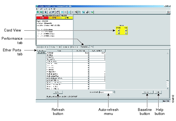
DLP-A320 View ML-Series Ether Ports PM Parameters
Note
Step 1
Step 2
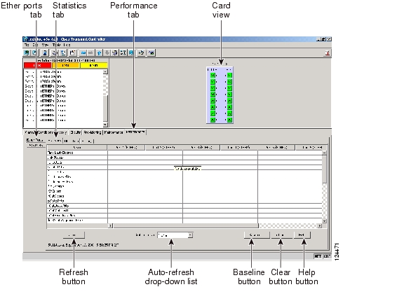
Figure 20-1 Ether Ports on the ML-Series Card View Performance Window
Step 3
Step 4
Note
Step 5
DLP-A321 View ML-Series POS Ports PM Parameters
Note
Step 1
Step 2
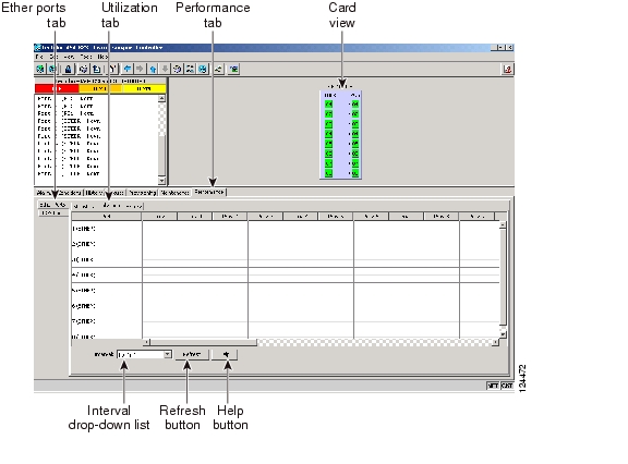
Figure 20-2 POS Ports on the ML-Series Card View Performance Window
Step 3
Step 4
Note
Step 5
DLP-A322 Manual or Force Switch the Node Timing Reference
Step 1
Step 2
Step 3
•
•
For information about the Clear option, see the "DLP-A323 Clear a Manual or Force Switch on a Node Timing Reference" task.
Step 4
Step 5
Step 6
Step 7
DLP-A323 Clear a Manual or Force Switch on a Node Timing Reference
Step 1
Step 2
Step 3
Step 4
Step 5
Step 6
Step 7
DLP-A324 Provision a VCAT Circuit Source and Destination
Purpose
This task provisions a virtual concatenated (VCAT) circuit source and destination.
Tools/Equipment
None
Prerequisite Procedures
DLP-A60 Log into CTC, page 17-62
The Circuit Creation wizard Circuit Source page must be open.
Required/As Needed
As needed
Onsite/Remote
Onsite or remote
Security Level
Provisioning or higher
Step 1
Step 2
Step 3
Step 4
Step 5
Step 6
Step 7
Step 8
Step 9
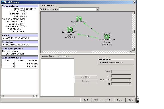
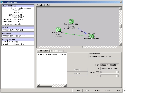
DLP-A325 Provision a VCAT Circuit Route
Purpose
This task provisions the circuit route for manually routed VCAT circuits.
Tools/Equipment
None
Prerequisite Procedures
DLP-A60 Log into CTC, page 17-62
The Circuit Creation wizard Route Review and Edit page must be open.
Required/As Needed
As needed
Onsite/Remote
Onsite or remote
Security Level
Provisioning or higher
Step 1
Step 2
Step 3
Figure 20-3 Manually Routing a VCAT Circuit
Step 4
Step 5
Step 6
Step 7
DLP-A326 Change a BLSR Node ID
Purpose
This task changes a BLSR node ID.
Tools/Equipment
None
Prerequisite Procedures
Required/As Needed
As needed
Onsite/Remote
Onsite or remote
Security Level
Provisioning or higher
Step 1
Step 2
Step 3
Step 4
Step 5
Step 6
DLP-A327 Configure the CTC Alerts Dialog Box for Automatic Popup
Step 1
Step 2
•
•
•
Step 3
Step 4
DLP-A328 Create a Two-Fiber BLSR Using the BLSR Wizard
Step 1
Step 2
Step 3
Step 4
•
•
Note
•
•
Step 5
If CTC determines that a BLSR cannot be created, for example, not enough optical cards are installed or it finds circuits with path protection selectors, a "Cannot Create BLSR" message appears. If this occurs, complete the following steps:
a.
b.
c.
d.
Step 6
Step 7
a.
b.
c.
d.
Note
Step 8
•
•
Note
Step 9
DLP-A329 Create a Two-Fiber BLSR Manually
Step 1
Step 2
Step 3
Step 4
•
•
•
•
•
The east and west ports must match the fiber connections and DCC terminations set up in the "A40 Provision BLSR Nodes" procedure.
•
Step 5
Note
Step 6
Step 7
Step 8
Step 9
•
•
Step 10
DLP-A330 Preprovision a Card Slot
Step 1
Step 2
When you preprovision a slot, the card appears purple in the CTC shelf graphic, rather than white when a card is installed in the slot. NP (not present) on the card graphic indicates that the card is not physically installed.
Step 3
DLP-A332 Change Tunnel Type
Step 1
Step 2
Step 3
Step 4
Step 5
Step 6
•
•
Step 7
Step 8
Step 9
Step 10
DLP-A333 Delete Circuits
Purpose
This task deletes circuits.
Tools/Equipment
None
Prerequisite Procedures
Required/As Needed
As needed
Onsite/Remote
Onsite or remote
Security Level
Provisioning or higher
Step 1
Step 2
Step 3
Step 4
a.
b.
Step 5
Step 6
Step 7
•
–
–
–
–
Note
•
Note
Step 8
•
•
Step 9
a.
b.
c.
Step 10
Step 11
Step 12
DLP-A334 Delete Overhead Circuits
Caution
Step 1
Step 2
Step 3
Step 4
Step 5
Step 6
DLP-A335 Delete VLANs
Purpose
This task removes VLANs from a domain.
Tools/Equipment
None
Prerequisite Procedures
See Chapter 6, "Create Circuits and VT Tunnels" for circuit creation procedures.
Required/As Needed
As needed
Onsite/Remote
Onsite or remote
Security Level
Provisioning or higher
Note
Step 1
Step 2
Step 3
Step 4
Step 5
Step 6
DLP-A336 Repair an IP Tunnel
Purpose
This task repairs circuits that have a OOS-PARTIAL status as a result of node IP address changes.
Tools/Equipment
None
Prerequisite Procedures
See Chapter 6, "Create Circuits and VT Tunnels" for circuit creation procedures.
Required/As Needed
As needed
Onsite/Remote
Onsite or remote
Security Level
Provisioning or higher
Step 1
Step 2
Step 3
Step 4
Step 5
•
•
•
Step 6
Step 7
Step 8
DLP-A337 Run the CTC Installation Wizard for Windows
Note
Note
Step 1
•
•
•
•
If your operating system is Windows NT 4.0, verify that Service Pack 6a or later is installed. From the Start menu, choose Programs > Administrative Tools > Windows NT Diagnostics and check the service pack on the Version tab of the Windows NT Diagnostics dialog box. If Service Pack 6a or later is not installed, do not continue. Install Service Pack 6a following the computer upgrade procedures for your site.
Note
Step 2
The Cisco Transport Controller Installation Wizard displays the components that will be installed on your computer:
•
•
•
•
Step 3
Step 4
•
•
Step 5
Step 6
•
•
–
–
Step 7
•
•
Step 8
Step 9
•
•
Step 10
Step 11
a.
•
•
Note
b.
c.
•
•
d.
e.
•
•
•
The drop-down list options for each program feature include:
•
•
•
To modify the directory where the JRE version is installed, click Change, navigate to the desired directory, and click OK.
f.
g.
Note
h.
i.
Step 12
Step 13
Step 14
DLP-A338 Run the CTC Installation Wizard for UNIX
Note
Note
Step 1
•
•
•
Note
Step 2
cd /cdrom/cdrom0/
Step 3
./setup.bat
The Cisco Transport Controller Installation Wizard displays the components that will be installed on your computer:
•
•
•
•
Step 4
Step 5
•
•
Step 6
Step 7
•
•
–
–
Step 8
•
•
Step 9
Step 10
•
•
Step 11
Step 12
a.
•
•
Note
b.
c.
•
•
d.
e.
•
•
•
The drop-down list options for each program feature include:
•
•
•
To modify the directory where the JRE version is installed, click Change, navigate to the desired directory, and click OK.
f.
g.
Note
h.
i.
Step 13
Step 14
Note
Step 15
DLP-A339 Delete a Node from the Current Session or Login Group
Purpose
This task removes a node from the current CTC session or login node group. To remove a node from a login node group that is not the current one, see the "DLP-A372 Delete a Node from a Specified Login Node Group" task.
Tools
None
Prerequisite Procedures
Required/As Needed
As needed
Onsite/Remote
Onsite or remote
Security Level
Provisioning or higher
Step 1
Step 2
Step 3
After a few seconds, the node disappears from the network view map.
Step 4
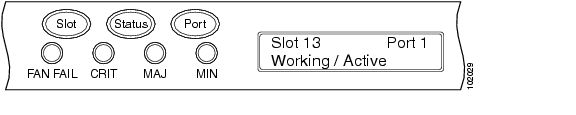
DLP-A340 View Port Status on the LCD
Step 1
Step 2
Step 3
Figure 20-4 shows an example of port status on the LCD panel.
Figure 20-4 Port Status on the LCD Panel
Note
Step 4
DLP-A341 Create an IP-Encapsulated Tunnel
Note
Step 1
Step 2
Step 3
Step 4
•
•
•
Step 5
Step 6
•
•
•
•
Step 7
Step 8
•
•
•
•
Step 9
Step 10
Step 11
DLP-A347 Refresh E-Series and G-Series Ethernet PM Counts
Step 1
Step 2
Step 3
•
•
•
•
Step 4
Step 5
Each monitored performance parameter has corresponding threshold values for the latest time period. If the value of the counter exceeds the threshold value for a particular selected interval, a threshold crossing alert (TCA) is raised. The number represents the counter value for each specific performance monitoring parameter.
Step 6
If a complete count over the selected interval is not possible, the value appears with a yellow background. For example, if you selected the 1-day interval, an incomplete or incorrect count can be caused by monitoring for less than 24 hours after the counter started, changing node timing settings, changing the time zone settings, replacing a card, resetting a card, or changing port service states. When the problem is corrected, the subsequent 1-day interval appears with a white background.
Step 7
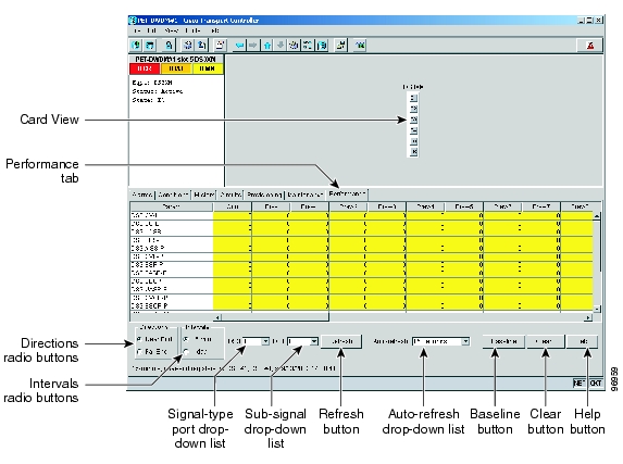
DLP-A348 Monitor PM Counts for a Selected Signal
Step 1
Step 2
Different port and signal-type menus appear depending on the card type and the circuit type. The appropriate types (DS1, DS3, VT path, STS path) appear based on the card. For example, the DS3XM cards list DS3, DS1, VT path, and STS path PM parameters as signal types. This enables you to select both the DS-3 port and the DS-1 within the specified DS-3.
Step 3
•
•
•
Figure 20-5 shows the port and signal type drop-down lists on the Performance window for a DS3XM-6 card.
Figure 20-5 Signal Type Drop-Down Lists for a DS3XM-6 Card
Step 4
Step 5
Step 6
DLP-A349 Clear Selected PM Counts
Caution
Step 1
Step 2
Step 3
Step 4
•
•
•
Step 5
Step 6
Step 7
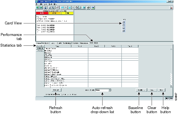
DLP-A350 View FC_MR-4 Statistics PM Parameters
Step 1
Step 2
Figure 20-6 FC_MR-4 Statistics on the Card View Performance Window
Step 3
Step 4
Step 5
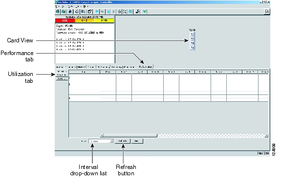
DLP-A351 View FC_MR-4 Utilization PM Parameters
Step 1
Step 2
Figure 20-7 FC_MR-4 Utilization on the Card View Performance Window
Step 3
Step 4
Step 5
Step 6
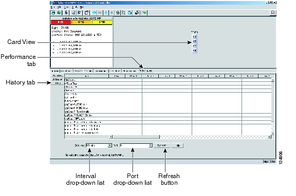
DLP-A352 View FC_MR-4 History PM Parameters
Step 1
Step 2
Figure 20-8 FC_MR-4 History on the Card View Performance Window
Step 3
Step 4
Step 5
DLP-A353 Refresh FC_MR-4 PM Counts at a Different Time Interval
Step 1
Step 2
Step 3
Step 4
•
•
•
•
Step 5
Step 6
DLP-A356 TCC2/TCC2P Card Active/Standby Switch Test
Step 1
Step 2
a.
b.
Step 3
Step 4
Step 5
Step 6
Step 7
Step 8
•
•
Step 9
Step 10
Step 11
Step 12
DLP-A357 Create FC_MR-4 RMON Alarm Thresholds
Purpose
This task sets up remote monitoring (RMON) to allow network management systems to monitor FC_MR-4 ports.
Tools/Equipment
None
Prerequisite Procedures
DLP-A60 Log into CTC, page 17-62 at the node where you want to set up RMON
Required/As Needed
As needed
Onsite/Remote
Onsite or remote
Security Level
Provisioning or higher
Note
Step 1
Step 2
Step 3
Step 4
Step 5
Step 6
Table 20-2 lists the enhanced mode MIBs available.
Step 7
Step 8
Step 9
Step 10
For a rising type of alarm, the measured value must move from below the falling threshold to above the rising threshold. For example, if a network is running below a rising threshold of 1000 collisions every 15 minutes and a problem causes 1001 collisions in 15 minutes, the excess occurrences trigger an alarm.
Step 11
A falling threshold is the counterpart to a rising threshold. When the number of occurrences is above the rising threshold and then drops below a falling threshold, it resets the rising threshold. For example, when the network problem that caused 1001 collisions in 15 minutes subsides and creates only 799 collisions in 15 minutes, occurrences fall below a falling threshold of 800 collisions. This resets the rising threshold so that if network collisions again spike over a 1000 per 15-minute period, an event again triggers when the rising threshold is crossed. An event is triggered only the first time a rising threshold is exceeded (otherwise, a single network problem might cause a rising threshold to be exceeded multiple times and cause a flood of events).
Step 12
Step 13
DLP-A358 Delete FC_MR-4 RMON Alarm Thresholds
Purpose
This task deletes RMON threshold crossing alarms for FC_MR-4 ports.
Tools/Equipment
None
Prerequisite Procedures
A357 Create FC_MR-4 RMON Alarm Thresholds
Required/As Needed
As needed
Onsite/Remote
Onsite or remote
Security Level
Provisioning or higher
Step 1
Step 2
Step 3
Step 4
Step 5
Step 6
DLP-A359 Delete a Line DCC Termination
Caution
Step 1
Step 2
Step 3
Step 4
DLP-A362 Create a Four-Fiber BLSR Using the BLSR Wizard
Step 1
Step 2
Step 3
Step 4
•
•
•
•
•
Step 5
If CTC determines that a BLSR cannot be created, for example, not enough optical cards are installed or it finds circuits with path protection selectors, a "Cannot Create BLSR" message appears. If this occurs, complete the following steps:
a.
b.
c.
d.
Step 6
Step 7
Step 8
a.
b.
c.
d.
Note
Step 9
•
•
Note
Step 10
DLP-A363 Create a Four-Fiber BLSR Manually
Step 1
Step 2
Step 3
Step 4
•
•
•
•
•
The east and west ports must match the fiber connections and DCC terminations set up in the "A40 Provision BLSR Nodes" procedure.
•
•
•
•
Step 5
Note
Step 6
Step 7
Step 8
Step 9
•
•
Step 10
DLP-A364 Reset the TCC2/TCC2P Card Using CTC
Warning
Note
Note
Step 1
Step 2
Step 3
Step 4
Step 5
Note
Step 6
Step 7
DLP-A365 Initiate an Optical Protection Switch
Step 1
Step 2
Step 3
Step 4
If you choose a Manual switch, the command will switch traffic only if the path has an error rate less than the signal degrade bit error rate threshold. A Force switch will switch traffic even if the path has SD or SF conditions; however, a Force switch will not override an SF on a 1+1 protection channel A Force switch has a higher priority than a Manual switch.
Step 5
Step 6
DLP-A366 Initiate an Electrical Protection Switch
Note
Step 1
Step 2
Step 3
Step 4
Step 5
Step 6
DLP-A367 Create a Provisionable Patchcord
Note
Note
Note
Note
Step 1
Step 2
Step 3
a.
b.
c.
Step 4
a.
b.
c.
Step 5
a.
b.
c.
d.
Step 6
Step 7
Step 8
DLP-A368 Delete a Provisionable Patchcord
Purpose
This task deletes a provisionable patchcord.
Tools/Equipment
None
Prerequisite Procedures
Required/As Needed
As needed
Onsite/Remote
Onsite or remote
Security Level
Provisioning and higher
Note
Step 1
Step 2
Step 3
Step 4
Step 5
DLP-A369 Provision an OC-N Circuit Route
Purpose
This task provisions the circuit route for manually routed OC-N circuits.
Tools/Equipment
None
Prerequisite Procedures
DLP-A60 Log into CTC, page 17-62
The Circuit Creation wizard, Route Review/Edit area, must be open.
Required/As Needed
As needed
Onsite/Remote
Onsite or remote
Security Level
Provisioning or higher
Step 1
Step 2
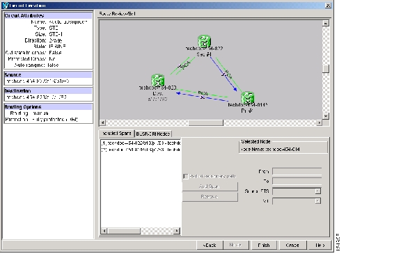
The arrow turns yellow. In the Selected Span area, the From and To fields provide span information. The source STS appears. Figure 20-9 shows an example of a manually routed circuit.
Figure 20-9 Manually Routing an OC-N Circuit
Step 3
Note
Step 4
Step 5
•
•
•
Figure 20-10 Manually Routing a BLSR DRI Circuit Route
Step 6
DLP-A371 Remove Pass-through Connections
Step 1
Step 2
Step 3
Step 4
Step 5
Step 6
Step 7
Step 8
Step 9
Step 10
Note
Step 11
Step 12
Step 13
DLP-A372 Delete a Node from a Specified Login Node Group
Purpose
This task removes a node from a specified login node group. To remove a node from the current login node group, see the "DLP-A339 Delete a Node from the Current Session or Login Group" task.
Tools
None
Prerequisite Procedures
Required/As Needed
As needed
Onsite/Remote
Onsite or remote
Security Level
Provisioning or higher
Step 1
Step 2
Step 3
Step 4
Step 5
Step 6
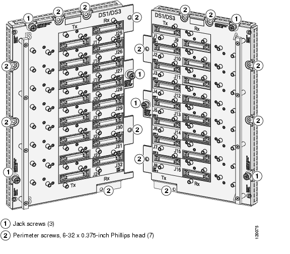
DLP-A373 Install a MiniBNC EIA
Caution
Note
Note
Step 1
Step 2
Step 3
Step 4
Caution
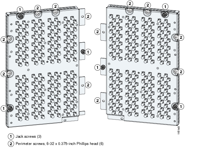
Step 5
Caution
Figure 20-11 MiniBNC EIA Screw Locations
Figure 20-12 MiniBNC EIA Jack Screw
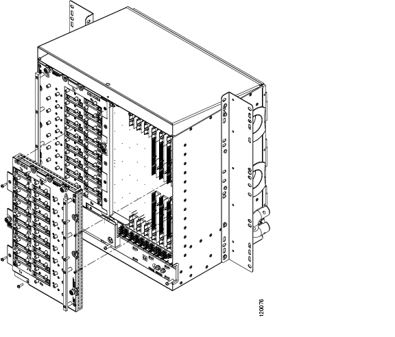
Step 6
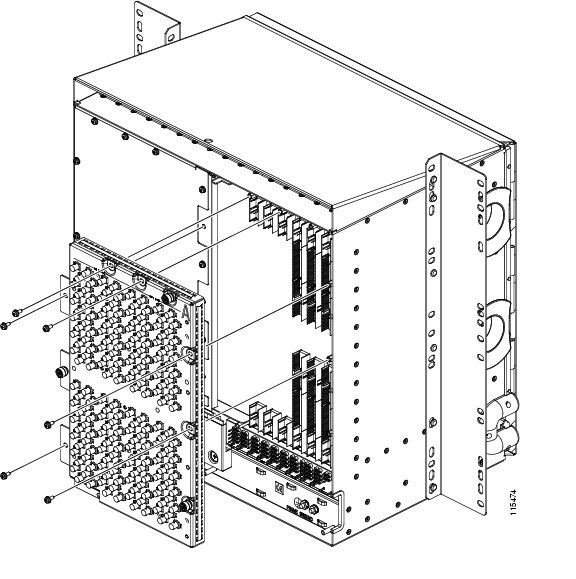
Figure 20-13 shows a MiniBNC EIA installation.
Figure 20-13 Installing the MiniBNC EIA
Step 7
DLP-A374 Change a Section DCC Termination
Step 1
Step 2
Step 3
Step 4
•
•
•
Step 5
Step 6
DLP-A375 Change a Line DCC Termination
Step 1
Step 2
Step 3
Step 4
•
•
•
Step 5
Step 6
DLP-A376 Change Line and Threshold Settings for the DS1/E1-56 Cards
Note
Step 1
Step 2
Step 3
Note
Note
Step 4
Step 5
Step 6
For definitions of the line settings, see Table 20-3. For definitions of the line threshold settings, see Table 20-4. For definitions of the electrical path threshold settings, see Table 20-5. For definitions of the SONET threshold settings, see Table 20-6. For definitions of the card settings, see Table 20-7.
Table 20-3 describes the values on the Provisioning > Line tabs for the DS1/E1-56 cards.
Table 20-4 describes the values on the Provisioning > Line Thresholds tabs for the DS1/E1-56 card.
Table 20-5 describes the values on the Provisioning > Elect Path Thresholds tabs for the DS1/E1-56 card.
Table 20-6 describes the values on the Provisioning > SONET Thresholds tabs for the DS1/E1-56 card.
Table 20-7 describes the values on the Provisioning > Card tabs for the DS1/E1-56 card.
Note
Step 7
DLP-A377 Provision Section DCC Terminations
Caution
Note
Step 1
Step 2
Step 3
Note
Step 4
Step 5
Step 6
Step 7
•
•
•
Note
Step 8
a.
b.
–
–
–
–
–
c.
–
AITS—(Default) Acknowledged Information Transfer Service. Does not exchange data until a logical connection between two LAP-D users is established. This service provides reliable data transfer, flow control, and error control mechanisms.
UITS—Unacknowledged Information Transfer Service. Transfers frames containing user data with no acknowledgement. The service does not guarantee that the data presented by one user will be delivered to another user, nor does it inform the user if the delivery attempt fails. It does not provide any flow control or error control mechanisms.
–
–
–
–
Step 9
Note
Step 10
DLP-A378 Provision Line DCC Terminations
Note
Step 1
Step 2
Step 3
Note
Step 4
Step 5
Step 6
Step 7
•
•
Note
Step 8
a.
b.
–
–
–
–
–
Step 9
Note
Step 10
DLP-A379 Change Line Transmission Settings for OC-N Cards
Note
Step 1
Step 2
Note
Step 3
Step 4
Step 5
Step 6
DLP-A380 Provision a Proxy Tunnel
Purpose
This task sets up a proxy tunnel to communicate with a non-ONS far-end node. Proxy tunnels are only necessary when the proxy server is enabled and a foreign DCC termination exists, or if static routes exist so that the DCC network is used to access remote networks or devices. You can provision a maximum of 12 proxy server tunnels.
Tools/Equipment
None
Prerequisite Procedures
DLP-A60 Log into CTC, page 17-62
Required/As Needed
As needed
Onsite/Remote
Onsite or remote
Security Level
Superuser only
Note
Step 1
Step 2
Step 3
•
•
•
•
Step 4
Step 5
DLP-A381 Provision a Firewall Tunnel
Purpose
This task provisions destinations that will not be blocked by the firewall. Firewall tunnels are only necessary when the proxy server is enabled and a foreign DCC termination exists, or if static routes exist so that the DCC network is used to access remote networks or devices. You can provision a maximum of 12 firewall tunnels.
Tools/Equipment
None
Prerequisite Procedures
DLP-A60 Log into CTC, page 17-62
Required/As Needed
As needed
Onsite/Remote
Onsite or remote
Security Level
Superuser only
Note
Step 1
Step 2
Step 3
•
•
•
•
Step 4
Step 5
DLP-A382 Delete a Proxy Tunnel
Purpose
This task removes a proxy tunnel.
Tools/Equipment
None
Prerequisite Procedures
Required/As Needed
As needed
Onsite/Remote
Onsite or remote
Security Level
Superuser only
Step 1
Step 2
Step 3
Step 4
DLP-A383 Delete a Firewall Tunnel
Purpose
This task removes a firewall tunnel.
Tools/Equipment
None
Prerequisite Procedures
Required/As Needed
As needed
Onsite/Remote
Onsite or remote
Security Level
Superuser only
Step 1
Step 2
Step 3
Step 4
DLP-A384 Add a Member to a VCAT Circuit
Purpose
This task adds a member to one of the following VCAT circuits:
•
•
Adding a member to a VCAT circuit changes the size of the circuit. The new members use the VCAT member source, destination, and routing preference (common fiber or split routing) specified during the VCAT circuit creation procedure.
Tools/Equipment
FC_MR-4 card (enhanced mode) or CE-Series card.
Prerequisite Procedures
DLP-A60 Log into CTC, page 17-62
VCAT circuits must exist on the network. See the "NTP-A264 Create an Automatically Routed VCAT Circuit" procedure on page 6-82 or the "NTP-A265 Create a Manually Routed VCAT Circuit" procedure on page 6-87.
Required/As Needed
As needed
Onsite/Remote
Onsite or remote
Security Level
Provisioning or higher
Note
Note
Note
Note
Step 1
Step 2
Step 3
Step 4
a.
b.
c.
d.
Cross-connects of all In Group non-LCAS members must be in the same service state. If all existing members are in the Out of Group VCAT state, which for non-LCAS members is the OOS-MA,DSBLD service state, you can choose any service state for the new member.
e.
Step 5
Step 6
•
•
•
•
–
–
–
–
–
For additional information about circuit service states, refer to the "Circuits and Tunnels" chapter in the Cisco ONS 15454 Reference Manual.
Step 7
Step 8
Step 9
Note
•
•
•
–
–
–
–
•
Step 10
•
–
–
–
–
•
Step 11
a.
b.
c.
d.
e.
f.
•
•
•
g.
Step 12
a.
b.
c.
Step 13
Note
Step 14
a.
b.
Step 15
DLP-A385 Delete a Member from a VCAT Circuit
Purpose
This task removes a member from a VCAT circuit that was created with one of the following criteria:
•
•
This task reduces the size of the VCAT circuit.
Tools/Equipment
FC_MR-4 card (enhanced mode) or CE-Series card.
Prerequisite Procedures
DLP-A60 Log into CTC, page 17-62
VCAT circuits must exist on the network. See the "NTP-A264 Create an Automatically Routed VCAT Circuit" procedure on page 6-82 or the "NTP-A265 Create a Manually Routed VCAT Circuit" procedure on page 6-87.
As necessary, complete the "DLP-A437 Change a VCAT Member Service State" task on page 21-15 to change a SW-LCAS or LCAS member state to OOS-MA,OOG.
Required/As Needed
As needed
Onsite/Remote
Onsite or remote
Security Level
Provisioning or higher
Note
Note
Note
Step 1
Step 2
Step 3
Step 4
Step 5
Step 6
Step 7
DLP-A386 Install Electrical Cables on the UBIC-V EIAs
Note
Step 1
Figure 20-14 shows the UBIC-V slot designations.
Figure 20-14 UBIC-V Slot Designations
Step 2
Step 3
Step 4
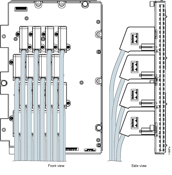
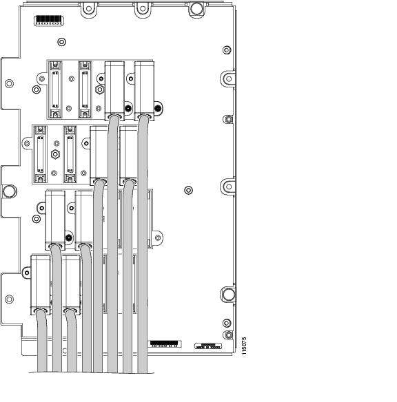
Figure 20-15 shows a UBIC-V with cables installed in all connectors.
Figure 20-15 Fully Cabled UBIC-V; Front- and Side-View
Figure 20-16 shows a partially populated UBIC-V.
Figure 20-16 Partially Cabled UBIC-V
Step 5
Note
Step 6
DLP-A387 Change Line and Threshold Settings for the DS3XM-12 Card
Note
Note
Step 1
Step 2
Step 3
Note
Note
Step 4
Step 5
Step 6
Step 7
Table 20-9 describes the values on the Provisioning > Line tabs for the DS3XM-12 cards.
Table 20-10 describes the values on the Provisioning > DS1 tabs for the DS3XM-12 cards. Refer to the Cisco ONS 15454 Reference Manual for more information about "portless" protection on DS3XM-12 cards.
Table 20-11 lists the line thresholds options for DS3XM-12 cards.
Table 20-12 describes the values on the Provisioning > Elect Path Thresholds tabs for the DS3XM-12 cards.
Table 20-13 describes the values on the Provisioning > SONET Thresholds tabs for the DS3XM-12 cards.
Note
Step 8
DLP-A388 Change Line and Threshold Settings for the DS3/EC1-48 Cards
Note
Step 1
Step 2
Step 3
Note
Note
Step 4
Step 5
Step 6
For definitions of the line settings, see Table 20-14. For definitions of the line threshold settings, see Table 20-15. For definitions of the electrical path threshold settings, see Table 20-16. For definitions of the SONET threshold settings, see Table 20-17.
Table 20-15 describes the values on the Provisioning > Line Thresholds tabs for the DS3/EC1-48 card.
Table 20-16 describes the values on the Provisioning > Elect Path Thresholds tabs for the DS3/EC1-48 card.
Table 20-17 describes the values on the Provisioning > SONET Thresholds tabs for the DS3/EC1-48 card.
Note
Step 7
DLP-A390 View Alarms
Step 1
Table 20-19 lists the color codes for alarm and condition severities.
Step 2
Step 3
DLP-A391 View CE-Series Ether Ports and POS Ports Statistics PM Parameters
Step 1
Step 2
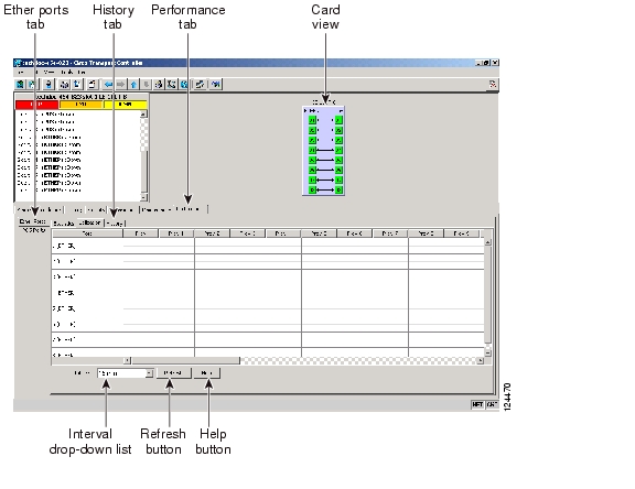
Figure 20-17 Ether Ports Statistics on the CE-Series Card View Performance Window
Step 3
Step 4
Note
Step 5
DLP-A392 View CE-Series Ether Ports and POS Ports Utilization PM Parameters
Step 1
Step 2
Figure 20-18 Ether Ports Utilization on the CE-Series Card View Performance Window
Step 3
Step 4
Step 5
Note
Step 6
DLP-A393 View CE-Series Ether Ports and POS Ports History PM Parameters
Step 1
Step 2
Figure 20-19 Ether Ports History on the CE-Series Card View Performance Window
Step 3
Step 4
Note
Step 5
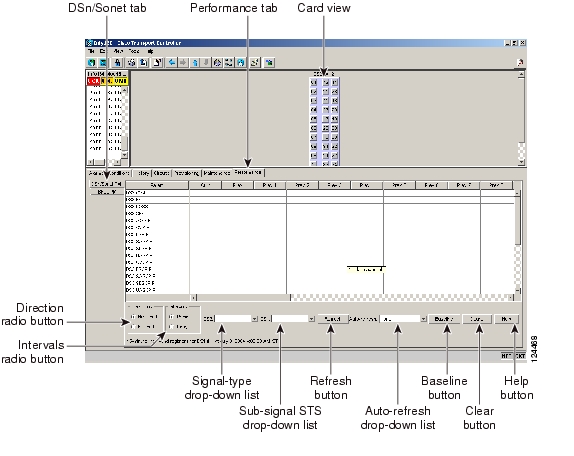
DLP-A394 View DS-N/SONET PM Parameters for the DS3XM-12 Card
Purpose
This task enables you to view DS-N/SONET PM parameters for near-end or far-end performance during selected time intervals on an DS3XM-12 electrical card and port to detect possible performance problems.
Tools/Equipment
None
Prerequisite Procedures
Before you monitor performance, be sure you have created the appropriate circuits and provisioned the card according to your specifications. For more information, see Chapter 6, "Create Circuits and VT Tunnels" and Chapter 10, "Change Card Settings."
Required/As Needed
As needed
Onsite/Remote
Onsite or remote
Security Level
Retrieve or higher
Step 1
Step 2
Figure 20-20 Viewing DS3XM-12 Card DSn/SONET Performance Monitoring Information
Note
Step 3
Step 4
Step 5
Note
Step 6
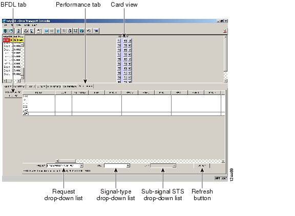
DLP-A395 View BFDL PM Parameters for the DS3XM-12 Card
Purpose
This task enables you to view bidirectional fiber data link (BFDL) PM parameters for near-end or far-end performance during selected time intervals on an DS3XM-12 electrical card and port to detect possible performance problems.
Tools/Equipment
None
Prerequisite Procedures
Before you monitor performance, be sure you have created the appropriate circuits and provisioned the card according to your specifications. For more information, see Chapter 6, "Create Circuits and VT Tunnels" and Chapter 10, "Change Card Settings."
Required/As Needed
As needed
Onsite/Remote
Onsite or remote
Security Level
Retrieve or higher
Step 1
Step 2
Figure 20-21 Viewing DS3XM-12 Card BFDL Performance Monitoring Information
Note
Step 3
•
•
•
•
•
Step 4
Step 5
Step 6
To refresh, reset, or clear PM counts, see the "NTP-A253 Change the PM Display" procedure on page 9-2.
Step 7
DLP-A397 Manually Route a Path Protection Circuit for a Topology Upgrade
Purpose
This task creates a manually routed USPR circuit during a conversion from an unprotected point-to-point or linear ADM system to a path protection.
Tools/Equipment
None
Prerequisite Procedures
DLP-A60 Log into CTC, page 17-62
NTP-A342 Convert a Point-to-Point or Linear ADM to a Path Protection Automatically, page 13-10
Required/As Needed
As needed
Onsite/Remote
Onsite or remote
Security Level
Provisioning or higher
Step 1
Step 2
Step 3
Step 4
DLP-A398 Automatically Route a Path Protection Circuit for a Topology Upgrade
Purpose
This task creates an automatically routed USPR circuit during a conversion from an unprotected point-to-point or linear ADM system to a path protection.
Tools/Equipment
None
Prerequisite Procedures
DLP-A60 Log into CTC, page 17-62
NTP-A342 Convert a Point-to-Point or Linear ADM to a Path Protection Automatically, page 13-10
Required/As Needed
As needed
Onsite/Remote
Onsite or remote
Security Level
Provisioning or higher
Note
Step 1
Step 2
•
•
Step 3
•
•
•
Step 4
a.
b.
•
•
•
Step 5
a.
b.
c.
Step 6
Step 7
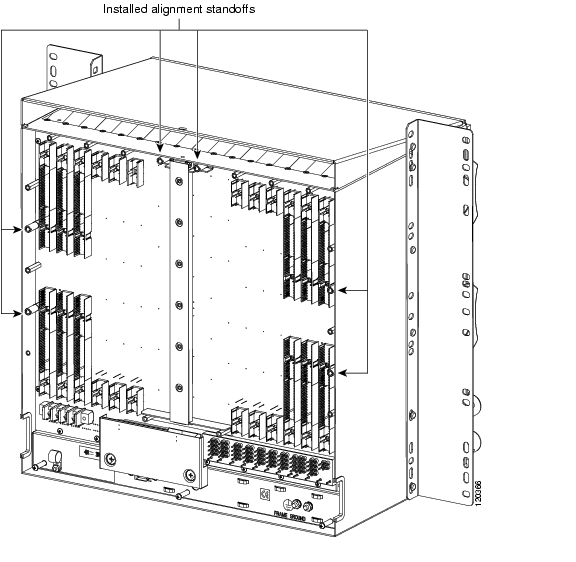
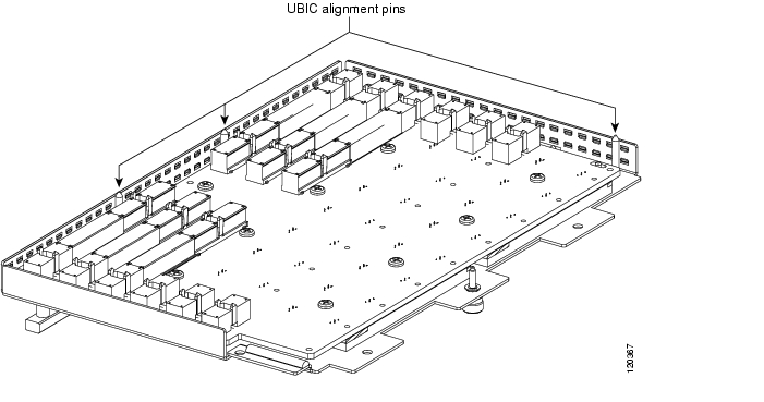
DLP-A399 Install a UBIC-H EIA
Caution
Note
Note
Step 1
Step 2
Step 3
Step 4
Step 5
Figure 20-22 Installed Alignment Standoffs
Step 6
Figure 20-23 UBIC-H Alignment Pins
Caution
Step 7
Caution
Figure 20-24 UBIC-H EIA Screw Locations
Figure 20-25 UBIC-H EIA Jack Screw
Step 8
Figure 20-26 Installing the UBIC-H EIA
Step 9
Step 10
![]()
![]()
![]()
![]()
![]()
![]()
![]()
![]()
Posted: Mon Nov 12 00:56:02 PST 2007
All contents are Copyright © 1992--2007 Cisco Systems, Inc. All rights reserved.
Important Notices and Privacy Statement.