|
|

Table Of Contents
NTP-A195 Document Card, Node, and Network Provisioning
NTP-A196 View Alarms, History, Events, and Conditions
NTP-A68 Delete Cleared Alarms from Display
NTP-A69 View Alarm-Affected Circuits
NTP-A70 View Alarm Counts on the LCD for a Node, Slot, or Port
NTP-A71 Create, Download, and Assign Alarm Severity Profiles
NTP-A168 Enable, Modify, or Disable Alarm Severity Filtering
NTP-A72 Suppress Alarms or Discontinue Alarm Suppression
NTP-A258 Provision External Alarms and Controls on the Alarm Interface Controller-International
Manage Alarms
This chapter contains the procedures for viewing and managing the alarms and conditions on a Cisco ONS 15454.
Cisco Transport Controller (CTC) detects and reports alarms generated by the Cisco ONS 15454 and the Optical Networking System (ONS) network. You can use CTC to monitor and manage alarms at a card, node, or network level. You can also view alarm counts on the LCD front panel.
Before You Begin
This section lists the chapter procedures (NTPs). Turn to a procedure for applicable tasks (DLPs).
1.
A195 Document Card, Node, and Network Provisioning—Complete this procedure as needed to print or export node data.
2.
3.
4.
5.
6.
7.
8.
9.
NTP-A195 Document Card, Node, and Network Provisioning
Step 1
Step 2
Step 3
Stop. You have completed this procedure.
NTP-A196 View Alarms, History, Events, and Conditions
Step 1
Step 2
Step 3
Step 4
Step 5
Step 6
Step 7
Stop. You have completed this procedure.
NTP-A68 Delete Cleared Alarms from Display
Step 1
Step 2
a.
b.
–
–
This action removes any cleared ONS 15454 alarms from the Alarms tab. The rows of cleared alarms turn white and have a C in their status (ST) column.
Step 3
a.
b.
Step 2.Step 4
a.
b.
Step 2.Step 5
Stop. You have completed this procedure.
NTP-A69 View Alarm-Affected Circuits
Step 1
Step 2
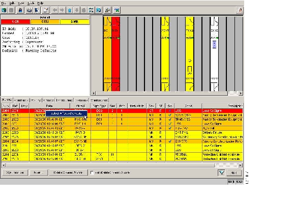
Note
The Select Affected Circuit option appears on the shortcut menu ( Figure 8-1).
Figure 8-1 Select Affected Circuits Option
Step 3
The Circuits window appears with the affected circuits highlighted.
Step 4
Stop. You have completed this procedure.
NTP-A70 View Alarm Counts on the LCD for a Node, Slot, or Port
Step 1
Step 2
Step 3
Step 4
Step 5
Step 6
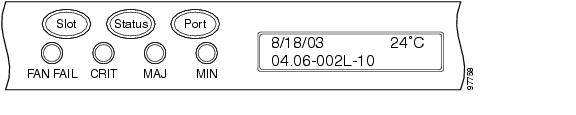
Figure 8-2 shows the shelf LCD panel.
Figure 8-2 Shelf LCD Panel
To return to the previous view from the Port screen, continue to press Port until the display cycles through all the ports on the slot. For instance, on the OC-3 card, press Port until it cycles past Slot 4 and you see "Slot."
To return to the node menu from the Slot screen, press Slot until you cycle through all the slots and see "Node."
If you do not press any buttons, the LCD will return to its default display with the node name. However, if you did not cycle through the options to return to the node status, you will see the slot or port where you last checked status.
Note
Stop. You have completed this procedure.
NTP-A71 Create, Download, and Assign Alarm Severity Profiles
Step 1
Step 2
Step 3
Note
Step 4
Step 5
Stop. You have completed this procedure.
NTP-A168 Enable, Modify, or Disable Alarm Severity Filtering
Step 1
Step 2
Step 3
Step 4
Stop. You have completed this procedure.
NTP-A72 Suppress Alarms or Discontinue Alarm Suppression
Step 1
Step 2
Note
Step 3
Stop. You have completed this procedure.
NTP-A258 Provision External Alarms and Controls on the Alarm Interface Controller-International
Note
Note
Step 1
a.
b.
Step 2
Step 3
Step 4
Step 5
Step 6
Step 7
Step 8
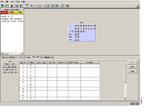
Figure 8-3 Provisioning External Alarms on The AIC-I Card
Step 9
•
•
•
The severity determines the alarm's severity in the Alarms and History tabs and determines whether the LEDs are activated. Critical (CR), Major (MJ), and Minor (MN) alarms activate the LEDs. Not Alarmed (NA) and Not Reported (NR) do not activate LEDs, but do report the information in CTC.
•
•
•
Step 10
Step 11
Step 12
•
•
•
•
Step 13
Step 14
Note
Note
Stop. You have completed this procedure.
![]()
![]()
![]()
![]()
![]()
![]()
![]()
![]()
Posted: Mon Nov 12 00:18:20 PST 2007
All contents are Copyright © 1992--2007 Cisco Systems, Inc. All rights reserved.
Important Notices and Privacy Statement.