cc/td/doc/product/ong/15400/r80docs
hometocprevnextglossaryfeedbacksearchhelp
PDF

Table Of Contents

Turn Up a Node

Before You Begin

NTP-A323 Verify Card Installation

NTP-A30 Create Users and Assign Security

NTP-A25 Set Up Name, Date, Time, and Contact Information

NTP-A261 Set Power Monitor Thresholds

NTP-A169 Set Up CTC Network Access

NTP-A358 Set Up the ONS 15454 in Secure Mode

NTP-A360 Enable EMS Secure Access

NTP-A27 Set Up the ONS 15454 for Firewall Access

NTP-A28 Set Up Timing

NTP-A324 Create Protection Groups

NTP-A256 Set Up SNMP

NTP-A318 Provision OSI


Turn Up a Node


This chapter explains how to provision a single Cisco ONS 15454 node and turn it up for service, including assigning a node name, date and time, timing references, network attributes such as IP address and default router, users and user security, and card protection groups.

Before You Begin

Complete the procedures applicable to your site plan from the following chapters:

Chapter 1, "Install the Shelf and Backplane Cable"

Chapter 2, "Install Cards and Fiber-Optic Cable"

"Connect the PC and Log into the GUI"

This section lists the chapter procedures (NTPs). Turn to a procedure for applicable tasks (DLPs).

1. A323 Verify Card Installation—Complete this procedure first.

2. A30 Create Users and Assign Security—Complete this procedure to create Cisco Transport Controller (CTC) users and assign their security levels.

3. A25 Set Up Name, Date, Time, and Contact Information—Continue with this procedure to set the node name, date, time, location, and contact information.

4. A261 Set Power Monitor Thresholds—Continue with this procedure to set the node battery power thresholds.

5. A169 Set Up CTC Network Access—Continue with this procedure to provision the IP address, default router, subnet mask, and network configuration settings.

6. A358 Set Up the ONS 15454 in Secure Mode—Continue with this procedure to connect the CTC in secure mode.

7. A360 Enable EMS Secure Access—Continue with this procedure to enable EMS secure access.

8. A27 Set Up the ONS 15454 for Firewall Access—Continue with this procedure if the ONS 15454 will be accessed behind firewalls.

9. A28 Set Up Timing—Continue with this procedure to set up the node's SONET timing references.

10. A324 Create Protection Groups—Complete this procedure, as needed, to set up 1:1, 1:N, 1+1, or Y-cable protection groups for ONS 15454 electrical and optical cards.

11. A256 Set Up SNMP—Complete this procedure if Simple Network Management Protocol (SNMP) will be used for network monitoring.

12. A318 Provision OSI—Complete this procedure if the ONS 15454 will be connected in networks with network elements (NEs) that are based on the Open System Interconnection (OSI) protocol stack. This procedure provisions the TID Address Resolution Protocol (TARP), OSI routers, manual area addresses, subnetwork points of attachment, and IP over OSI tunnels.

NTP-A323 Verify Card Installation

Purpose

This procedure verifies that an ONS 15454 node provisioned for SONET is ready for turn-up.

Tools/Equipment

An engineering work order, site plan, or other document specifying the ONS 15454 card installation.

Prerequisite Procedures

Chapter 1, "Install the Shelf and Backplane Cable"

Chapter 2, "Install Cards and Fiber-Optic Cable"

Required/As Needed

Required

Onsite/Remote

Onsite

Security Level

Retrieve or higher


Step 1 Verify that two TCC2/TCC2P cards are installed in Slots 7 and 11.

Step 2 Verify that the green ACT (active) LED is illuminated on one TCC2/TCC2P card and the amber STBY (standby) LED is illuminated on the second TCC2/TCC2P card.


Note If the TCC2/TCC2P cards are not installed, or if their LEDs are not operating as described, do not proceed. Repeat the "DLP-A36 Install the TCC2/TCC2P Cards" task on page 17-38, or refer to the Cisco ONS 15454 Troubleshooting Guide to resolve installation problems before proceeding to Step 3.


Step 3 Verify that cross-connect cards (XCVT, XC10G, or XC-VXC-10G) are installed in Slots 8 and 10. The cross-connect cards must be the same type.

Step 4 Verify that the green ACT (active) LED is illuminated on one cross-connect card and the amber STBY (standby) LED is illuminated on the second cross-connect card.


Note If the cross-connect cards are not installed, or if their LEDs are not operating as described, do not proceed. Repeat the "DLP-A37 Install the XCVT, XC10G, or XC-VXC-10G Cards" task on page 17-41, or refer to the Cisco ONS 15454 Troubleshooting Guide to resolve installation problems before proceeding to Step 5.


Step 5 If your site plan requires an AIC-I card, verify that it is installed in Slot 9 and its ACT (active) LED displays a solid green light.

Step 6 Verify that the DS-1, DS-3, EC-1, and DS3XM cards are installed in Slots 1 to 6 or 12 to 17 as designated by your installation plan.


Note The DS1/E1-56 and DS3/EC1-48 cards can only be installed in Slots 1 through 3 or 15 through 17.


Step 7 If Ethernet cards are installed, verify that the correct cross-connect cards are installed in Slots 8 and 10:

E100T-12-G and E1000-2-G cards require XC10G or XC-VXC-10G cards.

G1K-4, ML1000-2, ML100X-8, ML100T-12, and CE-1000-4 cards require XC10G or XC-VXC-10G cards if they are installed in Slots 1 to 6 or 12 to 17. If they are installed in Slots 5, 6, 11 and 12, any cross-connect card can be installed.

ML-MR-10 cards require XC10G or XC-VXC-10G cards. The ML-MR-10 card is not compatible with the XCVT or XC card.

CE-MR-10 cards can be installed in Slots 1 to 6 or 12 to 17, and can interoperate with any cross-connect card.

Step 8 If an E1000-2, E1000-2-G, G1K-4, ML100X-8, ML1000-2, CE-1000-4, CE-MR-10, or ML-MR-10 Ethernet card is installed, verify that it has a Gigabit Interface Converter (GBIC) or Small Form-Factor Pluggable (SFP) installed. If not, see the "DLP-A469 Install a GBIC or SFP/XFP Device" task on page 21-58.

Step 9 Verify that the OC-N cards (OC-3, OC-3-8, OC-12, OC-12-4, OC-48, OC-48 any slot [AS], OC-192, MRC-2.5G-4, and MRC-12) are installed in the slots designated by your site plan.

OC-3, OC-12, OC-48 AS, MRC-2.5G-4, and MRC-12 cards can be installed in Slots 1 to 6 or 12 to 17.

OC-3-8 and OC-12-4 cards can be installed in Slots 1 to 4 and 14 to 17.

OC-192 cards can be installed in Slots 5, 6, 12, or 13.

Step 10 Verify that the correct cross-connect cards are installed in Slots 8 and 10:

If an OC-192, OC-12-4, or OC-3-8 card is installed, an XC10G card must be installed.

If an OC-48 AS card is installed in Slots 1 to 4 or 14 to 17, an XC10G card must be installed. If XC or XCVT cards are installed, the OC-48 AS can be installed only in Slots 5, 6, 12, or 13.

Step 11 Verify that all installed OC-N cards display a solid amber STBY LED.

Step 12 If transponder or muxponder cards are installed (TXP_MR_10G, TXP_MR_2.5G, TXPP_MR_2.5G, MXP_MR_2.5G, MXPP_MR_2.5G, MXP_2.5G_10G, TXP_MR_10E, TXP_MR_10E_L, TXP_MR_10E_C, MXP_2.5G_10E, MXP_2.5G_10E_C, MXP_2.5G_10E_L, MXP_MR_10DME_L, MXP_MR_10DME_C, ADM-10G, GE_XP, and 10GE_XP), verify that they are installed in Slots 1 to 6 or 12 to 17 and have GBIC or SFP connectors installed. For information about installing and provisioning TXP and MXP cards, refer to the Cisco ONS 15454 DWDM Procedure Guide.

Step 13 If Fibre Channel cards (FC-MR-4) are installed, verify one of the following:

If XC10G cross-connect cards are installed, the FC-MR-4 is installed in Slots 1 to 6 or 12 to 17 and displays a solid green ACT (Active) LED.

If XCVT cross-connect cards are installed, the FC-MR-4 is installed in Slots 5 to 6 or 12 to 13 and displays a solid green ACT (Active) LED.

Step 14 Verify that fiber-optic cables (fiber) are installed and connected to the locations indicated in the site plan. If the fiber is not installed, complete the "NTP-A247 Install Fiber-Optic Cables" procedure on page 2-16.

Step 15 Verify that fiber is routed correctly in the shelf assembly and fiber boots are installed properly. If the fiber is not routed on the shelf assembly, complete the "NTP-A245 Route Fiber-Optic Cables" procedure on page 2-20. If the fiber boots are not installed, complete the "DLP-A45 Install the Fiber Boot" task on page 17-50.

Step 16 Verify that the software release shown on the LCD matches the software release indicated in your site plan. If the release does not match, perform one of the following procedures:

Perform a software upgrade using a Cisco ONS 15454 software CD. Refer to the release-specific software upgrade document for instructions.

Replace the TCC2/TCC2P cards with cards containing the correct release. Refer to the Cisco ONS 15454 Troubleshooting Guide.

Stop. You have completed this procedure.


NTP-A30 Create Users and Assign Security

Purpose

This procedure creates ONS 15454 users and assigns their security levels.

Tools/Equipment

None

Prerequisite Procedures

A323 Verify Card Installation

Required/As Needed

As needed

Onsite/Remote

Onsite or remote

Security Level

Superuser


Step 1 Complete the "DLP-A60 Log into CTC" task on page 17-62 at the node where you need to create users. If you are already logged in, continue with Step 2.


Note You must log in as a Superuser to create additional users. The CISCO15 user provided with each ONS 15454 can be used to set up other ONS 15454 users. You can add up to 500 users to one ONS 15454.


Step 2 Complete the "DLP-A74 Create a New User on a Single Node" task on page 17-78 or the "DLP-A75 Create a New User on Multiple Nodes" task on page 17-79 as needed.


Note You must add the same user name and password to each node a user will access.


Step 3 As needed, complete the "DLP-A456 Configure the Node for RADIUS Authentication" task on page 21-36. Remote Authentication Dial in User Service (RADIUS) validates remote users trying to connect to the network.

Step 4 If you want to modify the security policy settings, including password aging and idle user timeout policies, complete the "A205 Modify Users and Change Security" procedure.

Stop. You have completed this procedure.


NTP-A25 Set Up Name, Date, Time, and Contact Information

Purpose

This procedure provisions identification information for the node, including the node name, a contact name and phone number, the location of the node, and the date, time, and time zone.

Tools/Equipment

None

Prerequisite Procedures

A323 Verify Card Installation

Required/As Needed

As needed

Onsite/Remote

Onsite or remote

Security Level

Provisioning or higher


Step 1 Complete the "DLP-A60 Log into CTC" task on page 17-62 for the node you will turn up. If you are already logged in, continue with Step 2.

Step 2 Click the Provisioning > General tabs.

Step 3 Enter the following information in the fields listed:

Node Name—Type a name for the node. For Transaction Language 1 (TL1) compliance, names must begin with an alpha character and have no more than 20 alphanumeric (a-z, A-Z, 0-9) characters.

Contact—(Optional) Type the name of the node contact person and the phone number, up to 255 characters.

Latitude—Enter the node latitude: N (North) or S (South), degrees, and minutes (optional).

Longitude—Enter the node longitude: E (East) or W (West), degrees, and minutes (optional).


Tip You can drag and drop the node icon on the network view map to position nodes manually. To create the same network map visible for all ONS 15454 users, complete the "A172 Create a Logical Network Map" procedure.


CTC uses the latitude and longitude to position ONS 15454 icons on the network view map. To convert a coordinate in degrees to degrees and minutes, multiply the number after the decimal by 60. For example, the latitude 38.250739 converts to 38 degrees, 15 minutes (0.250739 x 60 = 15.0443, rounded to the nearest whole number).

Description—Type a description of the node. The description can be a maximum of 255 characters.

Use NTP/SNTP Server—When checked, CTC uses a Network Time Protocol (NTP) or Simple Network Time Protocol (SNTP) server to set the date and time of the node.

If you do not use an SNTP or NTP server, complete the Date and Time fields. The ONS 15454 will use these fields for alarm dates and times. By default, CTC displays all alarms in the CTC computer time zone for consistency. To change the display to the node time zone, complete the "DLP-A112 Display Alarms and Conditions Using Time Zone" task.


Note Using an NTP or SNTP server ensures that all ONS 15454 network nodes use the same date and time reference. The server synchronizes the node's time after power outages or software upgrades.


If you check the Use NTP/SNTP Server check box, type the IP address of one of the following:

An NTP/SNTP server connected to the ONS 15454

Another ONS 15454 with NTP/SNTP enabled that is connected to the ONS 15454

If you check gateway network element (GNE) for the ONS 15454 SOCKS proxy server (see "DLP-A249 Provision IP Settings" task on page 19-31), external ONS 15454s must reference the gateway ONS 15454 for NTP/SNTP timing. For more information about the ONS 15454 gateway settings, refer to the "Management Network Connectivity" chapter in the Cisco ONS 15454 Reference Manual.


Caution If you reference another ONS 15454 for the NTP/SNTP server, make sure the second ONS 15454 references an NTP/SNTP server and not the first ONS 15454 (that is, do not create an NTP/SNTP timing loop by having two ONS 15454 nodes reference each other).

Date—If Use NTP/SNTP Server is not checked, type the current date (mm/dd/yyyy, for example, September 24, 2002 is 09/24/2002).

Time—If Use NTP/SNTP Server is not checked, type the current time in the format hh:mm:ss, for example, 11:24:58. The ONS 15454 uses a 24-hour clock, so 10:00 PM is entered as 22:00:00.

Time Zone—Click the field and choose a city within your time zone from the drop-down list. The list displays the 80 World Time Zones from -11 through 0 (GMT) to +14. Continental United States time zones are GMT-05:00 (Eastern), GMT-06:00 (Central), GMT-07:00 (Mountain), and GMT-08:00 (Pacific).

Use Daylight Savings Time—Check this check box if the time zone that you chose uses Daylight Savings Time.

Insert AIS-V on STS-1 SD-P—Check this check box if you want Alarm Indication Signal Virtual Tributary (AIS-V) conditions inserted on VT circuits carried by STS-1s when the STS-1 crosses its Signal Degrade Path (SD-P) bit error rate (BER) threshold. On protected circuits, traffic will be switched. If the switch cannot be performed, or if circuits are not protected, traffic will be dropped when the STS-1 SD-P BER threshold is reached.

SD-P BER—If you selected Insert AIS-V, you can choose the SD-P BER level from the SD-P BER drop-down list.

Step 4 Click Apply.

Step 5 In the confirmation dialog box, click Yes.

Step 6 Review the node information. If you need to make corrections, repeat Steps 3 through 5 to enter the corrections. If the information is correct, continue with the "A261 Set Power Monitor Thresholds" procedure.

Stop. You have completed this procedure.


NTP-A261 Set Power Monitor Thresholds

Purpose

This procedure provisions extreme high, high, extreme low, and low input battery power thresholds within a -48 volts direct current (VDC) environment. When the thresholds are crossed, the TCC2/TCC2P generates warning alarms in CTC.

Tools/Equipment

None

Prerequisite Procedures

A323 Verify Card Installation

Required/As Needed

Required

Onsite/Remote

Onsite or remote

Security Level

Provisioning or higher


Step 1 Complete the "DLP-A60 Log into CTC" task on page 17-62 for the node you will set up. If you are already logged in, continue with Step 2.

Step 2 In node view, click the Provisioning > General > Power Monitor tabs.

Step 3 To change the extreme low battery voltage threshold in 0.5 VDC increments, choose a voltage from the ELWBATVG(Vdc) drop-down list.

Step 4 To change the low battery voltage threshold in 0.5 VDC increments, choose a voltage from the LWBATVG(Vdc) drop-down list.

Step 5 To change the high battery voltage threshold in 0.5 VDC increments, choose a voltage from the HIBATVG(Vdc) drop-down list.

Step 6 To change the extreme high battery voltage threshold in 0.5 VDC increments, choose a voltage from the EHIBATVG(Vdc) drop-down list.

Step 7 Click Apply.

Stop. You have completed this procedure.


NTP-A169 Set Up CTC Network Access

Purpose

This procedure provisions network access for a node, including its subnet mask, default router, Dynamic Host Configuration Protocol (DHCP) server, IIOP (Internet Inter-Orb Protocol) listener port, SOCKS proxy server settings, dual IP address setting, static routes, Open Shortest Path First (OSPF) protocol, Routing Information Protocol (RIP), and designated SOCKS servers.

Tools/Equipment

None

Prerequisite Procedures

A323 Verify Card Installation

Required/As Needed

Required

Onsite/Remote

Onsite or remote

Security Level

Superuser


Step 1 Complete the "DLP-A60 Log into CTC" task on page 17-62. If you are already logged in, continue with Step 2.

Step 2 Complete the "DLP-A249 Provision IP Settings" task on page 19-31 to provision the ONS 15454 IP address, subnet mask, default router, DHCP server, IIOP listener port, and SOCKS proxy server settings.


Tip If you cannot log into the node, you can change its IP address, default router, and network mask by using the LCD on the ONS 15454 fan-tray assembly (unless LCD provisioning is suppressed). See the "DLP-A64 Set the IP Address, Default Router, and Network Mask Using the LCD" task on page 17-66 for instructions. However, you cannot use the LCD to provision any other network settings.


Step 3 If you want to turn on the ONS 15454 secure mode, which allows two IP addresses to be provisioned for the node if TCC2P cards are installed, complete the "DLP-A433 Enable Node Secure Mode" task on page 21-10. Refer to the "Management Network Connectivity" chapter in the Cisco ONS 15454 Reference Manual for information about secure mode.


Note The node view can be accessed in secure mode. To set up the node access to CTC in secure mode, see A358 Set Up the ONS 15454 in Secure Mode.


Step 4 If static routes are needed, complete the "DLP-A65 Create a Static Route" task on page 17-68. Refer to the "Management Network Connectivity" chapter in the Cisco ONS 15454 Reference Manual for further information about static routes.

Step 5 If the ONS 15454 is connected to a LAN or WAN that uses OSPF and you want to share routing information between the LAN/WAN and the ONS network, complete the "DLP-A250 Set Up or Change Open Shortest Path First Protocol" task on page 19-35.

Step 6 If the ONS 15454 is connected to a LAN or WAN that uses RIP, complete the "DLP-A251 Set Up or Change Routing Information Protocol" task on page 19-37.

Step 7 Complete the "DLP-A558 Provision the Designated SOCKS Servers" task after the network is provisioned if SOCKS proxy is enabled and you are experiencing long login and NE discovery times. This can occur in large networks that have a high ENE-to-GNE ration and a low number of ENEs with LAN connectivity.

If these conditions do not exist, you are completed with this procedure.

Stop. You have completed this procedure.


NTP-A358 Set Up the ONS 15454 in Secure Mode

Purpose

This procedure provisions ONS 15454s and CTC computers for secure access.

Tools/Equipment

None

Prerequisite Procedures

A169 Set Up CTC Network Access

Required/As Needed

As needed

Onsite/Remote

Onsite or remote

Security Level

Superuser


Step 1 In node view, click the Provisioning > Security > Access pane.

Step 2 Under the EMS Access area, change the Access State to Secure.

Step 3 Click Apply. The CTC disconnects and reconnects through a secure socket connection.

Step 4 To create a secure connection, enter https://node-address.


Note After setting up a CTC connection in secure mode, http requests are automatically redirected to https mode.


Step 5 A first time connection is authenticated by the Website Certification is Not Known dialog box. Accept the certificate and click OK. The Security Error: Domain Name Mismatch dialog box appears. Click OK to continue.

Stop. You have completed this procedure.


NTP-A360 Enable EMS Secure Access

Purpose

This procedure enables EMS secure access.

Tools/Equipment

None

Prerequisite Procedures

A169 Set Up CTC Network Access

Required/As Needed

As needed

Onsite/Remote

Onsite or remote

Security Level

Superuser


Step 1 In shelf view, click the Provisioning > Security > Access pane.

Step 2 Under the EMS Access area, change the Access State to Secure.

Step 3 Click Apply. The CTC disconnects and reconnects through a secure socket connection.

Step 4 Set the listener port value by choosing "Other constant" radio button.

Stop. You have completed this procedure.


NTP-A27 Set Up the ONS 15454 for Firewall Access

Purpose

This procedure provisions ONS 15454s and CTC computers for access through firewalls.

Tools/Equipment

IIOP listener port number provided by your LAN or firewall administrator

Prerequisite Procedures

A323 Verify Card Installation

Required/As Needed

As needed

Onsite/Remote

Onsite or remote

Security Level

Provisioning or higher


Step 1 Log into a node that is behind the firewall. See the "DLP-A60 Log into CTC" task on page 17-62 for instructions. If you are already logged in, continue with Step 2.

Step 2 Complete the "DLP-A67 Provision the IIOP Listener Port on the ONS 15454" task on page 17-69.

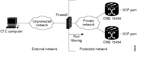
Figure 4-1 shows an ONS 15454 in a protected network and the CTC computer in an external network. For the computer to access the ONS 15454s, you must provision the IIOP listener port specified by your firewall administrator on the ONS 15454.

Figure 4-1 Nodes Behind a Firewall
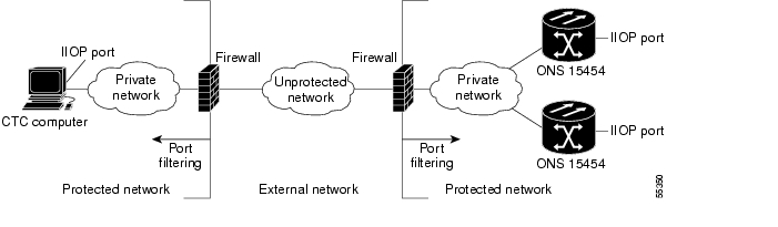
Step 3 If the CTC computer resides behind a firewall, complete the "DLP-A68 Provision the IIOP Listener Port on the CTC Computer" task on page 17-70.

Figure 4-2 shows a CTC computer and ONS 15454 behind firewalls. For the computer to access the ONS 15454, you must provision the IIOP port on the CTC computer and on the ONS 15454.

Figure 4-2 CTC Computer and ONS 15454s Residing Behind Firewalls

Stop. You have completed this procedure.


NTP-A28 Set Up Timing

Purpose

This procedure provisions the ONS 15454 timing.

Tools/Equipment

None

Prerequisite Procedures

A323 Verify Card Installation

Required/As Needed

Required

Onsite/Remote

Onsite or remote

Security Level

Provisioning or higher


Step 1 Complete the "DLP-A60 Log into CTC" task on page 17-62 at the node where you will set up timing. If you are already logged in, continue with Step 2.

Step 2 Complete the "DLP-A69 Set Up SONET External or Line Timing" task on page 17-71 if an external building integrated timing supply (BITS) source is available. This is the most common SONET timing setup procedure.

Step 3 If you cannot complete Step 2 (an external BITS source is not available), complete the "DLP-A70 Set Up Internal Timing" task on page 17-73. This task can only provide Stratum 3 timing.

Step 4 Complete the "DLP-A555 Set Up SDH External or Line Timing" task if an external BITS source providing SDH timing (64 KHz, E1, or 2 MHz) is available. Use this task for a SONET shelf running on external SDH timing.


Note For information about SONET timing, refer to the "Timing" chapter in the Cisco ONS 15454 Reference Manual or to Telcordia GR-253-CORE.


Stop. You have completed this procedure.


NTP-A324 Create Protection Groups

Purpose

This procedure creates ONS 15454 card protection groups.

Tools/Equipment

None

Prerequisite Procedures

A323 Verify Card Installation

Required/As Needed

As needed

Onsite/Remote

Onsite or remote

Security Level

Provisioning or higher


Step 1 Complete the "DLP-A60 Log into CTC" task on page 17-62 at the node where you want to create the protection group. If you are already logged in, continue with Step 2.

Table 4-1 describes the protection types available on the ONS 15454.

Table 4-1 Card Protection Types 

Type
Cards
Description and Installation Requirements

1:1

DS1-14

DS3-12

DS3-12E

DS3i-N-12

EC1-12

DS3XM-6

DS3XM-12

DS3/EC1-48

Pairs one working card with one protect card. The protect card should be installed in an odd-numbered slot and the working card in an even-numbered slot next to the protect slot towards the TCC2/TCC2P, for example: protect in Slot 1, working in Slot 2; protect in Slot 3, working in Slot 4; protect in Slot 15, working in Slot 14. 1:1 protection can be revertive or nonrevertive. For more information, refer to the "Card Protection" chapter and the card reference material specific to the card in the Cisco ONS 15454 Reference Manual.

1:N

DS1N-14

DS3N-12

DS3N-12E

DS3i-N-12

DS3XM-12

DS3/EC1-48

DS1/E1-56

Assigns one protect card for several working cards. The maximum is 1:5. These protect cards must be installed in Slot 3 or 15 and the cards they protect must be on the same side of the shelf.

Protect cards must match the cards they protect. For example, a DS1N-14 can only protect DS1-14 or DS1N-14 cards. If a failure clears, traffic reverts to the working card after the reversion time has elapsed.

For more information, refer to the "Card Protection" chapter and the card reference material specific to the card in the Cisco ONS 15454 Reference Manual.

1+1

Any OC-N

Pairs a working OC-N card/port with a protect OC-N card/port. For multiport OC-N cards, the protect port must match the working port on the working card. For example, Port 1 of an OC-3 card can only be protected by Port 1 of another OC-3 card. The ports on multiport cards must be either working or protect. You cannot mix working and protect ports on the same card. Cards do not need to be in adjoining slots. 1+1 protection can be revertive or nonrevertive, bidirectional or unidirectional.

Optimized 1+1

OC-3-4

OC-3-8

MRC-2.5G-4 (in OC-3 configurations)

Ports must be provisioned to SDH. Optimized 1+1 protection is mainly used in networks that have linear 1+1 bidirectional protection schemes. Optimized 1+1 protection is a line-level protection scheme that includes two lines, working and protect. One of the two lines assumes the role of the primary channel, from which traffic gets selected, and the other port assumes the role of the secondary channel, which protects the primary channel. Traffic switches from the primary to the secondary channel based on either an external switching command or line conditions. After the line condition or the external switching command that was responsible for a switch clears, the roles of the two sides are reversed.

Y Cable

MXP_2.5_10G

MXP_2.5_10E

MXP_2.5G_10E_C

MXP_2.5G_10E_L

MXP_MR_10DME_L

MXP_MR_10DME_C

TXP_MR_10G

TXP_MR_10E

TXP_MR_10E_L

TXP_MR_10E_C

MXP_2.5G_10E

MXP_MR_2.5G

GE_XP

10GE_XP

Pairs a working transponder or muxponder card/port with a protect transponder or muxponder card/port. The protect port must be on a different card than the working port and it must be the same card type as the working port. The working and protect port numbers must be the same, that is, Port 1 can only protect Port 1, Port 2 can only protect Port 2, etc. For more information, see the Cisco ONS 15454 DWDM Procedure Guide.

Splitter

TXPP_MR_2.5G

MXPP_MR_2.5G

Splitter protection is automatically provided with the TXPP_MR_2.5G and MXPP_MR_2.5G cards. For more information, refer to the Cisco ONS 15454 DWDM Procedure Guide.

Unprotected

Any

Unprotected cards can cause signal loss if a card fails or incurs a signal error. However, because no card slots are reserved for protection, unprotected schemes maximize the service available for use on the ONS 15454. Unprotected is the default protection type.


Step 2 Complete one or more of the following tasks depending on the protection groups you want to create:

DLP-A71 Create a 1:1 Protection Group, page 17-74

DLP-A72 Create a 1:N Protection Group, page 17-76

DLP-A73 Create a 1+1 Protection Group, page 17-77

A560 Create an Optimized 1+1 Protection Group


Note If a protect card is not installed, you can complete the "DLP-A330 Preprovision a Card Slot" task on page 20-20 and continue with the card protection provisioning.


Note A 1+1 protection group can only be provisioned between the same equipment type, using the same port number, and the same port rate. The MRC-12 cards used must be in the same slot type; either the low speed-slots or high-speed slots.


Note To create Y-cable protection groups for TXP and MXP cards, refer to the Cisco ONS 15454 DWDM Procedure Guide.


Stop. You have completed this procedure.


NTP-A256 Set Up SNMP

Purpose

This procedure provisions the SNMP parameters so that you can use SNMP management software with the ONS 15454.

Tools/Equipment

None

Prerequisite Procedures

A323 Verify Card Installation

Required/As Needed

Required if SNMP is used at your installation.

Onsite/Remote

Onsite or remote

Security Level

Provisioning or higher


Step 1 Complete the "DLP-A60 Log into CTC" task on page 17-62 at the node where you want to set up SNMP. If you are already logged in, continue with Step 2.

Step 2 In node view, click the Provisioning > SNMP tabs.

Step 3 In the Trap Destinations area, click Create.

Step 4 Complete the following in the Create SNMP Trap Destination dialog box ( Figure 4-3):

Destination IP Address—Type the IP address of your network management system. If the node you are logged into is an end network element (ENE), set the destination address to the GNE.

Community—Type the SNMP community name. For a description of SNMP community names, refer to the "SNMP" chapter in the Cisco ONS 15454 Reference Manual.


Note The community name is a form of authentication and access control. The community name assigned to the ONS 15454 is case-sensitive and must match the community name of the network management system (NMS).


UDP Port—The default User Datagram Protocol (UDP) port for SNMP is 162. (More information about provisioning the UDP port is also given in the "DLP-A449 Set Up SNMP for a GNE" task on page 21-28 and the "DLP-A450 Set Up SNMP for an ENE" task on page 21-29.)


Note If the node has the SOCKS proxy server enabled and is provisioned as an ENE, the UDP port must be set to the GNE's SNMP relay port, which is 391.


Trap Version—Choose either SNMPv1 or SNMPv2. Refer to your NMS documentation to determine whether to use SNMPv1 or SNMPv2.

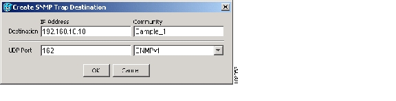
Figure 4-3 Creating an SNMP Trap

Step 5 Click OK. The node IP address of the node where you provisioned the new trap destination appears in the Trap Destinations area.

Step 6 Click the node IP address in the Trap Destinations area. Verify the SNMP information that appears in the Selected Destination list.

Step 7 If you want to set up SNMP remote monitoring (RMON) on gateway node elements (GNEs) and end node elements (ENEs), complete the following tasks as required, depending on the protection groups you want to create:

DLP-A449 Set Up SNMP for a GNE, page 21-28

DLP-A450 Set Up SNMP for an ENE, page 21-29

DLP-A451 Format and Enter NMS Community String for SNMP Command or Operation, page 21-31

Step 8 Click Apply.

Stop. You have completed this procedure.


NTP-A318 Provision OSI

Purpose

This procedure provisions the ONS 15454 so it can be networked with other vendor NEs that use the OSI protocol stack for data communications network (DCN) communications. This procedure provisions the TID TARP, OSI routers, manual area addresses, subnetwork points of attachment, and IP over OSI tunnels.

Tools/Equipment

None

Prerequisite Procedures

A323 Verify Card Installation

Required/As Needed

As needed

Onsite/Remote

Onsite or remote

Security Level

Provisioning or higher


Caution This procedure requires an understanding of OSI protocols, parameters, and functions. Before you begin, review the OSI reference sections in the "Management Network Connectivity" chapter in the Cisco ONS 15454 Reference Manual.


Caution Do not begin this procedure until you know the role of the ONS 15454 within the OSI and IP network.


Note This procedure requires provisioning of non-ONS equipment including routers and third party network elements. Do not begin until you have the capability to complete that provisioning.


Step 1 Complete the "DLP-A60 Log into CTC" task on page 17-62 at the node where you want to provision the OSI routing mode. If you are already logged in, continue with Step 2.

Step 2 As needed, complete the following tasks:

A534 Provision OSI Routing Mode—Complete this task first.

A535 Provision or Modify TARP Operating Parameters—Complete this task next.

A536 Add a Static TID to NSAP Entry to the TARP Data Cache—Complete this task as needed.

A538 Add a TARP Manual Adjacency Table Entry—Complete this task as needed.

A539 Provision OSI Routers—Complete this task as needed.

A540 Provision Additional Manual Area Addresses—Complete this task as needed.

A541 Enable the OSI Subnet on the LAN Interface—Complete this task as needed.

A542 Create an IP-Over-CLNS Tunnel—Complete this task as needed.

Stop. You have completed this procedure.


hometocprevnextglossaryfeedbacksearchhelp

Posted: Wed Nov 28 02:08:12 PST 2007
All contents are Copyright © 1992--2007 Cisco Systems, Inc. All rights reserved.
Important Notices and Privacy Statement.