cc/td/doc/product/ong/15400/r80docs
hometocprevnextglossaryfeedbacksearchhelp
PDF

Table Of Contents

Monitor Performance

Before You Begin

NTP-A253 Change the PM Display

NTP-A122 Monitor Electrical Performance

NTP-A198 Monitor Ethernet Performance

NTP-A279 Create or Delete Ethernet RMON Thresholds

NTP-A250 Monitor OC-N Performance

NTP-A347 Monitor Multirate Performance

NTP-A285 Monitor FC_MR-4 Performance

NTP-A289 Create or Delete FC_MR-4 RMON Thresholds


Monitor Performance


This chapter explains how to enable and view performance monitoring statistics for the Cisco ONS 15454. Performance monitoring (PM) parameters are used by service providers to gather, store, and set thresholds and report performance data for early detection of problems. For more PM information, details, and definition, refer to the Cisco ONS 15454 Reference Manual.

Before You Begin

Before performing any of the following procedures, investigate all alarms and clear any trouble conditions. Refer to the Cisco ONS 15454 Troubleshooting Guide as necessary.

This section lists the chapter procedures (NTPs). Turn to a procedure for applicable tasks (DLPs).

1. A253 Change the PM Display—Complete as needed to change the displayed PM counts.

2. A122 Monitor Electrical Performance—Complete as needed to monitor electrical performance.

3. A198 Monitor Ethernet Performance—Complete as needed to monitor Ethernet performance.

4. A279 Create or Delete Ethernet RMON Thresholds—Complete as needed to create or delete Ethernet remote monitoring (RMON) thresholds.

5. A250 Monitor OC-N Performance—Complete as needed to monitor optical (OC-N) performance.

6. A347 Monitor Multirate Performance—Complete as needed to monitor multirate (MRC-N) performance.

7. A285 Monitor FC_MR-4 Performance—Complete as needed to monitor FC_MR-4 performance.

8. A289 Create or Delete FC_MR-4 RMON Thresholds—Complete as needed to create or delete FC_MR-4 RMON thresholds.


Note For additional information regarding PM parameters, refer to the Digital transmission surveillance section in Telcordia's GR-1230-CORE, GR-820-CORE, GR-499-CORE, and GR-253-CORE documents, and in the ANSI document entitled Digital Hierarchy - Layer 1 In-Service Digital Transmission Performance Monitoring.


NTP-A253 Change the PM Display

Purpose

This procedure enables you to change the display of PM counts by selecting drop-down list or radio button options in the Performance window.

Tools/Equipment

None

Prerequisite Procedures

Before you monitor performance, be sure you have created the appropriate circuits and provisioned the card according to your specifications. For more information, see Chapter 6, "Create Circuits and VT Tunnels" and "Change Node Settings."

Required/As Needed

As needed

Onsite/Remote

Onsite or remote

Security Level

Retrieve or higher


Step 1 Complete the "DLP-A60 Log into CTC" task on page 17-62 at the node that you want to monitor. If you are already logged in, continue with Step 2.

Step 2 In node view, double-click the electrical, Ethernet, optical (OC-N), or multirate transport cards where you want to view PM counts. The card view appears.

Step 3 As needed, use the following tasks to change the display of PM counts:

A124 Refresh PM Counts at 15-Minute Intervals

A125 Refresh PM Counts at One-Day Intervals

DLP-A347 Refresh E-Series and G-Series Ethernet PM Counts, page 20-33

A126 View Near-End PM Counts

A127 View Far-End PM Counts

DLP-A348 Monitor PM Counts for a Selected Signal, page 20-34

A129 Reset Current PM Counts

DLP-A349 Clear Selected PM Counts, page 20-36

DLP-A458 Clear All PM Thresholds, page 21-39

DLP-A260 Set Auto-Refresh Interval for Displayed PM Counts, page 19-42

DLP-A259 Refresh Ethernet PM Counts at a Different Time Interval, page 19-41

DLP-A261 Refresh PM Counts for a Different Port, page 19-43

Stop. You have completed this procedure.


NTP-A122 Monitor Electrical Performance

Purpose

This procedure enables you to view node near-end or far-end performance during selected time intervals on an electrical card and port to detect possible performance problems.

Tools/Equipment

None

Prerequisite Procedures

Before you monitor performance, be sure you have created the appropriate circuits and provisioned the card according to your specifications. For more information, see Chapter 6, "Create Circuits and VT Tunnels" and "Change Node Settings."

Required/As Needed

As needed

Onsite/Remote

Onsite or remote

Security Level

Retrieve or higher


Step 1 Complete the "DLP-A60 Log into CTC" task on page 17-62 at the node that you want to monitor. If you are already logged in, continue with Step 3.

Step 2 Complete the following procedures depending on card type:

For DS3XM-12 cards, complete the following procedures:

DLP-A394 View DS-N/SONET PM Parameters for the DS3XM-12 Card, page 20-103

DLP-A395 View BFDL PM Parameters for the DS3XM-12 Card, page 20-105

For EC-1 cards, complete the "DLP-A122 Enable/Disable Intermediate Path Performance Monitoring" task as needed to enable or disable monitoring of synchronous transport signal (STS) traffic through intermediate nodes.

For all other electrical cards, continue with Step 3.

Step 3 In node view, double-click the electrical card where you want to view PM counts. The card view appears.

Step 4 Click the Performance tab ( Figure 9-1).

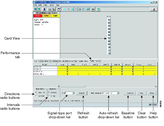
Figure 9-1 Viewing Electrical Card Performance Monitoring Information

Step 5 In the signal-type drop-down lists, choose the applicable port on the card you selected.

Step 6 Click Refresh.

Step 7 View the PM parameter names that appear in the Param column. The PM parameter values appear in the Curr (current) and Prev-n (previous) columns. For PM parameter definitions, refer to the "Performance Monitoring" chapter in the Cisco ONS 15454 Reference Manual.

To refresh, reset, or clear PM counts, see the "A253 Change the PM Display" procedure.

Stop. You have completed this procedure.


NTP-A198 Monitor Ethernet Performance

Purpose

This procedure enables you to view node transmit and receive performance during selected time intervals on an Ethernet card and port to detect possible performance problems.

Tools/Equipment

None

Prerequisite Procedures

Before you monitor performance, be sure you have created the appropriate circuits and provisioned the card according to your specifications. For more information, see Chapter 6, "Create Circuits and VT Tunnels" and "Change Node Settings."

Required/As Needed

As needed

Onsite/Remote

Onsite

Security Level

Retrieve or higher


Step 1 Complete the "DLP-A60 Log into CTC" task on page 17-62 at the node that you want to monitor. If you are already logged in, continue with Step 2.

Step 2 Complete the "DLP-A256 View Ethernet Statistics PM Parameters" task on page 19-39.

Step 3 Complete the "DLP-A257 View Ethernet Utilization PM Parameters" task on page 19-40.

Step 4 Complete the "DLP-A258 View Ethernet History PM Parameters" task on page 19-41.

Step 5 Complete the "DLP-A320 View ML-Series Ether Ports PM Parameters" task on page 20-10.

Step 6 Complete the "DLP-A321 View ML-Series POS Ports PM Parameters" task on page 20-12.

Step 7 Complete the "DLP-A562 View ML-Series RPR Span PM Parameters" task.

Step 8 Complete the "DLP-A391 View CE-Series Ether Ports and POS Ports Statistics PM Parameters" task on page 20-99.

Step 9 Complete the "DLP-A392 View CE-Series Ether Ports and POS Ports Utilization PM Parameters" task on page 20-100.

Step 10 Complete the "DLP-A393 View CE-Series Ether Ports and POS Ports History PM Parameters" task on page 20-102.

Stop. You have completed this procedure.


NTP-A279 Create or Delete Ethernet RMON Thresholds

Purpose

This procedure creates or deletes Ethernet RMON thresholds for the ONS 15454.

Tools/Equipment

None

Prerequisite Procedures

None

Required/As Needed

As needed

Onsite/Remote

Onsite or remote

Security Level

Provisioning or higher


Step 1 Complete the "DLP-A60 Log into CTC" task on page 17-62. If you are already logged in, continue with Step 2.

Step 2 Perform any of the following tasks as needed:

A533 Create Ethernet RMON Alarm Thresholds

A529 Delete Ethernet RMON Alarm Thresholds

Stop. You have completed this procedure.


NTP-A250 Monitor OC-N Performance

Purpose

This procedure enables you to view node near-end or far-end performance during selected time intervals on an OC-N card and port to detect possible performance problems.

Tools/Equipment

None

Prerequisite Procedures

Before you monitor performance, be sure you have created the appropriate circuits and provisioned the card according to your specifications. For more information, see Chapter 6, "Create Circuits and VT Tunnels" and "Change Node Settings."

Required/As Needed

As needed

Onsite/Remote

Onsite or remote

Security Level

Retrieve or higher


Step 1 Complete the "DLP-A60 Log into CTC" task on page 17-62 at the node that you want to monitor. If you are already logged in, continue with Step 2.

Step 2 Complete the "DLP-A121 Enable/Disable Pointer Justification Count Performance Monitoring" task as needed to enable or disable clock synchronization monitoring.

Step 3 Complete the "DLP-A122 Enable/Disable Intermediate Path Performance Monitoring" task as needed to enable or disable monitoring of STS traffic through intermediate nodes.

Step 4 Complete the "DLP-A507 View OC-N PM Parameters" task.

To refresh, reset, or clear PM counts, see the "A253 Change the PM Display" procedure.

Stop. You have completed this procedure.


NTP-A347 Monitor Multirate Performance

Purpose

This procedure enables you to view node near-end or far-end performance during selected time intervals on an MRC-N card and port to detect possible performance problems.

Tools/Equipment

None

Prerequisite Procedures

Before you monitor performance, be sure you have created the appropriate circuits and provisioned the card according to your specifications. For more information, see Chapter 6, "Create Circuits and VT Tunnels" and "Change Node Settings."

Required/As Needed

As needed

Onsite/Remote

Onsite or remote

Security Level

Retrieve or higher


Step 1 Complete the "DLP-A60 Log into CTC" task on page 17-62 at the node that you want to monitor. If you are already logged in, continue with Step 2.

Step 2 Complete the "DLP-A121 Enable/Disable Pointer Justification Count Performance Monitoring" task as needed to enable or disable clock synchronization monitoring.

Step 3 Complete the "DLP-A122 Enable/Disable Intermediate Path Performance Monitoring" task as needed to enable or disable monitoring of STS traffic through intermediate nodes.

Step 4 Complete the "DLP-A557 View Multirate PM Parameters" task.

To refresh, reset, or clear PM counts, see the "A253 Change the PM Display" procedure.

Stop. You have completed this procedure.


NTP-A285 Monitor FC_MR-4 Performance

Purpose

This procedure enables you to view node transmit and receive performance during selected time intervals on an FC_MR-4 card and port to detect possible performance problems.

Tools/Equipment

None

Prerequisite Procedures

Before you monitor performance, be sure you have created the appropriate circuits and provisioned the card according to your specifications. For more information, see Chapter 6, "Create Circuits and VT Tunnels" and "Change Node Settings."

Required/As Needed

As needed

Onsite/Remote

Onsite

Security Level

Retrieve or higher


Step 1 Complete the "DLP-A60 Log into CTC" task on page 17-62 at the node that you want to monitor. If you are already logged in, continue with Step 2.

Step 2 Complete the "DLP-A350 View FC_MR-4 Statistics PM Parameters" task on page 20-37.

Step 3 Complete the "DLP-A351 View FC_MR-4 Utilization PM Parameters" task on page 20-38.

Step 4 Complete the "DLP-A352 View FC_MR-4 History PM Parameters" task on page 20-39.

Stop. You have completed this procedure.


NTP-A289 Create or Delete FC_MR-4 RMON Thresholds

Purpose

Use this procedure to create or delete FC_MR-4 RMON thresholds for the ONS 15454.

Tools/Equipment

None

Prerequisite Procedures

None

Required/As Needed

As needed

Onsite/Remote

Onsite or remote

Security Level

Provisioning or higher


Step 1 Complete the "DLP-A60 Log into CTC" task on page 17-62. If you are already logged in, continue with Step 2.

Step 2 Perform any of the following tasks as needed:

DLP-A357 Create FC_MR-4 RMON Alarm Thresholds, page 20-41

DLP-A358 Delete FC_MR-4 RMON Alarm Thresholds, page 20-45

Stop. You have completed this procedure.


hometocprevnextglossaryfeedbacksearchhelp

Posted: Mon Nov 12 00:20:38 PST 2007
All contents are Copyright © 1992--2007 Cisco Systems, Inc. All rights reserved.
Important Notices and Privacy Statement.