cc/td/doc/product/ong/15400/r80docs
hometocprevnextglossaryfeedbacksearchhelp
PDF

Table Of Contents

Convert Network Configurations

Before You Begin

NTP-A335 Convert a 1+1 Point-to-Point to a Linear ADM Automatically

NTP-A154 Convert a 1+1 Point-to-Point to a Linear ADM Manually

NTP-A303 Convert an Unprotected Point-to-Point or 1+1 Linear ADM to a Two-Fiber BLSR Automatically

NTP-A155 Convert a 1+1 Point-to-Point or a Linear ADM to a Two-Fiber BLSR Manually

NTP-A342 Convert a Point-to-Point or Linear ADM to a Path Protection Automatically

NTP-A156 Convert a Point-to-Point or Linear ADM to a Path Protection Manually

NTP-A267 Convert a Path Protection to a Two-Fiber BLSR Automatically

NTP-A210 Convert a Path Protection to a Two-Fiber BLSR Manually

NTP-A211 Convert a Two-Fiber BLSR to a Four-Fiber BLSR Automatically

NTP-A159 Modify a BLSR


Convert Network Configurations


This chapter explains how to convert from one SONET topology to another in a Cisco ONS 15454 network. For initial network turn up, see "Turn Up a Network."

Before You Begin

This section lists the chapter procedures (NTPs). Turn to a procedure for applicable tasks (DLPs).

1. A335 Convert a 1+1 Point-to-Point to a Linear ADM Automatically—Complete as needed.

2. A154 Convert a 1+1 Point-to-Point to a Linear ADM Manually—Complete as needed if the in-service topology upgrade wizard is not available or you need to back out of the wizard.

3. A303 Convert an Unprotected Point-to-Point or 1+1 Linear ADM to a Two-Fiber BLSR Automatically—Complete as needed.

4. A155 Convert a 1+1 Point-to-Point or a Linear ADM to a Two-Fiber BLSR Manually—Complete as needed if the in-service topology upgrade wizard is not available or you need to back out of the wizard.

5. A342 Convert a Point-to-Point or Linear ADM to a Path Protection Automatically—Complete as needed.

6. A156 Convert a Point-to-Point or Linear ADM to a Path Protection Manually—Complete as needed if the in-service topology upgrade wizard is not available or you need to back out of the wizard.

7. A267 Convert a Path Protection to a Two-Fiber BLSR Automatically—Complete as needed.

8. A210 Convert a Path Protection to a Two-Fiber BLSR Manually—Complete as needed if the in-service topology upgrade wizard is not available or you need to back out of the wizard.

9. A211 Convert a Two-Fiber BLSR to a Four-Fiber BLSR Automatically—Complete as needed.

10. A159 Modify a BLSR—Complete as needed to change the BLSR ring name, ring or span reversion times, or node ID.

NTP-A335 Convert a 1+1 Point-to-Point to a Linear ADM Automatically

Purpose

This procedure converts a 1+1 point-to-point (terminal) configuration (two nodes) to a 1+1 linear add-drop multiplexer (ADM) (3 nodes) without losing traffic.

Tools/Equipment

Compatible hardware

Attenuators might be needed for some applications.

Prerequisite Procedures

This procedure requires that the node to be added is reachable (has IP connectivity with CTC). Two technicians who can communicate with each other during the upgrade might be needed if the PC running CTC and the ONS 15454 nodes are not at the same location.

Required/As Needed

As needed

Onsite/Remote

Onsite

Security Level

Provisioning or higher


Note OC-N transmit and receive levels should be in their acceptable range as shown in the specifications for each card in the Table 2-5 on page 2-18.


Note If overhead circuits exist on the network, this procedure is service affecting. The overhead circuits will drop traffic and have a status of PARTIAL after the upgrade is complete.


Step 1 Complete the "DLP-A60 Log into CTC" task on page 17-62 at one of the two point-to-point nodes. If you are already logged in, continue with Step 2.

Step 2 In network view, right-click the span between the two nodes where you want to add the new node. A dialog box appears.

Step 3 Select Upgrade Protection. A drop-down list appears.

Step 4 Select Terminal to Linear and the first page of the Upgrade Protection: Terminal to Linear wizard appears.

Step 5 The first page of the wizard lists the following conditions for adding a new node:

The terminal network has no critical or major alarms.

The node that you will add has no critical or major alarms.

The node has compatible software version with that of the terminal nodes.

The node has four unused optical ports matching the speed of the 1+1 protection and no communication channel has been provisioned on these four ports.

Fiber is available to connect the added node to the terminal nodes.

If all of these conditions are met and you wish to continue with the procedure, click Next.


Note If you are attempting to add an unreachable node, you must first log in to the unreachable node using a separate CTC session and configure that node. Delete any existing protection groups as described in the "DLP-A155 Delete a Protection Group" task. Delete any existing DCC terminations as described in the "DLP-A156 Delete a Section DCC Termination" task and the "DLP-A359 Delete a Line DCC Termination" task on page 20-46.


Step 6 Enter the node host name or IP address or choose the name of the new node from the drop-down list. If you type in the name, make sure it is identical to the actual node name. The node name is case sensitive.

Step 7 Click Next. The Select Protection Group Ports page ( Figure 13-1) appears.

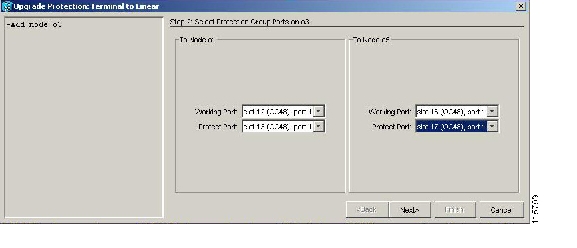
Figure 13-1 Selecting Protection Group Ports

Step 8 Select the working and protect ports on the new node in the drop-down lists that you want to connect to each terminal node.

Step 9 Click Next. The Re-fiber the Protected Path dialog box appears ( Figure 13-2).

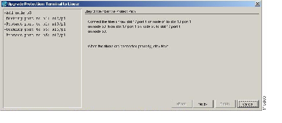
Figure 13-2 Refibering the Protect Path

Step 10 Follow the instructions in the Re-fiber the Protected Path dialog box for connecting the fibers between the nodes.

Step 11 When the fibers are connected properly, click Next. The Update Circuit(s) on Node-Name dialog box appears.


Note The Back button is not enabled in the wizard. You can click the Cancel button at this point and choose the Yes button if you want to cancel the Upgrade Protection procedure. If the procedure fails after you have physically moved the fiber-optic cables, you must restore the fiber-optic cables to the original positions and verify (through CTC) that traffic is on the working path of the nodes before restarting the process. To check traffic status, go to node view, click the Maintenance > Protection tabs. In the Protection Groups area, click the 1+1 protection group. You can see the status of the traffic in the Selected Group area.


Step 12 Click Next on the Update Circuit(s) on Node-Name page to continue with the procedure.

Step 13 The Force Traffic to Protect Path page states that it is about to force the traffic from the working to protect path for the terminal nodes. When you are ready to proceed, click Next.

Step 14 Follow each step as instructed by the wizard as it guides you through the process of refibering the working path between nodes and forcing the traffic back to the working path.

Step 15 The Force Traffic to Working Path page states that it is about to force the traffic from the protect to working path for the terminal nodes. When you are ready to proceed, click Next.

Step 16 The Completed page appears. This page is the final one in the process. Click Finish.

Stop. You have completed this procedure.


NTP-A154 Convert a 1+1 Point-to-Point to a Linear ADM Manually

Purpose

This procedure upgrades a 1+1 point-to-point configuration (two nodes) to a linear ADM configuration (three or more nodes) manually, that is, without using the in-service topology upgrade wizard. Use this procedure if the wizard is unavailable or if you need to back out of the wizard.

Tools/Equipment

None

Prerequisite Procedures

A124 Provision a Point-to-Point Network

Required/As Needed

As needed

Onsite/Remote

Onsite

Security Level

Provisioning or higher


Caution This procedure is service-affecting.


Note Optical transmit and receive levels should be in their acceptable range as shown in the specifications section for each card in Table 2-5 on page 2-18.


Note In a point-to-point configuration, two OC-N cards are connected to two OC-N cards on a second node. The working OC-N ports have data communications channel (DCC) terminations, and the OC-N cards are in a 1+1 protection group.


Step 1 Complete the "DLP-A60 Log into CTC" task on page 17-62 at one of the two point-to-point nodes. If you are already logged in, continue with Step 2.

Step 2 Complete the "DLP-A298 Check the Network for Alarms and Conditions" task on page 19-63.

Step 3 Log into the node that will be added to the point-to-point configuration (the new node).


Note If you are attempting to add an unreachable node you must first log in to the unreachable node using a separate CTC session and configure that node. Delete any existing protection groups as described in the "DLP-A155 Delete a Protection Group" task. Delete any existing DCC terminations as described in the "DLP-A156 Delete a Section DCC Termination" task or the "DLP-A359 Delete a Line DCC Termination" task on page 20-46.


Step 4 Complete the "A323 Verify Card Installation" procedure to ensure that the new node has two OC-N cards with the same rate as the point-to-point nodes.

Step 5 Complete the "A35 Verify Node Turn-Up" procedure for the new node.

Step 6 Physically connect the fibers between the point-to-point node and the new node. The fiber connections should be connected from working card to working card and protect card to protect card.

Step 7 On the new node, create a 1+1 protection group for the OC-N cards in the point-to-point node that will connect to the point-to-point node. See the "DLP-A73 Create a 1+1 Protection Group" task on page 17-77.

Step 8 Complete the "DLP-A377 Provision Section DCC Terminations" task on page 20-69 for the working OC-N cards in the new node that will connect to the linear ADM network. Alternatively, if additional bandwidth is needed for CTC management, complete the "DLP-A378 Provision Line DCC Terminations" task on page 20-71.


Note DCC failure alarms appear until you create DCC terminations in the point-to-point node during Step 9.


Step 9 In node view, display the point-to-point node that will connect to the new node.

Step 10 Complete the "A323 Verify Card Installation" procedure to ensure that the point-to-point node has OC-N cards installed that can connect to the new node.

Step 11 Create a 1+1 protection group for the OC-N cards that will connect to the new node. See the "DLP-A73 Create a 1+1 Protection Group" task on page 17-77 for instructions.

Step 12 Create DCC terminations on the working OC-N card that will connect to the new node. See the "DLP-A377 Provision Section DCC Terminations" task on page 20-69.

Step 13 From the View menu, choose Go to Node View to open the new node in node view.

Step 14 Complete the "A28 Set Up Timing" procedure for the new node. If the new node is using line timing, make the working OC-N card the timing source.

Step 15 From the View menu, choose Go to Network View. Verify that the newly created linear ADM configuration is correct. One green span line should appear between each linear node.

Step 16 Click the Alarms tab.

a. Verify that the alarm filter is not on. See the "DLP-A227 Disable Alarm Filtering" task on page 19-18 as necessary.

b. Verify that no unexplained alarms appear on the network. If alarms appear, investigate and resolve them before continuing. Refer to the Cisco ONS 15454 Troubleshooting Guide for procedures.

Step 17 Repeat the procedure to add an additional node to the linear ADM.

Stop. You have completed this procedure.


NTP-A303 Convert an Unprotected Point-to-Point or 1+1 Linear ADM to a Two-Fiber BLSR Automatically

Purpose

This procedure converts an unprotected point-to-point (two nodes) or linear ADM (three or more nodes) to a two-fiber bidirectional line switched ring (BLSR) without disrupting traffic.

Tools/Equipment

None

Prerequisite Procedures

A44 Provision Path Protection Nodes

Required/As Needed

As needed

Onsite/Remote

Onsite or remote

Security Level

Provisioning or higher


Note Before beginning this procedure, you should have a unique ring name to identify the new BLSR and a unique node ID number for each node in the ring.


Note Before beginning this procedure, optical transmit and receive levels should be in their acceptable range as shown in Table 2-5 on page 2-18.


Note If overhead circuits exist on the network, this procedure is service affecting. The overhead circuits will drop traffic and have a status of PARTIAL after the upgrade is complete.


Step 1 Complete the "DLP-A60 Log into CTC" task on page 17-62 at a node on the point-to-point or linear ADM. If you are already logged in, continue with Step 2.

Step 2 Complete the "DLP-A298 Check the Network for Alarms and Conditions" task on page 19-63.

Step 3 Complete the "DLP-A155 Delete a Protection Group" task at the nodes that support the point-to-point or linear ADM span to remove any protection groups that may exist.

Step 4 Complete the "DLP-A377 Provision Section DCC Terminations" task on page 20-69 at the nodes that support the point-to-point or linear ADM span. Provision the slot in each node that is not already in the SDCC Terminations list.

Step 5 From the Tools menu, choose Topology Upgrade > Convert Path Protection to BLSR. In the Topology Conversion dialog box, set the BLSR properties:

Ring Type—(Display only.) The default is two-fiber.

Speed—Choose the BLSR ring speed: OC-12, OC-48, or OC-192. The speed must match the OC-N speed of the BLSR trunk (span) cards.


Note If you are creating an OC-12 BLSR and will eventually upgrade it to OC-48 or OC-192, use the single-port OC-12 cards (OC12 IR/STM4 SH 1310, OC12 LR/STM4 SH 1310, or OC12 LR/STM4 LH 1550).


Ring Name—Assign a ring name. The name can be from 1 to 6 characters in length. Any alphanumeric string is permissible, and upper and lower case letters can be combined. Do not use the character string "All" in either upper or lower case letters. This is a TL1 keyword and will be rejected. Do not choose a name that is already assigned to another BLSR.

Reversion time—Set the amount of time that will pass before the traffic reverts to the original working path following a ring switch. The default is 5 minutes. Ring reversions can be set to Never.

Step 6 Click Next. If the network graphic appears, go to Step 7.

If CTC determines that a BLSR cannot be created, for example, not enough optical cards are installed or it finds circuits with path protection selectors, a "Cannot Create BLSR" message appears. If this occurs, complete the following steps:

a. Click OK.

b. In the Create BLSR window, click Excluded Nodes. Review the information explaining why the BLSR could not be created, then click OK.

c. Depending on the problem, click Back to start over or click Cancel to cancel the operation.

d. Complete the "A40 Provision BLSR Nodes" procedure, making sure all steps are completed accurately, then start this procedure again.

Step 7 In the network graphic, double-click a BLSR span line. If the span line is DCC connected to other BLSR cards that constitute a complete ring, the lines turn blue. If the lines do not form a complete ring, double-click span lines until a complete ring is formed. Click Next.

Step 8 The path protection to BLSR Topology Conversion dialog box appears. The dialog box states that the system is about to force traffic to the shortest path protection paths. Click Next.

Step 9 Another dialog box appears, stating that the force has been applied to the shortest path protection path. Click Finish.

If the BLSR window appears with the BLSR you created, go to the next step. If a "Cannot Create BLSR" or "Error While Creating BLSR" message appears:

a. Click OK.

b. In the Create BLSR window, click Excluded Nodes. Review the information explaining why the BLSR could not be created, then click OK.

c. Depending on the problem, click Back to start over or click Cancel to cancel the operation.

d. Complete the "A40 Provision BLSR Nodes" procedure, making sure all steps are completed accurately, then start this procedure again.


Note Some or all of the following alarms might briefly appear during BLSR setup: E-W MISMATCH, RING MISMATCH, APSCIMP, APSDFLTK, and BLSROSYNC.


Step 10 Verify the following:

On the network view graphic, a green span line appears between all BLSR nodes.

All E-W MISMATCH, RING MISMATCH, APSCIMP, DFLTK, and BLSROSYNC alarms are cleared. See the Cisco ONS 15454 Troubleshooting Guide for alarm troubleshooting.


Note The numbers in parentheses after the node name are the BLSR node IDs assigned by CTC. Every ONS 15454 in a BLSR is given a unique node ID, 0 through 31. To change it, complete the "DLP-A326 Change a BLSR Node ID" task on page 20-16.


Stop. You have completed this procedure.


NTP-A155 Convert a 1+1 Point-to-Point or a Linear ADM to a Two-Fiber BLSR Manually

Purpose

This procedure upgrades a 1+1 point-to-point configuration (two nodes) or a linear ADM configuration (three or more nodes) to a two-fiber BLSR manually, that is, without using the in-service topology upgrade wizard. Use this procedure if the wizard is unavailable or if you need to back out of the wizard.

Tools/Equipment

None

Prerequisite Procedures

A124 Provision a Point-to-Point Network or

A38 Provision a Linear ADM Network

Required/As Needed

As needed

Onsite/Remote

Onsite

Security Level

Provisioning or higher


Note Optical transmit and receive levels should be in their acceptable range as shown in Table 2-5 on page 2-18.


Caution Traffic is not protected during this procedure.


Step 1 Complete the "DLP-A60 Log into CTC" task on page 17-62 at one of the nodes that you want to convert from a point-to-point or ADM to a BLSR. If you are already logged in, continue with Step 2.

Step 2 According to local site practice, complete the "NTP-A108 Back Up the Database" procedure on page 15-5 for each node in the configuration.

Step 3 Complete the "DLP-A298 Check the Network for Alarms and Conditions" task on page 19-63.

Step 4 On the network map, right-click a span adjacent to the node you are logged into. A shortcut menu appears.

Step 5 From the shortcut menu, click Circuits. The Circuits on Span window appears.

Step 6 Verify that the total number of active STS circuits does not exceed 50 percent of the span bandwidth. In the Circuits column there is a block titled "Unused." This number should exceed 50 percent of the span bandwidth.

If the span is an OC-48, no more than 24 STSs can be provisioned on the span. If the span is an OC-192, no more than 96 STSs can be provisioned on the span. If the span is an OC-12, no more than 6 STSs can be provisioned on the span.


Caution If the upper STSs are in use, this procedure cannot be completed. Bandwidth must be 50 percent unassigned to convert to a BLSR. Refer to local procedures for relocating circuits if these requirements are not met.

Step 7 Repeat Steps 4 through 6 for each node in the point-to-point or linear ADM that you will convert to a BLSR. When all nodes comply with Step 6, proceed to the next step.

Step 8 For every node in the point-to-point or linear ADM network that you want to convert to a BLSR, complete the following tasks:

a. Complete the "DLP-A189 Verify that a 1+1 Working Slot is Active" task for every 1+1 protection group that supports a span in the point-to-point or linear ADM network.

b. Complete the "DLP-A155 Delete a Protection Group" task at each port that supports the point-to-point or linear ADM span.

c. Complete the "DLP-A214 Change the Service State for a Port" task on page 19-9 to put the protect ports out of service at each node that supports the point-to-point or linear ADM span.

Step 9 (Linear ADM only.) Physically remove the protect fibers from all nodes in the linear ADM; for example, the fiber running from Node 2/Slot 13 to Node 3/Slot 13 (as shown in Figure 13-3) can be removed.

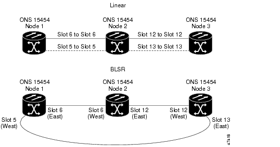
Figure 13-3 Linear ADM to BLSR Conversion

Step 10 Create the ring by connecting the protect fiber from one end node to the protect port on the other end node. For example, the fiber between Node 1/Slot 5 and Node 2/Slot 5 (as shown in Figure 13-3) can be rerouted to connect Node 1/Slot 5 to Node 3/Slot 13.


Note If you need to remove any OC-N cards from the shelf, do so now. In this example, cards in Node 2/Slots 5 and 13 can be removed. See the "NTP-A116 Remove and Replace a Card" procedure on page 2-20.


Step 11 From the network view, click the Circuits tab and complete the "DLP-A532 Export CTC Data" task to save the circuit data to a file on your hard drive.

Step 12 Complete the "DLP-A377 Provision Section DCC Terminations" task on page 20-69 at the end nodes. Provision the slot in each node that is not already in the SDCC Terminations list (in the Figure 13-3 example, Port 1 of Node 1/Slot 5 and Port 1 of Node 3/Slot 13).

Step 13 For circuits provisioned on an STS that is now part of the protection bandwidth (STSs 7 to 12 for an OC-12 BLSR, STSs 25 to 48 for an OC-48 BLSR, and STSs 97 to 192 for an OC-192 BLSR), delete and recreate each circuit:

a. Complete the "DLP-A333 Delete Circuits" task on page 20-21 for one circuit.

b. Create the circuit on STSs 1 to 6 for an OC-12 BLSR, STSs 1 to 24 for an OC-48 BLSR, or STSs 1 to  96 for an OC-192 BLSR on the fiber that served as the protect fiber in the linear ADM. See the "NTP-A344 Create a Manually Routed Optical Circuit" procedure on page 6-45 for instructions.

c. Repeat Steps a and b for each circuit residing on a BLSR protect STS.

Step 14 Complete the "A126 Create a BLSR" procedure to put the nodes into a BLSR.

Stop. You have completed this procedure.


NTP-A342 Convert a Point-to-Point or Linear ADM to a Path Protection Automatically

Purpose

This procedure upgrades a point-to-point or linear ADM to a path protection without disrupting traffic. You can upgrade STS, VT, and VT tunnel circuits to path protection. This option is a single circuit operation.

Tools/Equipment

None

Prerequisite Procedures

A124 Provision a Point-to-Point Network

Required/As Needed

As needed

Onsite/Remote

Onsite or remote

Security Level

Provisioning or higher


Note When upgrading VT tunnels, CTC does not convert the VT tunnel to path protection, but instead creates a secondary tunnel for the alternate path. The result is two unprotected VT tunnels using alternate paths.


Note If overhead circuits exist on the network, this procedure is service affecting. The overhead circuits will drop traffic and have a status of PARTIAL after the upgrade is complete.


Step 1 Complete the "DLP-A60 Log into CTC" task on page 17-62 at a node on the point-to-point or linear ADM. If you are already logged in, continue with Step 2.

Step 2 If the point-to-point or linear ADM is 1+1 protected, complete the "DLP-A155 Delete a Protection Group" task. If the point-to-point or linear ADM is unprotected, continue with Step 4.

Step 3 Complete the "DLP-A377 Provision Section DCC Terminations" task on page 20-69 at the protect cards in all nodes that will be part of the path protection. Alternatively, if additional bandwidth is needed for CTC management, complete the "DLP-A378 Provision Line DCC Terminations" task on page 20-71.

Step 4 From either network or node view, click the Circuits tab. Click the circuit you want to upgrade to select it.

Step 5 From the Tools menu, choose Topology Upgrade > Convert Unprotected to Path Protection.

Step 6 To set the path protection parameters, complete the "DLP-A218 Provision Path Protection Selectors" task on page 19-12.


Note When upgrading point-to-point or linear ADM circuits to a path protection topology, a traffic hit of greater than 300ms occurs if the "Provision working go & return on primary path" routing option is not checked in the Circuit Attributes pane.


Step 7 Click Next.

Step 8 Complete one of the following tasks:

a. To route the new path protection circuit manually, complete "DLP-A397 Manually Route a Path Protection Circuit for a Topology Upgrade" task on page 20-106.

b. To route the new path protection circuit automatically, complete "DLP-A398 Automatically Route a Path Protection Circuit for a Topology Upgrade" task on page 20-107.

Stop. You have completed this procedure.


NTP-A156 Convert a Point-to-Point or Linear ADM to a Path Protection Manually

Purpose

This procedure upgrades a point-to-point system to a path protection manually, that is, without using the in-service topology upgrade wizard. Use this procedure if the wizard is unavailable or if you need to back out of the wizard.

Tools/Equipment

None

Prerequisite Procedures

A124 Provision a Point-to-Point Network or

A38 Provision a Linear ADM Network

Required/As Needed

As needed

Onsite/Remote

Onsite or remote

Security Level

Provisioning or higher


Caution This procedure is service affecting. All circuits are deleted and reprovisioned.


Step 1 Complete the "DLP-A60 Log into CTC" task on page 17-62 at a node on the point-to-point or linear ADM. If you are already logged in, continue with Step 2.

Step 2 Complete the "DLP-A298 Check the Network for Alarms and Conditions" task on page 19-63.

Step 3 Complete the "DLP-A189 Verify that a 1+1 Working Slot is Active" task for each node.

Step 4 Complete the "DLP-A155 Delete a Protection Group" task for each 1+1 protection group that supports the point-to-point or linear ADM span.

Step 5 Complete the "DLP-A377 Provision Section DCC Terminations" task on page 20-69 at the protect cards in all nodes that will be part of the path protection. Alternatively, if additional bandwidth is needed for CTC management, complete the "DLP-A378 Provision Line DCC Terminations" task on page 20-71.

Step 6 Complete the "DLP-A333 Delete Circuits" task on page 20-21 and the "NTP-A343 Create an Automatically Routed Optical Circuit" procedure on page 6-40 to delete and recreate the circuits one at a time.


Note A path protection is the default configuration if the cards installed are installed and the DCCs are configured.


Stop. You have completed this procedure.


NTP-A267 Convert a Path Protection to a Two-Fiber BLSR Automatically

Purpose

This procedure converts a path protection to a two-fiber BLSR without disrupting traffic.

Tools/Equipment

None

Prerequisite Procedures

A44 Provision Path Protection Nodes

Required/As Needed

As needed

Onsite/Remote

Onsite or remote

Security Level

Provisioning or higher


Note Open-ended path protection and path protection dual-ring interconnect (DRI) configurations do not support in-service topology upgrades.


Note Before beginning this procedure, you should have a unique ring name to identify the new BLSR and a unique node ID number for each node on the ring.


Note Before beginning this procedure, optical transmit and receive levels should be in their acceptable range as shown in Table 2-5 on page 2-18.


Note If overhead circuits exist on the network, this procedure is service affecting. The overhead circuits will drop traffic and have a status of PARTIAL after the upgrade is complete.


Step 1 Complete the "DLP-A60 Log into CTC" task on page 17-62 at a node on the path protection. If you are already logged in, continue with Step 2.

Step 2 Complete the "DLP-A298 Check the Network for Alarms and Conditions" task on page 19-63.

Step 3 In the path protection to BLSR Topology Conversion dialog box, set the BLSR properties:

Ring Type—(Display only.) The default is two-fiber.

Speed—Choose the BLSR ring speed: OC-12, OC-48, or OC-192. The speed must match the OC-N speed of the BLSR trunk (span) cards.


Note If you are creating an OC-12 BLSR and will eventually upgrade it to OC-48 or OC-192, use the single-port OC-12 cards (OC12 IR/STM4 SH 1310, OC12 LR/STM4 SH 1310, or OC12 LR/STM4 LH 1550).


Ring Name—Assign a ring name. The name can be from 1 to 6 characters in length. Any alphanumeric string is permissible, and upper and lower case letters can be combined. Do not use the character string "All" in either upper or lower case letters. This is a TL1 keyword and will be rejected. Do not choose a name that is already assigned to another BLSR.

Reversion time—Set the amount of time that will pass before the traffic reverts to the original working path following a ring switch. The default is 5 minutes. Ring reversions can be set to Never.

Step 4 Click Next. If the network graphic appears, go to Step 5.

If CTC determines that a BLSR cannot be created, for example, if not enough optical cards are installed or if it finds circuits with path protection selectors, a "Cannot Create BLSR" message appears. If this occurs, complete the following steps:

a. Click OK.

b. In the Create BLSR window, click Excluded Nodes. Review the information explaining why the BLSR could not be created, then click OK.

c. Depending on the problem, click Back to start over or click Cancel to cancel the operation.

d. Complete the "A40 Provision BLSR Nodes" procedure, making sure all steps are completed accurately, then start this procedure again.

Step 5 In the network graphic, double-click a BLSR span line. If the span line is DCC connected to other BLSR cards that constitute a complete ring, the lines turn blue. If the lines do not form a complete ring, double-click span lines until a complete ring is formed. Click Next.

Step 6 The path protection to BLSR Topology Conversion dialog box appears. The dialog box states that the system is about to force traffic to the shortest path protection paths. Click Next.

Step 7 Another dialog box appears, stating that the force has been applied to the shortest path protection path. Click Finish.

If the BLSR window appears with the BLSR you created, go to Step 8. If a "Cannot Create BLSR" or "Error While Creating BLSR" message appears, complete the following:

a. Click OK.

b. In the Create BLSR window, click Excluded Nodes. Review the information explaining why the BLSR could not be created, then click OK.

c. Depending on the problem, click Back to start over or click Cancel to cancel the operation.

d. Complete the "A40 Provision BLSR Nodes" procedure, making sure all steps are completed accurately, then start this procedure again.


Note Some or all of the following alarms might briefly appear during BLSR setup: E-W MISMATCH, RING MISMATCH, APSCIMP, APSDFLTK, and BLSROSYNC.


Step 8 Verify the following:

On the network view graphic, a green span line appears between all BLSR nodes.

All E-W MISMATCH, RING MISMATCH, APSCIMP, DFLTK, and BLSROSYNC alarms are cleared. See the Cisco ONS 15454 Troubleshooting Guide for alarm troubleshooting.


Note The numbers in parentheses after the node name are the BLSR node IDs assigned by CTC. Every ONS 15454 in a BLSR is given a unique node ID, 0 through 31. To change it, complete the "DLP-A326 Change a BLSR Node ID" task on page 20-16.


Stop. You have completed this procedure.


NTP-A210 Convert a Path Protection to a Two-Fiber BLSR Manually

Purpose

This procedure converts a path protection to a two-fiber BLSR manually, that is, without using the in-service topology upgrade wizard. Use this procedure if the wizard is unavailable or if you need to back out of the wizard.

Tools/Equipment

None

Prerequisite Procedures

A44 Provision Path Protection Nodes

Required/As Needed

As needed

Onsite/Remote

Onsite or remote

Security Level

Provisioning or higher


Caution This procedure is service affecting. All circuits in the ring are deleted and reprovisioned.


Caution Read through this procedure completely before beginning the conversion.


Note Prior to beginning this procedure, you should have a unique ring name to identify the new BLSR and a unique node ID number for each node on the ring.


Note Prior to beginning this procedure, optical transmit and receive levels should be in their acceptable range as shown in Table 2-5 on page 2-18.


Step 1 Complete the "DLP-A60 Log into CTC" task on page 17-62 at a node on the path protection. If you are already logged in, continue with Step 2.

Step 2 Complete the "DLP-A298 Check the Network for Alarms and Conditions" task on page 19-63.

Step 3 On the network map, right-click a span adjacent to the node you are logged into. A shortcut menu appears.

Step 4 From the shortcut menu, click Circuits. The Circuits on Span window appears.

Step 5 Verify that the total number of active STS circuits does not exceed 50 percent of the span bandwidth. In the Circuits column there is a block titled "Unused." This number should exceed 50 percent of the span bandwidth.

If the span is an OC-48, no more than 24 STSs can be provisioned on the span. If the span is an OC-192, no more than 96 STSs can be provisioned on the span. If the span is an OC-12, no more than 6 STSs can be provisioned on the span.


Caution If the first half of the capacity is exceeded, this procedure cannot be completed. Bandwidth must be 50 percent unassigned to convert to BLSR. Refer to local procedures for relocating circuits if these requirements are not met.

Step 6 Repeat Steps 1 through 5 for each node in the path protection that you will convert to a BLSR. When all nodes comply with Step 5, continue with the next step.

Step 7 Save all circuit information:

a. In network view, click the Circuits tab.

b. Record the circuit information using one of the following options:

From the File menu, click Print to print the circuits table. See the "DLP-A531 Print CTC Data" task for more information.

From the File menu, click Export and choose the data format: HTML, CSV (comma separated values), or TSV (tab separated values). Click OK and save the file in a temporary directory. See the "DLP-A532 Export CTC Data" task for more information.

Step 8 Delete the circuits:

a. In network view, click the Circuits tab. All circuits on the ring appear.

b. With the Ctrl key pressed, click each circuit. Each line turns dark blue as it is selected.

c. After all circuits have been selected, click Delete. Allow several minutes for processing; the actual length of time depends on the number of circuits in the network.

Step 9 Complete the "A126 Create a BLSR" procedure to create the BLSR.

Step 10 To recreate the circuits, see Chapter 6, "Create Circuits and VT Tunnels." and choose the applicable procedure for the circuit type you want to enter.


Note To add additional nodes to a BLSR, see the "NTP-A350 Add a BLSR Node" procedure on page 14-2.


Stop. You have completed this procedure.


NTP-A211 Convert a Two-Fiber BLSR to a Four-Fiber BLSR Automatically

Purpose

This procedure upgrades a two-fiber BLSR to a four-fiber BLSR without disrupting traffic. The conversion will be easier if the same east and west configuration is used on all nodes being upgraded.

Tools/Equipment

None

Prerequisite Procedures

A126 Create a BLSR

Required/As Needed

As needed

Onsite/Remote

Onsite

Security Level

Provisioning or higher


Note BLSR DRI configurations do not support in-service topology upgrades.


Note Two-fiber OC-48 or OC-192 BLSRs can be converted to four-fiber BLSRs. To convert, install two additional OC-48 or OC-192 cards at each two-fiber BLSR node, then log into CTC and convert the BLSR from two-fiber to four-fiber. The fibers that were divided into working and protect bandwidths for the two-fiber BLSR are now fully allocated for working BLSR traffic. A span upgrade can be performed before the two-fiber to four-fiber BLSR conversion.


Note BLSR protection channel access (PCA) circuits, if present, will remain in their existing STSs. Therefore, they will be located on the working path of the four-fiber BLSR and will have full BLSR protection. To route PCA circuits on protection channels in the four-fiber BLSR, delete and recreate the circuits after the upgrade. For example, if you upgrade a two-fiber OC-48 BLSR to four-fiber, PCA circuits on the protection STSs (STSs 25 to 48) in the two-fiber BLSR will remain in their existing STSs, which are working STSs in the four-fiber BLSR. Deleting and recreating the OC-48 PCA circuits moves the circuits to STSs 1 to 24 in the protect bandwidth of the four-fiber BLSR. To delete circuits, see the "DLP-A333 Delete Circuits" task on page 20-21. To create circuits, see Chapter 6, "Create Circuits and VT Tunnels."


Note Before beginning this procedure, optical transmit and receive levels should be in their acceptable range as shown in Table 2-5 on page 2-18.


Step 1 Complete the "DLP-A60 Log into CTC" task on page 17-62 at one of the two-fiber nodes that you want to convert.

Step 2 Complete the "DLP-A298 Check the Network for Alarms and Conditions" task on page 19-63.

Step 3 Complete the "NTP-A16 Install Optical Cards and Connectors" procedure on page 2-7 to install two OC-48 or OC-192 cards at each BLSR node. You must install the same OC-N card rate as the two-fiber BLSR.

Step 4 Connect the fiber to the new cards. Use the same east-west connection scheme that was used to create the two-fiber connections. See the "NTP-A247 Install Fiber-Optic Cables" procedure on page 2-16.

Step 5 Complete the "DLP-A214 Change the Service State for a Port" task on page 19-9 to put the ports in service for each new OC-N card.

Step 6 Test the new fiber connections using procedures standard for your site.

Step 7 Convert the BLSR:

a. Display the network view and click the Provisioning > BLSR tabs.

b. Choose the two-fiber BLSR you want to convert then click the Upgrade to 4 Fiber button.

c. In the Upgrade BLSR dialog box, set the amount of time that will pass before the traffic reverts to the original working path after the condition that caused the switch has been resolved. The default is 5 minutes.

d. Click Next.

e. Assign the east and west protection ports:

West Protect—Select the west BLSR port that will connect to the west protect fiber from the drop-down list.

East Protect—Select the east BLSR port that will connect to the east protect fiber from the drop-down list.

f. Click Finish.

Step 8 Click the Alarms tab.

a. Verify that the alarm filter is not on. See the "DLP-A227 Disable Alarm Filtering" task on page 19-18 as necessary.

b. Verify that no unexplained alarms appear on the network. If alarms appear, investigate and resolve them before continuing. Refer to the Cisco ONS 15454 Troubleshooting Guide for procedures.

Step 9 Complete the "A176 Four-Fiber BLSR Acceptance Test" procedure.

Stop. You have completed this procedure.


NTP-A159 Modify a BLSR

Purpose

This procedure changes a BLSR ring name, node ID, or ring and span reversion times.

Tools/Equipment

None

Prerequisite Procedures

A126 Create a BLSR

Required/As Needed

As needed

Onsite/Remote

Onsite or remote

Security Level

Provisioning or higher


Step 1 Complete the "DLP-A60 Log into CTC" task on page 17-62 at a node in the BLSR you want to modify. If you are already logged in, continue with Step 2.

Step 2 Complete the "DLP-A298 Check the Network for Alarms and Conditions" task on page 19-63.


Note Some or all of the following alarms appear during BLSR setup: E-W MISMATCH, RING MISMATCH, APSCIMP, APSDFLTK, and BLSROSYNC. The alarms clear after you configure all the nodes in the BLSR. For definitions of these alarms, see the Cisco ONS 15454 Troubleshooting Guide.


Step 3 To change the BLSR ring name or the ring or span reversion times, complete the following steps. If you want to change a node ID, continue with Step 4.

a. In network view, click the Provisioning > BLSR tabs.

b. Click the BLSR you want to modify and click Edit.

c. In the BLSR window, change any of the following:

Ring Name—Assign a ring name. The name can be from 1 to 6 characters in length. The alphanumeric character strings that can be used are 0 to 9 and A to Z. You can combine numbers and letters and use upper or lower case letters. Do not use the character string "All" in either upper or lower case letters because it is a TL1 keyword. Do not choose a name that is already assigned to another BLSR.

Reversion time—If needed, change the amount of time that will pass before the traffic reverts to the original working path after a ring switch.

Span Reversion—(Four-fiber BLSRs only.) If needed, change the amount of time that will pass before the traffic reverts to the original working path after a span switch.

d. Click Apply.

e. If you changed the ring name, the BLSR window closes automatically. If you only changed a reversion time, close the window by choosing Close from the File menu.

Step 4 As needed complete the "DLP-A326 Change a BLSR Node ID" task on page 20-16; otherwise, continue with Step 5.

Step 5 In network view, verify the following:

A green span line appears between all BLSR nodes.

All E-W MISMATCH, RING MISMATCH, APSCIMP, DFLTK, BLSROSYNC, and Node ID Mismatch alarms are cleared.


Note For definitions of these alarms, see the Cisco ONS 15454 Troubleshooting Guide.


Stop. You have completed this procedure.


hometocprevnextglossaryfeedbacksearchhelp

Posted: Mon Nov 12 00:52:26 PST 2007
All contents are Copyright © 1992--2007 Cisco Systems, Inc. All rights reserved.
Important Notices and Privacy Statement.