|
|

Table Of Contents
Install Cards and Fiber-Optic Cable
NTP-A15 Install the Common Control Cards
NTP-A16 Install Optical Cards and Connectors
NTP-A17 Install the Electrical Cards
NTP-A246 Install Ethernet Cards and Connectors
NTP-A274 Install the FC_MR-4 Card
NTP-A316 Install the Filler Cards
NTP-A247 Install Fiber-Optic Cables
NTP-A245 Route Fiber-Optic Cables
NTP-A116 Remove and Replace a Card
NTP-A20 Replace the Front Door
Install Cards and Fiber-Optic Cable
This chapter explains how to install the Cisco ONS 15454 cards and fiber-optic cable.
Before You Begin
This section lists the chapter procedures (NTPs). Turn to a procedure for applicable tasks (DLPs).
1.
A15 Install the Common Control Cards—Complete this procedure first before installing any other cards.
2.
3.
4.
5.
6.
7.
8.
9.
10.
Warning
Warning
NTP-A15 Install the Common Control Cards
Purpose
This procedure describes how to install the common control cards.
Tools/Equipment
Redundant TCC2/TCC2P cards
Redundant XCVT, XC10G, or XC-VXC-10G (cross-connect) cards
AIC-I card (optional)
Prerequisite Procedures
NTP-A13 Perform the Shelf Installation Acceptance Test, page 1-30
Required/As Needed
Required
Onsite/Remote
Onsite
Security Level
Provisioning or higher
Warning
Caution
Caution
Note
Step 1
Step 2
Step 3
Step 4
Note
Step 5
In Table 2-1, X indicates that a card is supported in the slot. The multiservice (traffic) slots, Slots 1 to 6 and 12 to 17, include four slots (Slots 5, 6, 12, and 13) that have four times the bandwidth of the other multiservice slots.
Note
Note
Table 2-1 Card and Slot Compatibility for the XCVT Card
TCC2/TCC2P
X
X
XCVT
X
X
AIC-I
X
DS1-14
X
X
X
X
X
X
X
X
X
X
X
X
DS1N-141
X
X3
X
X3
X3
X3
X3
X3
X3
X
X3
X3
DS1/E1-56
Not supported with XCVT cards. Requires XC10G or XC-VXC-10G cards.
DS3-12
X
X
X
X
X
X2
X 2
X
X
X
X
X
DS3-12E
X
X
X
X
X
X 2
X 2
X
X
X
X
X
DS3N-12
X3
X3
X
X3
X3
X3, 2
X3, 2
X3
X3
X
X3
X3
DS3N-12E
X3
X3
X
X3
X3
X3, 2
X3, 2
X3
X3
X
X3
X3
DS3I-N-123
X3
X3
X
X3
X3
X3
X3
X3
X3
X
X3
X3
DS3XM-6
X
X
X
X
X
X 2
X 2
X
X
X
X
X
DS3XM-12
X
X
X
X
X
X 2
X 2
X
X
X
X
X
DS3/EC1-48
Not supported with XCVT cards. Requires XC10G or XC-VXC-10G cards.
EC1-12
X
X
X
X
X
X 2
X6
X
X
X
X
X
E100T-12
X
X
X
X
X
X
X
X
X
X
X
X
E1000-2
X
X
X
X
X
X
X
X
X
X
X
X
E100T-G
X
X
X
X
X
X
X
X
X
X
X
X
E1000-2-G
X
X
X
X
X
X
X
X
X
X
X
X
CE-100T-8
X
X
X
X
CE-1000-4
X
X
X
X
CE-MR-10
X
X
X
X
X
X
X
X
X
X
X
X
G1K-4
X
X
X
X
ML100-12
X
X
X
X
ML1000-2
X
X
X
X
ML100X-8
Not supported with XCVT cards. Requires XC10G or XC-VXC-10G cards.
ML-MR-10
X
X
X
X
X
X
X
X
X
X
X
X
OC3 IR 4/STM1 SH 1310
X
X
X
X
X
X
X
X
X
X
X
X
OC3IR/STM1SH 1310-8
Not supported with XCVT cards. Requires XC10G or XC-VXC-10G cards.
OC12 IR STM4 SH 1310
X
X
X
X
X
X
X
X
X
X
X
X
OC12 LR/STM4 LH 1310
X
X
X
X
X
X
X
X
X
X
X
X
OC12 LR/STM4 LH 1550
X
X
X
X
X
X
X
X
X
X
X
X
OC12 IR/STM4 SH 1310-4
Not supported with XCVT cards. Requires XC10G or XC-VXC-10G cards.
OC48 LR 1550
X
X
X
X
OC48 IR/STM16 SH AS 13104
X
X
X
X
OC48 LR/STM16 LH AS 15504
X
X
X
X
OC48-ELR/STM16 EH 100 GHz
X
X
X
X
OC48 ELR 200 GHz
X
X
X
X
OC192 SR/STM64 IO 1310
Not supported with XCVT cards. Requires XC10G or XC-VXC-10G cards.
OC192 IR/STM64 SH 1550
Not supported with XCVT cards. Requires XC10G or XC-VXC-10G cards.
OC192 LR/STM64 LH 1550
Not supported with XCVT cards. Requires XC10G or XC-VXC-10G cards.
MRC-12
X
X
X
X
X
X
X
X
X
X
X
X
MRC-2.5G-4
X
X
X
X
X
X
X
X
X
X
X
X
OC192SR1/
STM64IO Short Reach and OC192/STM64 Any Reach (OC192-XFP cards)Not supported with XCVT cards. Requires XC10G or XC-VXC-10G cards.
FC_MR-4
X
X
X
X
OC192 LR/STM64 LH ITU 15xx.xx
Not supported with XCVT cards. Requires XC10G or XC-VXC-10G cards.
1 This identifies 1:N cards that operate as normal DS1 or DS3 cards when installed in certain slots.
2 This DS3 card cannot be used in this slot if used with a high-density electrical interface assembly (EIA) or in a 1:N configuration.
3 This card can only be used with the XCVT card, not the XC card.
4 The OC48AS will operate in Slots 5, 6, 12, and 13 with the XC/XCVT in R3.4 through R4.6, and the OC48AS will operate in Slots 5, 6, 12, and 13 with the XCVT in R5.0 and later. In Release R3.3 and earlier, OC48AS with XC/XCVT is not supported.
In Table 2-2, X indicates that a card is supported in the slot. The multiservice (traffic) slots, Slots 1 to 6 and 12 to 17, include four slots (Slots 5, 6, 12, and 13) that have four times the bandwidth of the other multiservice slots. The XC10G and XC-VXC-10G cards require the ANSI shelf (5454-SA-ANSI) or the high-density shelf (15454-SA-HD).
Note
Table 2-2 Card and Slot Compatibility for the XC10G and XC-VXC-10G Cards
TCC2/TCC2P
X
X
XC10G
X
X
XC-VXC-10G
X
X
AIC-I
X
DS1-14
X
X
X
X
X
X
X
X
X
X
X
X
DS1N-14
X1
X 1
X
X 1
X 1
X 1
X 1
X 1
X 1
X
X 1
X 1
DS1/E1-56
X
X
X
X
X
X
DS3-12
X
X
X
X
X
X
X
X
X
X
X
X
DS3-12E
X
X
X
X
X
X
X
X
X
X
X
X
DS3N-12
X 1
X 1
X
X 1
X 1
X 1
X 1
X 1
X 1
X
X 1
X 1
DS3N-12E
X 1
X 1
X
X 1
X 1
X 1
X 1
X 1
X 1
X
X 1
X 1
DS3XM-6
X
X
X
X
X
X
X
X
X
X
X
X
DS3XM-12
X
X
X
X
X
X
X
X
X
X
X
X
DS3/EC1-48
X
X
X
X
X
X
EC1-12
X
X
X
X
X
X
X
X
X
X
X
X
E100T-12
Not supported with the XC10G or XC-VXC-10G cards.
E1000-2
Not supported with the XC10G or XC-VXC-10G cards.
E100T-G
X
X
X
X
X
X
X
X
X
X
X
X
E1000-2-G
X
X
X
X
X
X
X
X
X
X
X
X
CE-100T-8
X
X
X
X
X
X
X
X
X
X
X
X
CE-1000-4
X
X
X
X
X
X
X
X
X
X
X
X
CE-MR-10
X
X
X
X
X
X
X
X
X
X
X
X
G1K-4
X
X
X
X
X
X
X
X
X
X
X
X
ML100-12
X
X
X
X
X
X
X
X
X
X
X
X
ML1000-2
X
X
X
X
X
X
X
X
X
X
X
X
ML100X-8
X
X
X
X
X
X
X
X
X
X
X
X
ML-MR-10
X
X
X
X
X
X
X
X
X
X
X
X
OC3 IR 4/STM1 SH 1310
X
X
X
X
X
X
X
X
X
X
X
X
OC3IR/STM1SH 1310-8
X
X
X
X
X
X
X
X
OC12 IR STM4 SH 1310
X
X
X
X
X
X
X
X
X
X
X
X
OC12 LR/STM4 LH 1310
X
X
X
X
X
X
X
X
X
X
X
X
OC12 IR/STM4 SH 1310-4
X
X
X
X
X
X
X
X
OC12 LR/STM4 LH 1550
X
X
X
X
X
X
X
X
X
X
X
X
OC48 LR 1550
X
X
X
X
OC48 IR/STM16 SH AS 1310
X
X
X
X
X
X
X
X
X
X
X
X
OC48 LR/STM16 LH AS 1550
X
X
X
X
X
X
X
X
X
X
X
X
OC48-ELR/STM16 EH 100 GHz
X
X
X
X
OC48 ELR 200 GHz
X
X
X
X
OC192 SR/STM64 IO 1310
X
X
X
X
OC192 IR/STM64 SH 1550
X
X
X
X
OC192 LR/STM64 LH 1550
X
X
X
X
OC192 LR/STM64 LH ITU 15xx.xx
X
X
X
X
FC_MR-4
X
X
X
X
X
X
X
X
X
X
X
X
OC192SR1/
STM64IO Short Reach and OC192/STM64 Any Reach (OC192-XFP cards)X
X
X
X
MRC_12
X
X
X
X
X
X
X
X
X
X
X
X
MRC-2.5G-4
X
X
X
X
X
X
X
X
X
X
X
X
1 This identifies 1:N cards that operate as normal DS1 or DS3 cards when installed in certain slots.
Stop. You have completed this procedure.
NTP-A16 Install Optical Cards and Connectors
Warning
Warning
Warning
Warning
The following warning only applies to OC-192 cards with safety keys.
Warning
Caution
Note
Note
Note
Step 1
Install higher-capacity cards first; for example, install an OC-192 card before installing an OC-48 card. Let each card completely boot before installing the next card.
Note
Before installing a MRC-12 card, review Table 2-3 for bandwidth limitations based on the slot where the card is installed and the type of cross-connect card installed in the shelf.
Before installing a MRC-2.5G-4 card, review Table 2-4 for bandwidth limitations based on the slot where the card is installed and the type of cross-connect card installed in the shelf. .
Refer to the card's reference section in the "Optical Cards" chapter of the Cisco ONS 15454 Reference Manual for more information about slot and bandwidth restrictions.
Step 2
Step 3
Note
Step 4
Step 5
•
•
•
•
Step 6
•
•
•
•
Step 7
Step 8
Stop. You have completed this procedure.
NTP-A17 Install the Electrical Cards
Warning
Caution
Caution
Caution
Note
Note
Note
Step 1
Step 2
Step 3
Note
Step 4
Note
Step 5
•
•
•
•
Step 6
•
•
•
Step 7
Stop. You have completed this procedure.
NTP-A246 Install Ethernet Cards and Connectors
Warning
Warning
Warning
Warning
Warning
Caution
Note
Note
Note
Step 1
Step 2
Note
Step 3
Note
Step 4
Stop. You have completed this procedure.
NTP-A274 Install the FC_MR-4 Card
Warning
Warning
Warning
Warning
Warning
Caution
Note
Step 1
Step 2
Step 3
Note
Step 4
Note
Step 5
•
•
•
•
Note
Note
Step 6
Note
Step 7
Stop. You have completed this procedure.
NTP-A316 Install the Filler Cards
Purpose
This procedure explains how to install the filler cards in any unused traffic or AIC-I card slots (Slots 1 through 6, 9, and 12 through 17). A filler card consists of a card with a faceplate attached.
Note
Filler cards aid in maintaining proper air flow and electromagnetic interference (EMI) requirements.
Tools/Equipment
Filler cards
Cisco P/N 15454-FILLER (detectable)
Cisco P/N 15454-BLANK (non-detectable)Prerequisite Procedures
A15 Install the Common Control Cards
A16 Install Optical Cards and Connectors
A17 Install the Electrical Cards
A246 Install Ethernet Cards and Connectors
Required/As Needed
As needed
Onsite/Remote
Onsite
Security Level
None
Warning
Caution
Step 1
Step 2
Step 3
Step 4
Step 5
Stop. You have completed this procedure.
NTP-A247 Install Fiber-Optic Cables
Purpose
This procedure installs fiber-optic cables on optical cards according to topology. To attach fiber-optic cable to a GBIC, SFP, or XFP, see the "DLP-A469 Install a GBIC or SFP/XFP Device" task on page 21-58.
Tools/Equipment
Fiber-optic cables
Fiber boot
Fiber clips
Prerequisite Procedures
A16 Install Optical Cards and Connectors
Required/As Needed
As needed
Onsite/Remote
Onsite
Security Level
None
Warning
Warning
Warning
The following warning only applies to OC-192 cards with safety keys.
Warning
Warning
Caution
Caution
Caution
Note
Note
Step 1
Note
Step 2
Step 3
Step 4
Step 5
Step 6
Stop. You have completed this procedure.
NTP-A245 Route Fiber-Optic Cables
Step 1
Step 2
Step 3
Step 4
Step 5
Step 6
Step 7
Stop. You have completed this procedure.
NTP-A116 Remove and Replace a Card
Step 1
Step 2
•
•
Step 3
a.
b.
Step 4
•
•
•
•
•
Step 5
Stop. You have completed this procedure.
NTP-A20 Replace the Front Door
Note
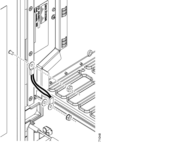
Step 1
Step 2
Figure 2-1 Installing the Door Ground Strap Retrofit Kit
Step 3
a.
b.
c.
Note
Step 4
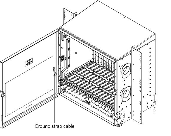
Step 5
Figure 2-2 shows the shelf assembly with the front door and ground strap installed.
Figure 2-2 Shelf Assembly with Door Ground Strap Retrofit Kit Installed
Step 6
Note
Stop. You have completed this procedure.
![]()
![]()
![]()
![]()
![]()
![]()
![]()
![]()
Posted: Mon Nov 12 00:15:14 PST 2007
All contents are Copyright © 1992--2007 Cisco Systems, Inc. All rights reserved.
Important Notices and Privacy Statement.