|
|

Table Of Contents
NTP-124 Provision a Point-to-Point Network
DLP-213 Provision SONET DCC Terminations
DLP-214 Change the Service State for a Port
NTP-125 Point-to-Point Network Acceptance Test
DLP-215 TCC+ Active/Standby Switch Test
DLP-216 Cross-Connect Card Active/Standby Switch Test
DLP-88 Optical 1+1 Protection Test
NTP-38 Provision a Linear ADM Network
NTP-39 Linear ADM Network Acceptance Test
NTP-42 Two-Fiber BLSR Acceptance Test
DLP-217 BLSR Exercise Ring Test
NTP-43 Four-Fiber BLSR Acceptance Test
DLP-92 Four-Fiber BLSR Exercise Span Test
DLP-93 Four-Fiber BLSR Span Switching Test
DLP-94 UPSR Protection Switching Test
NTP-46 Subtend a UPSR from a BLSR
NTP-47 Subtend a BLSR from a UPSR
NTP-48 Subtend a BLSR from a BLSR
Turn Up Network
This chapter explains how to turn up and test Cisco ONS 15454s network, including point-to-point networks, linear add drop multiplexers (ADMs), unidirectional path switched rings (UPSRs), and bidirectional line switched rings (BLSRs).
Before You Begin
This section lists the chapter procedures (NTPs). Turn to a procedure for applicable tasks (DLPs).
1.
NTP-35 Verify Node Turn Up—Complete this procedure before beginning network turn up.
2.
3.
4.
5.
6.
7.
8.
9.
10.
11.
12.
13.
14.
15.
NTP-35 Verify Node Turn Up
Step 1
Step 2
Step 3
•
•
Step 4
Step 5
Step 6
Step 7
Step 8
Step 9
Step 10
NTP-124 Provision a Point-to-Point Network
Step 1
Step 2
Step 3
Step 4
Step 5
Note
Note
Step 6
Step 7
DLP-213 Provision SONET DCC Terminations
Step 1
Step 2
Step 3
Step 4
Note
Step 5
Step 6
Step 7
Note
Step 8
DLP-214 Change the Service State for a Port
Note
Step 1
Step 2
Step 3
Step 4
•
•
•
•
Step 5
Step 6
Step 7
Step 8
NTP-125 Point-to-Point Network Acceptance Test
Step 1
Step 2
Step 3
Step 4
Step 5
Step 6
Step 7
Step 8
•
•
Step 9
•
•
•
Step 10
Step 11
Step 12
a.
b.
Step 13
Step 14
Step 15
Step 16
Step 17
Step 18
Step 19
Step 20
Step 21
Step 22
Step 23
Step 24
Step 25
After all tests are successfully completed and no alarms exist in the network, the network is ready for service application.
DLP-215 TCC+ Active/Standby Switch Test
Step 1
Step 2
Step 3
Step 4
Step 5
Step 6
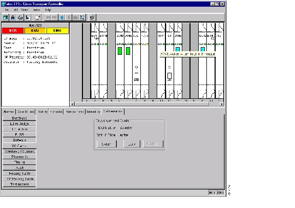
Figure 5-1 Resetting the active TCC+
Step 7
Step 8
Step 9
•
•
Step 10
Step 11
Step 12
Step 13
DLP-216 Cross-Connect Card Active/Standby Switch Test
Step 1
Step 2
Step 3
Step 4
Step 5
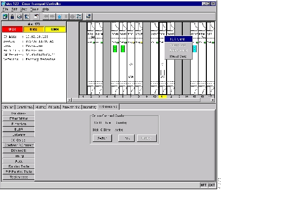
Figure 5-2 Performing a cross-connect card switch
Step 6
Step 7
Step 8
Step 9
Step 10
Step 11
Step 12
Step 13
Step 14
DLP-88 Optical 1+1 Protection Test
Purpose
This task verifies a 1+1 protection group will switch traffic properly.
Tools/Equipment
The test set specified by the acceptance test procedure
Prerequisite Procedures
DLP-60 Log into CTC; a test circuit created as part of the topology acceptance test
Required/As Needed
Required
Onsite/Remote
Onsite
Security Level
Provisioning or higher
Step 1
Step 2
Step 3
Step 4
Step 5
Step 6
Step 7
Step 8
Step 9
Protect port - Protect/Active [FORCE_SWITCH_TO_PROTECT] [PORT STATE]
Working port - Working/Standby [FORCE_SWITCH_TO_PROTECT], [PORT STATE]
Step 10
Step 11
Step 12
Step 13
Step 14
Step 15
Protect port - Protect/Active [FORCE_SWITCH_TO_WORKING], [PORT STATE]
Working port - Working/Standby [FORCE_SWITCH_TO_WORKING], [PORT STATE]
Step 16
Step 17
Step 18
Step 19
•
•
Step 20
NTP-38 Provision a Linear ADM Network
Step 1
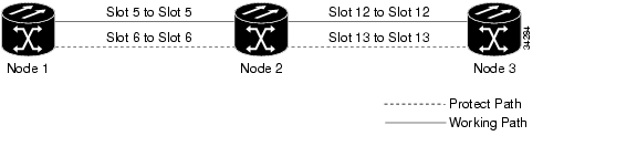
Figure 5-3 shows three ONS 15454s in a linear ADM configuration. In this example, working traffic flows from Slot 5/Node 1 to Slot 5/Node 2, and from Slot 12/Node 2 to Slot 12/Node 3. Slots 6 and 13 contain the protect OC-N cards. Slots 5 and 6 and Slots 12 and 13 are in 1+1 protection.
Figure 5-3 A linear ADM configuration
Step 2
Step 3
Step 4
Step 5
Note
Note
Step 6
Step 7
NTP-39 Linear ADM Network Acceptance Test
Step 1
Step 2
Step 3
Step 4
Step 5
Step 6
Step 7
Step 8
•
•
Step 9
•
•
•
Step 10
Step 11
Step 12
a.
b.
Step 13
Step 14
Step 15
Step 16
Step 17
Step 18
Step 19
Step 20
Step 21
Step 22
Step 23
After all tests are successfully completed and no alarms exist in the network, the network is ready for service application.
NTP-40 Provision BLSR Nodes
Step 1
•
•
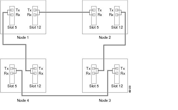
Figure 5-4 Four-node, two-fiber BLSR fiber connection example
Figure 5-5 Four-node, four-fiber BLSR fiber connection example
Step 2
Step 3
Note
Step 4
Step 5
Step 6
Step 7
DLP-89 Remap the K3 Byte
Caution
Step 1
Step 2
Step 3
Step 4
Step 5
Step 6
Step 7
NTP-126 Create a BLSR
Step 1
Step 2
Step 3
Step 4
Step 5
•
•
Note
•
•
For four-fiber BLSRs only, complete the following:
•
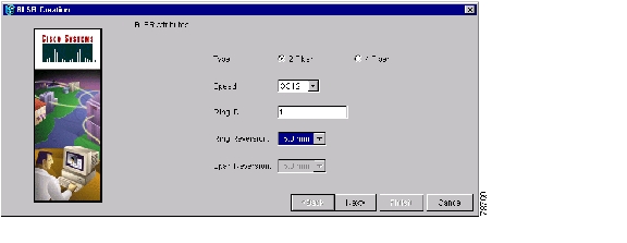
Figure 5-6 Setting BLSR properties
Step 6
a.
b.
c.
d.
Step 7
Step 8
Step 9
a.
b.
c.
d.
Note
Step 10
•
•
Step 11
NTP-42 Two-Fiber BLSR Acceptance Test
Note
Step 1
Step 2
Step 3
Step 4
Step 5
Step 6
Step 7
Step 8
Step 9
•
•
Step 10
•
•
•
Step 11
Step 12
Step 13
a.
b.
Step 14
Step 15
Step 16
Step 17
Although a service interruption under 60 ms may occur, the test circuit should continue to work before, during, and after the switches. If the circuit stops working, do not continue. Contact your next level of support.
Step 18
Step 19
Step 20
Step 21
Step 22
Step 23
After all tests are successfully completed and no alarms exist in the network, the network is ready for service application. Continue with "Create Circuits and VT Tunnels."
DLP-217 BLSR Exercise Ring Test
Step 1
Step 2
Step 3
Step 4
Note
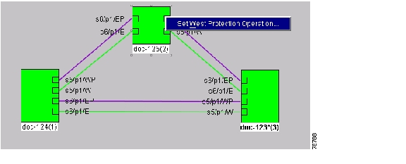
Figure 5-7 Invoking a protection operation on a three-node BLSR
Step 5
Step 6
On the network graphic, an E is displayed on the working BLSR channel where you invoked the protection switch. The E will display for 10-15 seconds, then disappear.
Step 7
Step 8
Step 9
Step 10
Step 11
DLP-91 BLSR Ring Switch Test
Step 1
Step 2
Step 3
Step 4
Note
Step 5
Step 6
On the network graphic, an F is displayed on the working BLSR channel where you invoked the protection switch. The BLSR span lines turn purple where the force was invoked, and all span lines between other BLSR nodes turn green.
Step 7
Step 8
Step 9
Step 10
Step 11
Step 12
Step 13
On the network graphic, the F indicating the force ring switch is removed and the span lines between BLSR nodes will be purple and green. The span lines may take a few moments to change color.
Step 14
Step 15
Step 16
On the network graphic, an F is displayed on the working BLSR channel where you invoked the force ring switch. The BLSR span lines are purple where the force was invoked, and all span lines between other BLSR nodes are green. The span lines may take a few moments to change color.
Step 17
Step 18
Step 19
Step 20
Step 21
Step 22
Step 23
On the network graphic, the F indicating the force ring switch is removed and the span lines between BLSR nodes will be purple and green. The span lines may take a few moments to change color.
Step 24
Step 25
NTP-43 Four-Fiber BLSR Acceptance Test
Note
Step 1
Step 2
Step 3
Step 4
Step 5
Step 6
Step 7
Step 8
Step 9
Step 10
•
•
Step 11
•
•
•
Step 12
Step 13
Step 14
a.
b.
Step 15
Step 16
Step 17
Step 18
Step 19
Step 20
Step 21
Step 22
Step 23
Step 24
Step 25
Step 26
After all tests are successfully completed and no alarms exist in the network, the network is ready for service application. Continue with "Create Circuits and VT Tunnels."
DLP-92 Four-Fiber BLSR Exercise Span Test
Purpose
This task exercises a four-fiber BLSR span.
Tools/Equipment
None
Prerequisite Procedures
Required/As Needed
Required
Onsite/Remote
Onsite
Security Level
Provisioning or higher
Step 1
Step 2
Step 3
Step 4
a.
Note
b.
c.
On the network graphic, an E is displayed on the working BLSR channel where you invoked the protection switch. The E will display for 10-15 seconds, then disappear.
Step 5
Step 6
Step 7
Step 8
a.
b.
c.
On the network graphic, an E is displayed on the working BLSR channel where you invoked the protection switch. The E will display for 10-15 seconds, then disappear.
Step 9
Step 10
Step 11
Step 12
Step 13
Step 14
DLP-93 Four-Fiber BLSR Span Switching Test
Step 1
Step 2
Step 3
Step 4
Step 5
a.
Note
b.
c.
On the network graphic, an F is displayed on the working BLSR channel where you invoked the protection switch. The BLSR span lines turn purple where the force was invoked, and all span lines between other BLSR nodes turn green.
Step 6
Step 7
Step 8
Step 9
Step 10
a.
b.
c.
On the network graphic, the F indicating the force span switch is removed and the span lines between BLSR nodes will be purple and green. The span lines may take a few moments to change color.
Step 11
a.
b.
c.
On the network graphic, an F is displayed on the working BLSR channel where you invoked the force ring switch. The BLSR span lines are purple where the force was invoked, and all span lines between other BLSR nodes are green. The span lines may take a few moments to change color.
Step 12
Step 13
Step 14
Step 15
Step 16
a.
b.
c.
On the network graphic, the F indicating the force ring switch is removed and the span lines between BLSR nodes will be purple and green. The span lines may take a few moments to change color.
Step 17
Step 18
NTP-44 Provision UPSR Nodes
Step 1
Figure 5-8 UPSR fiber connection example
Step 2
Step 3
Note
Step 4
Step 5
NTP-45 UPSR Acceptance Test
Step 1
Step 2
Step 3
Step 4
Step 5
Step 6
Step 7
Step 8
•
•
Step 9
•
•
•
Step 10
Step 11
a.
b.
Step 12
a.
b.
Step 13
Step 14
Step 15
Step 16
Although a service interruption under 60 ms may occur, the test circuit should continue to work before, during, and after the switches. If the circuit stops working, do not continue. Contact your next level of support.
Step 17
Step 18
Step 19
Although a service interruption under 60 ms may occur, the test circuit should continue to work before, during, and after the switches. If the circuit stops working, do not continue. Contact your next level of support.
Step 20
Step 21
Although a service interruption under 60 ms may occur, the test circuit should continue to work before, during, and after the switches. If the circuit stops working, do not continue. Contact your next level of support.
Step 22
Step 23
Step 24
Step 25
Step 26
Step 27
After all tests are successfully completed and no alarms exist in the network, the network is ready for service application. Continue with "Create Circuits and VT Tunnels."
DLP-94 UPSR Protection Switching Test
Step 1
Step 2
The Circuits on Span dialog box displays the UPSR circuits, including circuit names, location, and a color code showing which circuits are active on the span.
Step 3
Step 4
Step 5
On the Circuits on Span dialog box, the Switch State for all circuits is FORCE. Unprotected circuits will not switch.
Step 6
Step 7
Step 8
On the Circuits on Span window, the Switch State for all UPSR circuits is CLEAR.
NTP-46 Subtend a UPSR from a BLSR
Purpose
Use this procedure to subtend a UPSR from an existing BLSR.
Tools/Equipment
One BLSR node must have OC-N cards and fibers to carry the UPSR.
Prerequisite Procedures
NTP-42 Two-Fiber BLSR Acceptance Test or
NTP-43 Four-Fiber BLSR Acceptance TestRequired/As Needed
As needed
Onsite/Remote
Onsite
Security Level
Provisioning or higher
Step 1
Step 2
Step 3
Step 4
Step 5
Step 6
Step 7
Step 8
Figure 5-9 A UPSR subtending from a BLSR
Step 9
NTP-47 Subtend a BLSR from a UPSR
Step 1
Step 2
Step 3
Step 4
Step 5
a.
b.
Step 6
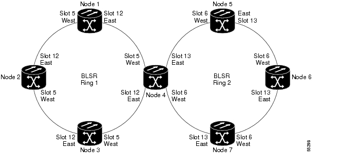
NTP-48 Subtend a BLSR from a BLSR
Note
Step 1
Step 2
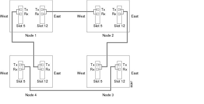
Figure 5-10 shows two BLSRs shared by one ONS 15454. Ring 1 runs on Nodes 1, 2, 3, and 4. Ring 2 runs on Nodes 4, 5, 6, and 7, and represents the subtending ring added by this procedure. Two BLSR rings, Ring 1 and Ring 2, are provisioned on Node 4. Ring 1 uses cards in Slots 5 and 12, and Ring 2 uses cards in Slots 6 and 13.
Figure 5-10 A BLSR subtending from a BLSR
Step 3
Step 4
Step 5
Step 6
Step 7
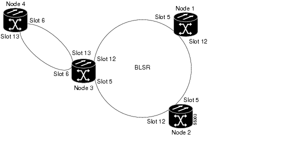
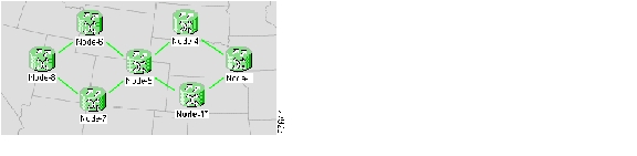
Figure 5-11 shows an example of two subtending BLSRs.
Figure 5-11 Viewing subtending BLSRs on the network map
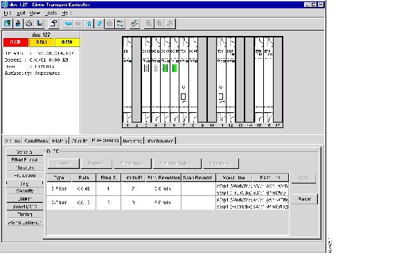
Figure 5-12 shows the Ring subtab for Node 5, which is the node that carries the two rings.
Figure 5-12 Configuring two BLSRs on the same node
Step 8
NTP-49 Create a DCC Tunnel
Note
Step 1
Step 2
Step 3
Step 4
Step 5
•
•
–
–
•
•
•
•
–
–
–
–
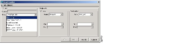
DCC options are not displayed if they are used by the ONS 15454 (DCC1) or other tunnels.
Figure 5-13 Provisioning a DCC tunnel
Step 6
Step 7
![]()
![]()
![]()
![]()
![]()
![]()
![]()
![]()
Posted: Fri Feb 22 16:16:07 PST 2008
All contents are Copyright © 1992--2008 Cisco Systems, Inc. All rights reserved.
Important Notices and Privacy Statement.