|
|

Table Of Contents
Connect the PC and Log into the GUI
NTP-21 Set Up Computer for CTC
DLP-47 Run the CTC Installation Wizard for Windows
DLP-48 Run the CTC Installation Wizard for UNIX
DLP-49 Set Up the Java Runtime Environment for UNIX
NTP-22 Set Up CTC Computer to Connect to the ONS 15454
DLP-51 Set Up a Windows PC for Craft Connection to an ONS 15454 Using DHCP
DLP-52 Set Up a Windows PC for Craft Connection to an ONS 15454 Using Automatic Host Detection
DLP-53 Set Up a Solaris Workstation for a Craft Connection to an ONS 15454
DLP-55 Set Up a Computer for a Corporate LAN Connection
DLP-56 Disable Proxy Service Using Internet Explorer (Windows)
DLP-57 Disable Proxy Service Using Netscape (Windows and UNIX)
DLP-58 Provision Remote Access to the ONS 15454
NTP-23 Log into the ONS 15454 GUI
DLP-59 Connect Computer to the ONS 15454
DLP-61 Create Login Node Groups
DLP-62 Add a Node to the Current Session or Login Group
Connect the PC and Log into the GUI
This chapter explains how to connect PCs and workstations to the Cisco ONS 15454 and how to log into Cisco Transport Controller (CTC) software, the Cisco ONS 15454 OAM&P user interface.
Before You Begin
This section lists the chapter procedures (NTPs). Turn to a procedure for applicable tasks (DLPs).
1.
NTP-21 Set Up Computer for CTC—Complete this procedure if your PC or workstation has never been connected to an ONS 15454.
2.
3.
NTP-21 Set Up Computer for CTC
Step 1
Step 2
Step 3
Step 4
DLP-47 Run the CTC Installation Wizard for Windows
Step 1
•
•
•
•
Note
Step 2
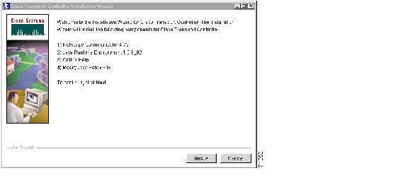
The Cisco Transport Controller Installation Wizard displays the components that will be installed on your computer ( Figure 3-1).
Figure 3-1 Starting the Cisco Transport Controller Installation Wizard
Step 3
Step 4
Step 5
Step 6
Step 7
Step 8
Step 9
Step 10
Step 11
An Installation Issues dialog box is displayed.
Step 12
Step 13
a.
b.
c.
Note
d.
e.
f.
g.
h.
i.
Step 14
Step 15
Step 16
a.
b.
c.
When JRE installation is complete, the Cisco Transport Controller Installation Wizard dialog box is displayed.
Step 17
Step 18
•
•
Step 19
Step 20
a.
b.
Step 21
Step 22
DLP-48 Run the CTC Installation Wizard for UNIX
Step 1
•
•
•
Note
Step 2
cd /cdrom/cdrom0/
Step 3
./setup.bat
The Cisco Transport Controller Installation Wizard displays the components that will be installed on your computer ( Figure 3-1):
•
•
•
•
Step 4
Step 5
Step 6
Step 7
Step 8
Step 9
Step 10
Step 11
Step 12
a.
b.
c.
d.
e.
f.
g.
Step 13
Step 14
a.
b.
c.
When JRE installation is complete, the Cisco Transport Controller Installation Wizard dialog box is displayed.
Step 15
Step 16
•
•
Step 17
Note
Step 18
Note
DLP-49 Set Up the Java Runtime Environment for UNIX
Note
Note
Step 1
a.
setenv JRE [JRE path]
setenv NETSCAPE [Netscape path]
setenv NPX_PLUGIN_PATH $JRE/j2re1_3_1_02/plugin/sparc/ns4
set path = ( /usr/openwin/bin $NETSCAPE $path )
b.
JRE=[your JRE path]
NETSCAPE=[your Netscape path]
NPX_PLUGIN_PATH=$JRE/j2re1_3_1_02/plugin/sparc/ns4
PATH=/usr/openwin/bin:$NETSCAPE:$PATH
export JRE NPX_PLUGIN_PATH PATH
Step 2
a.
[JRE path]/j2re1_3_0_02/bin/ControlPanel
b.
c.
[JRE path]/j2re1_3_1_02
d.
Note
NTP-22 Set Up CTC Computer to Connect to the ONS 15454
Step 1
Note
Step 2
Step 3
Step 4
Step 5
Table 3-2 ONS 15454 Craft Connection Options
•
Complete this task if:
•
•
•
•
•
Complete this task if:
•
•
•
•
Complete this task if:
•
•
Step 6
DLP-50 Set Up a Windows PC for Craft Connection to an ONS 15454 on the Same Subnet Using Static IP Addresses
Step 1
a.
b.
c.
Step 2
a.
b.
c.
d.
e.
f.
g.
h.
i.
j.
k.
l.
m.
n.
Step 3
a.
b.
c.
d.
e.
f.
g.
h.
i.
j.
k.
l.
m.
n.
Step 4
a.
b.
c.
d.
e.
f.
g.
h.
i.
j.
Step 5
a.
Note
b.
c.
d.
e.
f.
g.
h.
i.
Step 6
DLP-51 Set Up a Windows PC for Craft Connection to an ONS 15454 Using DHCP
Purpose
Use this task to set up your computer for craft connection to the ONS 15454 using DHCP (dynamic host configuration protocol).
Tools/Equipment
Straight-through (CAT-5) LAN cable
Prerequisite Procedures
NTP-21 Set Up Computer for CTC
Required/As Needed
As needed
Onsite/Remote
Onsite
Caution
Step 1
a.
b.
c.
Step 2
a.
b.
c.
d.
e.
f.
g.
h.
i.
Step 3
a.
b.
c.
d.
e.
f.
g.
h.
Step 4
a.
b.
c.
d.
e.
f.
g.
Step 5
a.
Note
b.
c.
d.
e.
f.
g.
h.
Step 6
DLP-52 Set Up a Windows PC for Craft Connection to an ONS 15454 Using Automatic Host Detection
Note
Step 1
a.
Note
b.
c.
Step 2
a.
b.
c.
d.
e.
f.
g.
h.
i.
j.
k.
l.
m.
n.
Step 3
a.
b.
c.
d.
e.
f.
g.
h.
i.
j.
k.
l.
m.
n.
Step 4
a.
b.
c.
d.
e.
f.
g.
h.
i.
j.
Step 5
a.
Note
b.
c.
d.
e.
f.
g.
h.
i.
Step 6
DLP-53 Set Up a Solaris Workstation for a Craft Connection to an ONS 15454
Purpose
Use this task to set up a Solaris workstation for a craft connection to the ONS 15454.
Tools/Equipment
None
Prerequisite Procedures
Required/As Needed
As needed
Onsite/Remote
Onsite
Step 1
Step 2
# ifconfig <device>
For example: # ifconfig hme1
a.
b.
# if config <device> plumb
For example: ifconfig hme1 plumb
Step 3
#ifconfig <interface> <ip address> netmask <netmask> up
For example: #ifconfig hme0 10.20.30.40 netmask 255.255.255.0 up
Note
Step 4
a.
b.
c.
ping [ONS 15454 IP address]
For example, you would type "ping 192.168.1.1" to connect to an ONS 15454 with default IP address 192.168.1.1. If your workstation is connected to the ONS 15454, an "[IP address] is alive" message displays.
Note
d.
#ndd -set /dev/<device> instance 0
#ndd -get /dev/<device> link_status
For example:
#ndd -set /dev/hme instance 0
#ndd -get /dev/hme link_status
The result of 1 means the link is up. The result of 0 means the link is down.
Note
Step 5
DLP-55 Set Up a Computer for a Corporate LAN Connection
Purpose
Use this task to set up your computer to access the ONS 15454 through a corporate LAN.
Tools/Equipment
None
Prerequisite Procedures
Required/As Needed
As needed
Onsite/Remote
Onsite or remote
Step 1
•
•
Step 2
•
•
DLP-56 Disable Proxy Service Using Internet Explorer (Windows)
Step 1
Note
Step 2
Step 3
Step 4
•
•
Step 5
DLP-57 Disable Proxy Service Using Netscape (Windows and UNIX)
Step 1
Step 2
Step 3
Step 4
•
or
•
Step 5
DLP-58 Provision Remote Access to the ONS 15454
Step 1
Step 2
•
•
•
Note
Step 3
NTP-23 Log into the ONS 15454 GUI
Purpose
Use this procedure to log into the Cisco Transport Controller, the graphical user interface software used to manage the ONS 15454. This procedure includes optional node login tasks.
Tools/Equipment
None
Prerequisite Procedures
NTP-21 Set Up Computer for CTC
Required/As Needed
Required to access the Cisco Transport Controller
Onsite/Remote
Onsite or remote
Security Level
Retrieve or higher
Step 1
Step 2
Note
Step 3
Step 4
DLP-59 Connect Computer to the ONS 15454
Purpose
Use this task to connect a CTC computer to the ONS 15454.
Tools/Equipment
Straight-through (CAT-5) LAN cable
Prerequisite Procedures
NTP-21 Set Up Computer for CTC
Required/As Needed
Required to access the Cisco Transport Controller
Onsite/Remote
Onsite or remote
Step 1
•
•
Note
Step 2
Step 3
DLP-60 Log into CTC
Purpose
Use this task to log into the Cisco Transport Controller, the graphical user interface software used to manage the ONS 15454.
Tools/Equipment
None
Prerequisite Procedures
NTP-21 Set Up Computer for CTC
Required/As Needed
Required
Onsite/Remote
Onsite or remote
Security Level
Retrieve or higher
Note
Step 1
Step 2
Note
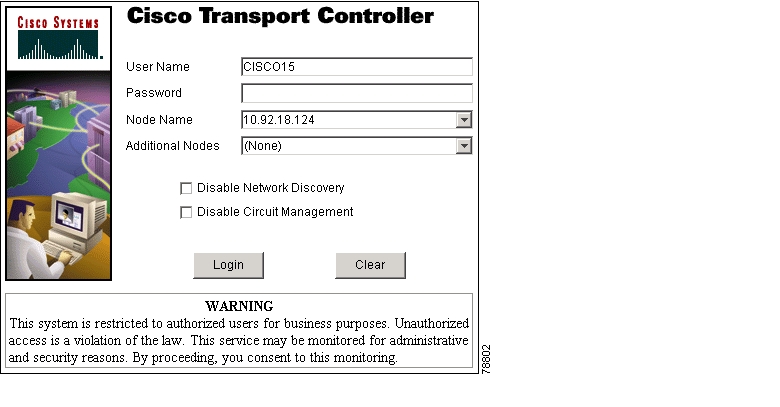
A Java Console window displays the CTC file download status. The web browser displays information about your Java and system environments. If this is the first login, CTC caching messages display while CTC files are downloaded to your computer. The first time you connect to an ONS 15454, this process can take several minutes. After the download, the CTC Login dialog box displays ( Figure 3-2).
Figure 3-2 Logging into CTC
Step 3
Note
Step 4
•
•
Note
•
•
Step 5
If login is successful, the CTC window displays. From here, you can navigate to other CTC views to provision and manage the ONS 15454. If you need to perform the initial shelf turn up, see "Turn Up Node." If login problems occur, refer to the Cisco ONS 15454 Troubleshooting Guide.
DLP-61 Create Login Node Groups
Purpose
Create a login node group to display ONS 15454s that have an IP connection but not a DCC connection to the login node.
Tools/Equipment
None
Prerequisite Procedures
NTP-21 Set Up Computer for CTC
Required/As Needed
As needed
Onsite/Remote
Onsite or remote
Security Level
Provisioning or higher
Step 1
Step 2
Step 3
Step 4
Step 5
Step 6
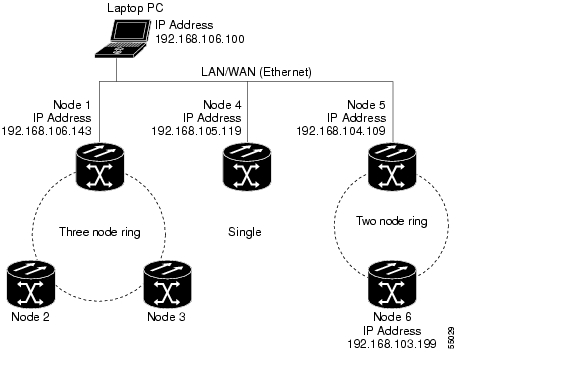
The next time you log into an ONS 15454, the login node group will be available in the Additional Nodes list of the Login dialog box. For example, in Figure 3-3, a login node group, "Test Group," is created and the IP addresses for Nodes 1, 4, and 5. During login, if you select Test Group under Additional Nodes and Disable Network Discovery is not selected, all nodes in the figure are displayed. If Test Group and Disable Network Discovery are both selected, Nodes 1, 4, and 5 will be displayed. You can create as many login groups as you need. The groups are stored in the CTC preferences file and are not visible to other users.
Figure 3-3 A login node group
DLP-62 Add a Node to the Current Session or Login Group
Step 1
Step 2
Step 3
Step 4
Note
Step 5
After a few seconds, the new node will be displayed on the network view map.
![]()
![]()
![]()
![]()
![]()
![]()
![]()
![]()
Posted: Fri Feb 22 14:09:40 PST 2008
All contents are Copyright © 1992--2008 Cisco Systems, Inc. All rights reserved.
Important Notices and Privacy Statement.