|
|

Table Of Contents
NTP-81 Change Node Management Information
DLP-140 Change the Node Name, Date, Time, and Contact Information
DLP-265 Change the Login Legal Disclaimer
NTP-82 Change CTC Network Access
DLP-141 Change IP Address, Subnet Mask, Default Router, and Network Defaults
NTP-83 Customize the CTC Network View
DLP-145 Change the Network View Background Color
DLP-146 Change the Default Network View Map
DLP-147 Apply a Custom Network View Background Map
NTP-84 Modify or Delete Card Protection Settings
DLP-150 Modify a 1:1 Protection Group
DLP-152 Modify a 1:N Protection Group
DLP-154 Modify a 1+1 Protection Group
DLP-155 Delete a Protection Group
DLP-156 Delete a SONET DCC Termination or Tunnel
DLP-157 Change the Node Timing Source
NTP-86 Modify Users and Change Security
DLP-158 Change User and Security Settings - Single Node
DLP-159 Delete User - Single Node
DLP-160 Change User and Security Settings - Multiple Nodes
DLP-161 Delete User - Multiple Nodes
DLP-162 Modify SNMP Trap Destination
DLP-163 Delete SNMP Trap Destination
DLP-164 Delete Ethernet RMON Alarm Thresholds
Change Node Settings
This chapter explains how to modify node provisioning. To provision a new node, see "Turn Up Node." To change default network element settings and to view a list of those settings, see "Network Element Defaults."
Before You Begin
Before performing the following procedures, investigate all alarms and clear any trouble conditions. Refer to the Cisco ONS 15454 Troubleshooting Guide as necessary.
This section lists the chapter procedures (NTPs). Turn to a procedure for applicable tasks (DLPs).
1.
NTP-81 Change Node Management Information—As needed, complete this procedure to change node name, contact information, latitude, longitude, date, and time.
2.
3.
4.
5.
6.
7.
NTP-81 Change Node Management Information
Step 1
Step 2
Step 3
Step 4
Note
Step 5
Step 6
DLP-140 Change the Node Name, Date, Time, and Contact Information
Step 1
Step 2
•
•
•
•
•
Note
•
•
•
•
•
See the "NTP-26 Set Up CTC Network Access" procedure for detailed field descriptions.
Note
Step 3
Note
Step 4
DLP-265 Change the Login Legal Disclaimer
Step 1
Step 2
•
•
•
•
•
•
•
•
•
•
•
•
•
Step 3
Step 4
Step 5
NTP-82 Change CTC Network Access
The following procedures explains how to change essential ONS 15454 networking information. Additional ONS 15454 networking information and procedures, including IP addressing examples, static route scenarios, Open Shortest Path First (OSPF) protocol, and routing information protocol options are provided in the IP Networking section of the Cisco ONS 15454 Reference Manual.
Step 1
Step 2
Step 3
•
•
•
•
Step 4
DLP-141 Change IP Address, Subnet Mask, Default Router, and Network Defaults
Step 1
Step 2
•
•
•
•
•
•
•
See the "DLP-64 Set the IP Address, Default Router, and Network Mask Using the LCD" task for detailed field descriptions.
Note
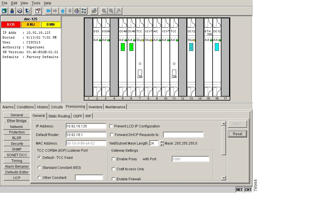
Figure 10-1 Changing general network information
Step 3
Step 4
Both ONS 15454 TCC+ cards will reboot, one at a time. Confirm that the changes appear.
Note
Step 5
DLP-142 Modify a Static Route
Step 1
Step 2
Step 3
Step 4
Step 5
•
•
•
Step 6
Note
Step 7
DLP-143 Delete a Static Route
Step 1
Step 2
Step 3
Step 4
Step 5
Step 6
DLP-144 Disable OSPF
Step 1
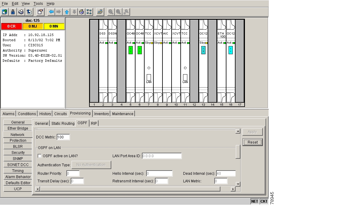
Figure 10-2 Disabling OSPF on the ONS 15454
Step 2
Note
Step 3
Note
Step 4
Note
NTP-83 Customize the CTC Network View
Step 1
Step 2
•
•
•
DLP-145 Change the Network View Background Color
Note
Step 1
Step 2
Step 3
Step 4
Step 5
DLP-146 Change the Default Network View Map
Step 1
Step 2
Step 3
Step 4
Step 5
Step 6
Step 7
Step 8
Step 9
Step 10
DLP-147 Apply a Custom Network View Background Map
Note
Step 1
Step 2
Step 3
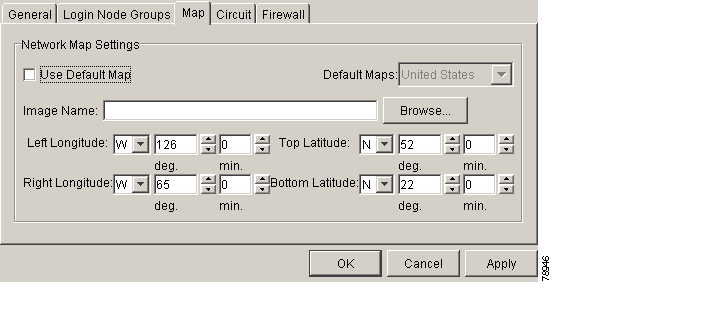
Figure 10-3 Changing the CTC background image
Step 4
Step 5
Step 6
Tip
Step 7
Step 8
Step 9
Step 10
Step 11
Step 12
Step 13
DLP-148 Create Domain Icons
Note
Step 1
Step 2
Step 3
Step 4
Step 5
DLP-149 Manage Domain Icons
Note
Step 1
Step 2
Step 3
NTP-84 Modify or Delete Card Protection Settings
Caution
Step 1
Step 2
Step 3
•
•
•
•
Step 4
DLP-150 Modify a 1:1 Protection Group
Step 1
Step 2
Step 3
•
•
•
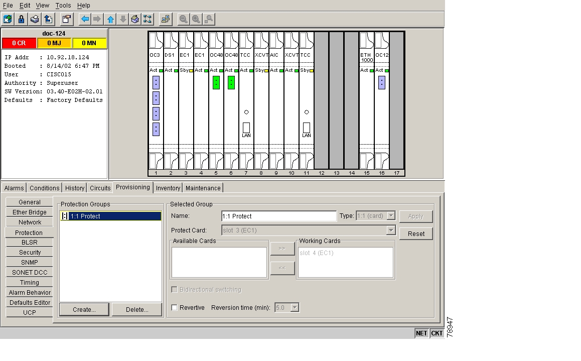
Figure 10-4 Modifying a 1:1 protection group
Step 4
Note
Step 5
Note
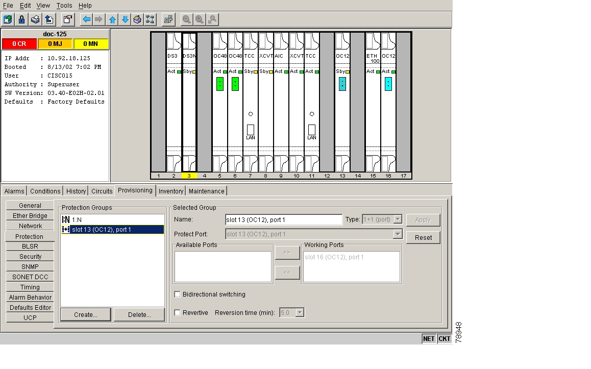
DLP-152 Modify a 1:N Protection Group
Step 1
Step 2
Step 3
Step 4
•
•
•
•
See the "DLP-72 Create a 1:N Protection Group" task for field descriptions.
Figure 10-5 Modifying a 1:N protection group
Step 5
Note
Step 6
Note
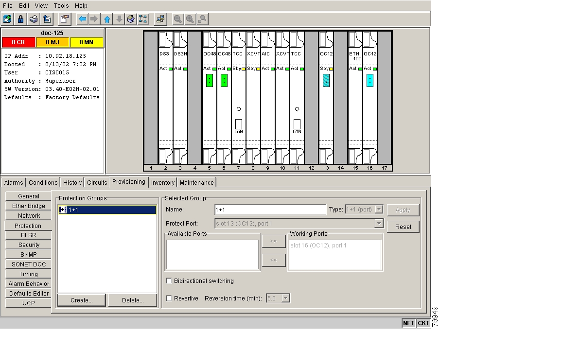
DLP-154 Modify a 1+1 Protection Group
Step 1
Step 2
Step 3
•
•
•
•
See the "DLP-73 Create a 1+1 Protection Group" task for field descriptions.
Figure 10-6 Modifying a 1+1 protection group
Step 4
Note
Step 5
Note
DLP-155 Delete a Protection Group
Step 1
Step 2
Step 3
Step 4
Step 5
DLP-156 Delete a SONET DCC Termination or Tunnel
Note
Step 1
Step 2
Step 3
Step 4
Note
Step 5
Note
NTP-85 Change Node Timing
Step 1
Step 2
Step 3
Step 4
Caution
Step 5
Step 6
DLP-157 Change the Node Timing Source
Caution
Step 1
Step 2
•
Note
•
•
•
•
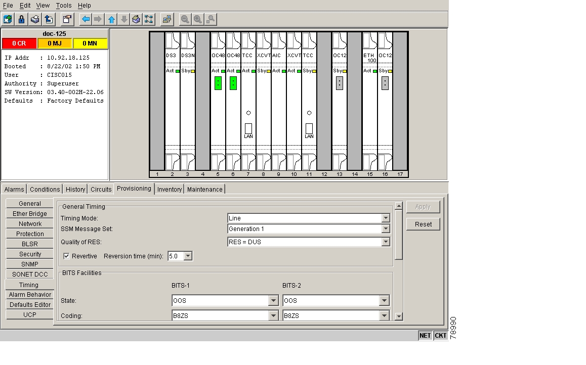
See the "DLP-69 Set Up External or Line Timing" task for field descriptions.
Step 3
Note
•
•
•
•
•
•
Step 4
Note
•
•
Figure 10-7 Modifying ONS 15454 timing
Step 5
Note
Step 6
Note
NTP-86 Modify Users and Change Security
The CISCO15 user provided with each ONS 15454 can be used to set up other ONS 15454 users. You can add up to 500 users to one ONS 15454. You can perform ONS 15454 user management tasks from network or node view. In network view, you can add, edit, or delete users from multiple nodes at one time. If you perform user management tasks in node view, you can only add, edit, or delete users from that node.
See the "NTP-30 Create Users and Assign Security" procedure for more information about adding users.
Step 1
Step 2
Step 3
•
•
•
•
Step 4
DLP-158 Change User and Security Settings - Single Node
Step 1
Step 2
Step 3
•
•
•
See the "NTP-30 Create Users and Assign Security" procedure for field descriptions.
Step 4
Note
Step 5
Note
DLP-159 Delete User - Single Node
Purpose
Use this task to delete an existing user from a single node.
Tools/Equipment
None
Prerequisite Procedures
Required/As Needed
As needed
Onsite/Remote
Onsite or remote
Security Level
Superuser
Step 1
Step 2
Step 3
Step 4
Note
Step 5
DLP-160 Change User and Security Settings - Multiple Nodes
Note
Step 1
Step 2
Step 3
Step 4
•
•
•
See the "DLP-75 Create a New User - Multiple Nodes" task for field descriptions.
Step 5
Step 6
Step 7
Note
Step 8
DLP-161 Delete User - Multiple Nodes
Note
Step 1
Step 2
Step 3
Step 4
Step 5
Step 6
Note
Step 7
NTP-87 Change SNMP Settings
Note
Step 1
Step 2
Step 3
•
•
•
Step 4
DLP-162 Modify SNMP Trap Destination
Step 1
Step 2
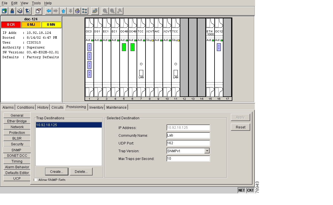
For a description of SNMP traps, see the Cisco ONS 15454 Reference Guide.
Step 3
Note
Note
Step 4
Refer to your NMS documentation to determine whether to use SNMP v1 or v2.
Step 5
Note
Step 6
Step 7
Note
Step 8
Figure 10-8 Viewing trap destinations
DLP-163 Delete SNMP Trap Destination
Purpose
Use this task to delete SNMP on an ONS 15454.
Tools/Equipment
None
Prerequisite Procedures
Required/As Needed
As needed
Onsite/Remote
Onsite or remote
Security Level
Provisioning or higher
Step 1
Step 2
Step 3
Step 4
Note
Step 5
DLP-164 Delete Ethernet RMON Alarm Thresholds
Step 1
Step 2
Step 3
Step 4
Step 5
Step 6
![]()
![]()
![]()
![]()
![]()
![]()
![]()
![]()
Posted: Fri Feb 22 14:14:39 PST 2008
All contents are Copyright © 1992--2008 Cisco Systems, Inc. All rights reserved.
Important Notices and Privacy Statement.