|
|

Table Of Contents
Install Cards and Fiber-Optic Cable
NTP-15 Install the Common Control Cards
DLP-37 Install the XC, XCVT, or XC10G Cards
DLP-38 Install the Alarm Interface Controller or Alarm Interface Controller-International Card
NTP-16 Install the Optical Cards
NTP-17 Install the Electrical Cards
NTP-18 Install the Ethernet Cards
DLP-40 Install Gigabit Interface Converters
NTP-116 Remove and Replace a Card
DLP-247 Change an Optical Card
NTP-19 Install the Fiber-Optic Cables
DLP-207 Install Fiber-Optic Cables on the LGX Interface
DLP-42 Install Fiber-Optic Cables on OC-N Cards
DLP-43 Install Fiber-Optic Cables for UPSR Configurations
DLP-44 Install Fiber-Optic Cables for BLSR Configurations
DLP-46 Route Fiber-Optic Cables
Install Cards and Fiber-Optic Cable
This chapter explains how to install the Cisco ONS 15454 cards and fiber-optic cable (fiber).
Before You Begin
This section lists the chapter procedures (NTPs). Turn to a procedure for applicable tasks (DLPs).
1.
Before beginning any procedure in this chapter, make sure you have completed the "NTP-13 Perform the Shelf Installation Acceptance Test" procedure on page 1-61
2.
3.
4.
5.
6.
7.
8.
9.
Warning
Caution
NTP-15 Install the Common Control Cards
Purpose
This procedure describes how to install the common control cards.
Tools/Equipment
TCC+ cards
XC/XCVT/XC10G (cross-connect) cards
AIC/AIC-I card
Prerequisite Procedures
"NTP-13 Perform the Shelf Installation Acceptance Test" procedure on page 1-61
Required/As Needed
Required
Onsite/Remote
Onsite
Security Level
Provisioning or higher
Warning
Caution
Note
When installing cards, let each card completely boot before installing the next card.
Step 1
Step 2
Step 3
Step 4
Step 5
Step 6
MS identifies a multispeed slot.
HS identifies a high-speed slot.
X indicates that a card is supported in the slot.
X* identifies 1:N cards that operate as normal DS1 or DS3 cards when installed in certain slots.
The XC10G card requires the ANSI shelf with high-speed fans.
MS identifies a multispeed slot.
HS identifies a high-speed slot.
X indicates that a card is supported in the slot.
X* identifies 1:N cards that operate as normal DS1 or DS3 cards when installed in certain slots.
DLP-36 Install the TCC+ Cards
Step 1
Step 2
Step 3
Note
If you insert a card into a slot provisioned for a different card, all LEDS turn off.
Step 4
a.
b.
c.
d.
e.
Note
Note
Tip
Step 5
Step 6
Step 7
Refer to the Cisco ONS 15454 Software Upgrade Guide or the "NTP-163 Restore the Node to Factory Configuration" procedure on page 15-11 to replace the software, or, to swap the TCC+, see the "NTP-116 Remove and Replace a Card" procedure.
Step 8
Step 9
Step 10
Note
Step 11
a.
b.
c.
d.
e.
Note
Note
Note
Step 12
Step 13
DLP-37 Install the XC, XCVT, or XC10G Cards
Note
Step 1
Step 2
Step 3
Step 4
Note
Step 5
1.
2.
3.
4.
5.
Note
Note
Note
Step 6
Step 7
Step 8
Note
Step 9
1.
2.
3.
4.
5.
Note
Note
Note
Step 10
Step 11
DLP-38 Install the Alarm Interface Controller or Alarm Interface Controller-International Card
Step 1
Step 2
Step 3
Step 4
Note
Step 5
•
•
•
Step 6
•
•
•
Note
Note
Note
Note
Step 7
NTP-16 Install the Optical Cards
Note
Warning
Caution
Warning
Warning
Warning
Note
Step 1
Install higher-capacity cards first; for example, install an OC-192 card before installing an OC-48 card. Let each card completely boot before installing the next card.
Step 2
Warning
Step 3
Step 4
Note
Step 5
1.
2.
3.
4.
Step 6
•
•
•
•
Step 7
Step 8
NTP-17 Install the Electrical Cards
Purpose
This procedure describes how to install the electrical cards (DS-1, DS-3, and EC1).
Tools/Equipment
Electrical cards
Prerequisite Procedures
NTP-15 Install the Common Control Cards
NTP-16 Install the Optical Cards (if applicable)
Required/As Needed
Required if the node will carry any electrical traffic
Onsite/Remote
Onsite
Security Level
Provisioning or higher
Warning
Caution
Note
Step 1
Step 2
Step 3
Step 4
Note
Step 5
1.
If the red FAIL LED does not illuminate, check the power.
2.
3.
4.
Note
Note
Step 6
NTP-18 Install the Ethernet Cards
Purpose
This procedure describes how to install the Ethernet cards.
Tools/Equipment
Ethernet cards
Prerequisite Procedures
NTP-15 Install the Common Control Cards
NTP-16 Install the Optical Cards (if applicable)
NTP-17 Install the Electrical Cards (if applicable)
Required/As Needed
Required if the node will carry Ethernet traffic
Onsite/Remote
Onsite
Warning
Caution
Warning
Warning
Step 1
Step 2
Note
Step 3
DLP-39 Install Ethernet Cards
Purpose
This task installs the Ethernet cards.
Tools/Equipment
Ethernet cards
Prerequisite Procedures
Required/As Needed
Required
Onsite/Remote
Onsite
Step 1
Step 2
Step 3
Note
Step 4
1.
2.
3.
4.
Note
Note
Step 5
DLP-40 Install Gigabit Interface Converters
Note
Step 1
Step 2
Step 3
Step 4
GBICs are hot-swappable and can therefore be installed/removed while the card/shelf assembly is powered and running.
Note
Figure 2-1 Installing a GBIC on an E1000-2 card
Step 5
The click indicates the GBIC is locked into the slot.
Warning
Warning
Step 6
Step 7
Step 8
NTP-116 Remove and Replace a Card
Step 1
Step 2
•
•
Step 3
a.
b.
Step 4
•
•
•
•
DLP-191 Delete a Card
Purpose
This task deletes a card from CTC.
Tools/Equipment
None
Prerequisite Procedures
Required/As Needed
As needed
Onsite/Remote
Both
Step 1
Step 2
You cannot delete a card if any of the following conditions apply:
•
•
•
•
•
•
Note
Step 3
DLP-247 Change an Optical Card
Caution
Step 1
Step 2
a.
b.
c.
d.
e.
f.
Step 3
Step 4
Step 5
a.
b.
Step 6
Step 7
NTP-115 Pre-Provision a Slot
Step 1
Step 2
Step 3
Note
NTP-19 Install the Fiber-Optic Cables
Note
Purpose
This procedure describes how to install fiber-optic cables on optical cards and Ethernet gigabit interface converters (GBIC).
Tools/Equipment
Fiber-optic cables
Fiber boot
Prerequisite Procedures
NTP-16 Install the Optical Cards
Required/As Needed
Required
Onsite/Remote
Onsite
Note
Caution
Warning
Warning
Warning
Warning
Caution
Note
Step 1
Step 2
Step 3
Step 4
Step 5
Step 6
Step 7
DLP-207 Install Fiber-Optic Cables on the LGX Interface
Purpose
This task installs fiber-optic cables on the Lightguide Cross Connect (LGX) interface in the Central Office.
Tools/Equipment
Fiber-optic cables
Prerequisite Procedures
NTP-16 Install the Optical Cards
Required/As Needed
Required
Onsite/Remote
Onsite
Note
Step 1
Step 2
Step 3
Step 4
DLP-42 Install Fiber-Optic Cables on OC-N Cards
Purpose
This task installs fiber-optic cables on optical (OC-N) cards.
Tools/Equipment
Fiber-optic cables
Prerequisite Procedures
NTP-16 Install the Optical Cards
NTP-112 Clean Fiber Connectors, page 15-21
DLP-207 Install Fiber-Optic Cables on the LGX Interface (as applicable)
Required/As Needed
Required
Onsite/Remote
Onsite
Note
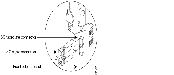
Step 1
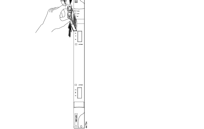
Figure 2-2 Installing fiber-optic cables
Note
Step 2
Step 3
Step 4
DLP-43 Install Fiber-Optic Cables for UPSR Configurations
Purpose
This task installs the fiber-optic cables to the east and west UPSR ports at each node. See "Turn Up Network" to provision and test UPSR configurations.
Tools/Equipment
Fiber-optic cables
Prerequisite Procedures
NTP-16 Install the Optical Cards
Required/As Needed
Required
Onsite/Remote
Onsite
Note
Note
Step 1
Step 2
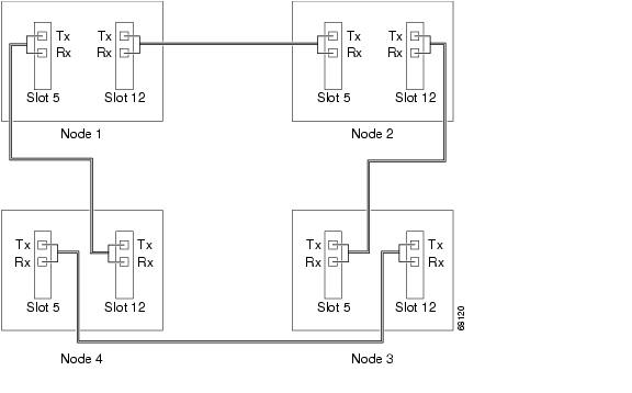
Figure 2-3 shows fiber connections for a four-node UPSR with trunk cards in Slot 5 (west) and Slot 12 (east).
Figure 2-3 Connecting fiber to a four-node UPSR
Step 3
DLP-44 Install Fiber-Optic Cables for BLSR Configurations
Purpose
This task installs the fiber-optics to the east and west BLSR ports at each node. See "Turn Up Network" to provision and test BLSR configurations.
Tools/Equipment
Fiber-optic cables
Prerequisite Procedures
NTP-16 Install the Optical Cards
Required/As Needed
Required for a BLSR configuration
Onsite/Remote
Onsite
Note
Note
Step 1
Step 2
Note
Step 3
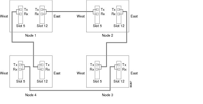
Figure 2-4 shows fiber connections for a two-fiber BLSR with trunk cards in Slot 5 (west) and Slot 12 (east).
Figure 2-4 Connecting fiber to a four-node, two-fiber BLSR
Figure 2-5 shows fiber connections for a four-fiber BLSR. Slot 5 (west) and Slot 12 (east) carry the working traffic. Slot 6 (west) and Slot 13 (east) carry the protect traffic.
Figure 2-5 Connecting fiber to a four-node, four-fiber BLSR
Step 4
DLP-45 Install the Fiber Boot
Purpose
This task installs the fiber boot.
Tools/Equipment
Fiber boot
Prerequisite Procedures
NTP-16 Install the Optical Cards
Required/As Needed
Required for all optical cards except the OC-192 and the OC-48 AS cards
Onsite/Remote
Onsite
Note
Step 1
Step 2
Step 3
Step 4
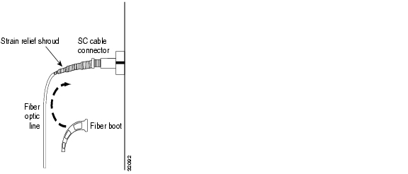
Figure 2-6 Attaching a fiber boot
Step 5
DLP-46 Route Fiber-Optic Cables
Purpose
This task describes how to route fiber-optic cables.
Tools/Equipment
None
Prerequisite Procedures
Cables to be routed must be installed
Required/As Needed
Required
Onsite/Remote
Onsite
Step 1
Step 2
GBICs do not have fiber clips; therefore, if you are routing optical cable from an E1000-2-G, E1000-2, or G1000-4 card, skip to Step 3.
Step 3
Step 4
Step 5
Step 6
NTP-20 Replace the Front Door
Step 1
Step 2
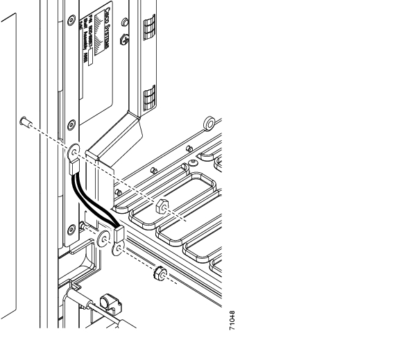
Figure 2-7 Installing the Door Ground Strap Retrofit Kit
Step 3
a.
b.
c.
Note
Step 4
Step 5
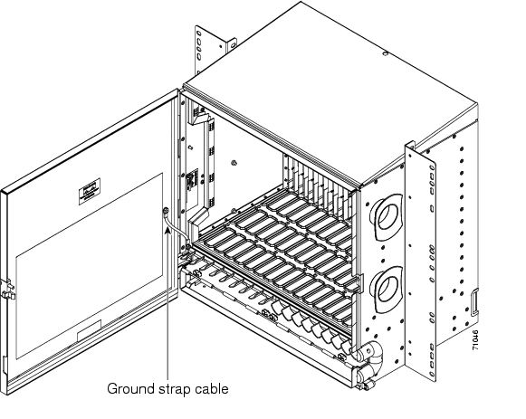
Figure 2-8 shows the shelf assembly with the front door and ground strap installed.
Figure 2-8 Shelf assembly with Door Ground Strap Retrofit Kit installed
Step 6
Note
Figure 2-9 The ONS 15454 front door
Step 7
![]()
![]()
![]()
![]()
![]()
![]()
![]()
![]()
Posted: Fri Feb 22 14:10:03 PST 2008
All contents are Copyright © 1992--2008 Cisco Systems, Inc. All rights reserved.
Important Notices and Privacy Statement.