|
|

Table Of Contents
NTP-80 Document Existing Provisioning
NTP-67 View Alarms, History, Events, and Conditions
DLP-111 Changing the Maximum Number of Session Entries for Alarm History
DLP-112 Display Alarms and Events Using Each Node's Timezone
DLP-113 View Events and Synchronize Alarms
NTP-68 Delete Cleared Alarms from Display
NTP-69 View Alarm-Affected Circuits
NTP-70 View Alarm Counts on the LCD for a Slot or Port
NTP-71 Create, Download, and Assign Alarm Severity Profiles
DLP-115 Create Alarm Severity Profiles
DLP-223 Download an Alarm Severity Profile
DLP-116 Apply Alarm Profiles to Ports
DLP-117 Apply Alarm Profiles to Cards and Nodes
DLP-118 Delete Alarm Severity Profiles
NTP-168 Enable, Modify, or Disable Alarm Severity Filtering
DLP-225 Enable Alarm Filtering
DLP-226 Modify Alarm and Condition Filtering Parameters
DLP-227 Disable Alarm Filtering
NTP-72 Suppress and Unsuppress Alarm Reporting
DLP-119 Suppress Alarm Reporting
DLP-120 Unsuppress Alarm Reporting
Manage Alarms
This chapter explains how to view and manage the alarms and conditions on a Cisco ONS 15454.
CTC detects and reports SONET alarms generated by the Cisco ONS 15454 and the larger SONET network. You can use Cisco Transport Controller (CTC) to monitor and manage alarms at a card, node, or network level and view alarm counts on the LCD front panel.
Before You Begin
This section lists the chapter procedures (NTPs). Turn to a procedure for applicable tasks (DLPs).
1.
NTP-80 Document Existing Provisioning—Complete this procedure as needed to record node information for troubleshooting rings and spans.
2.
3.
4.
5.
6.
7.
8.
NTP-80 Document Existing Provisioning
Step 1
Step 2
•
•
•
DLP-138 Print CTC Data
Step 1
Step 2
Step 3
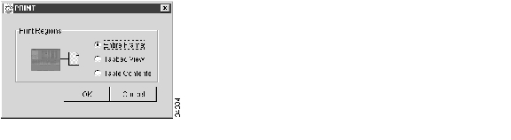
•
•
•
Figure 7-1 Selecting CTC data for print
Step 4
Step 5
Step 6
Step 7
DLP-139 Export CTC Data
Step 1
Step 2
Step 3
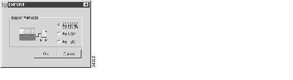
•
•
•
Figure 7-2 Selecting CTC data for export
Step 4
Step 5
•
•
•
Step 6
Step 7
Step 8
Note
Step 9
NTP-67 View Alarms, History, Events, and Conditions
Step 1
Step 2
Step 3
Step 4
Figure 7-3 Viewing alarms in the CTC network view
DLP-110 View Alarm History
Step 1
For the node-level alarm history, go to Step 2. For the network-level alarm message history, go to Step 3. For the card-level alarm message history, go to Step 5.
Step 2
a.
b.
Step 3
Step 4
Step 5
a.
b.
Note
Step 6
Step 7
Step 8
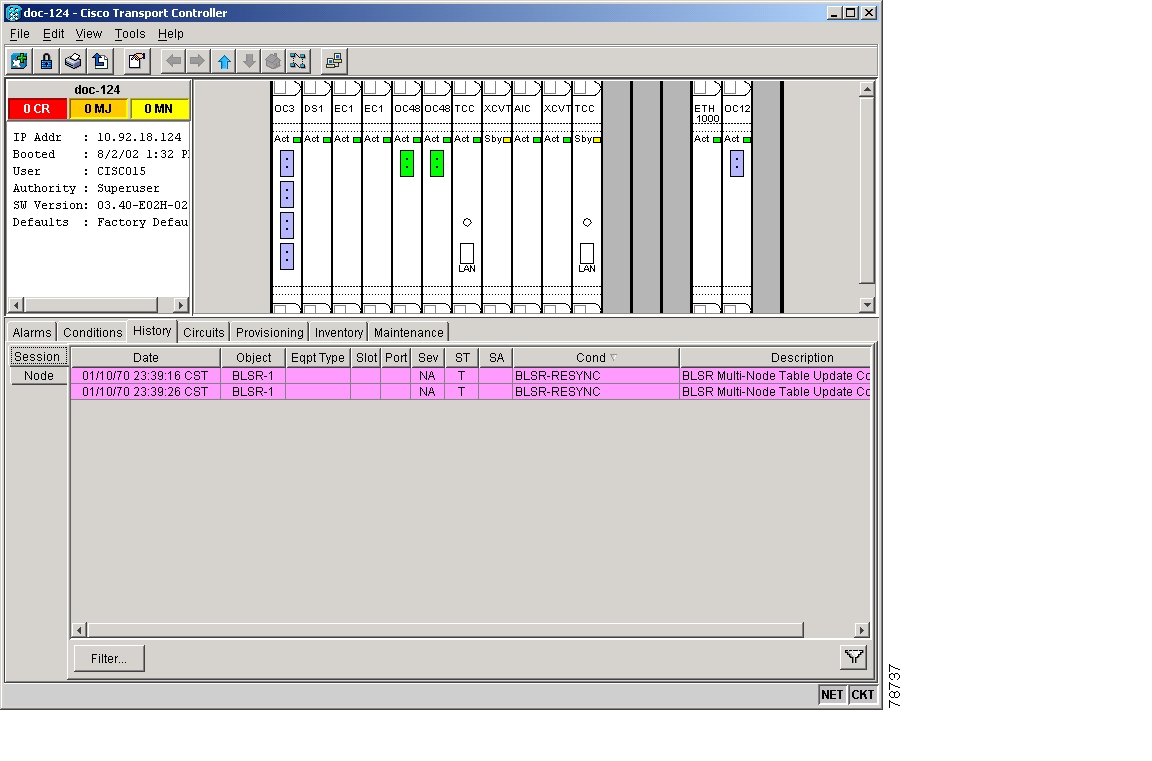
Tip
Figure 7-4 Viewing alarm history for the current session
Step 9
DLP-111 Changing the Maximum Number of Session Entries for Alarm History
Step 1
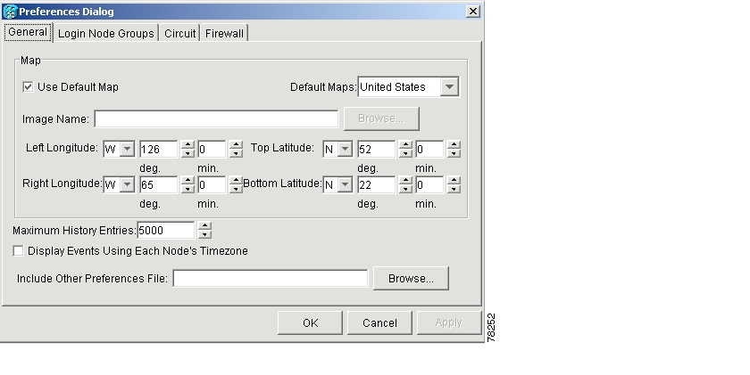
The CTC Preferences Dialog appears ( Figure 7-5).
Figure 7-5 CTC Preferences Dialog featuring Maximum History Entries
Step 2
Step 3
Note
Note
Step 4
DLP-112 Display Alarms and Events Using Each Node's Timezone
Step 1
The CTC Preferences Dialog appears ( Figure 7-6).
Figure 7-6 CTC Preferences Dialog featuring Maximum History Entries
Step 2
Step 3
Step 4
DLP-113 View Events and Synchronize Alarms
Step 1
Step 2
This button causes CTC to retrieve a current alarm summary for the node. This step is optional, since CTC updates the Alarms tab automatically as raise/clear messages arrive from the node.
Step 3
DLP-114 View Conditions
Step 1
Step 2
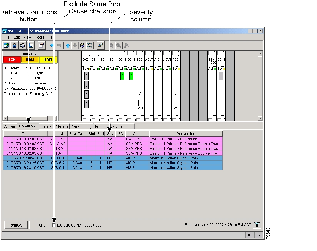
Conditions include all fault conditions raised on the node, whether or not they are reported (i.e. messages sent) to CTC and other clients. Conditions that are reported at Major, Minor, or Critical severities are alarms. Conditions that are reported at Not Alarmed are events. Conditions that are not reported at all are marked as Not Reported in the Conditions tab severity column.
Clicking Retrieve requests the current set of fault conditions from the node. The tab is not updated when things change on the node. The operator must click Retrieve to see any changes.
Conditions have a default severity of CR, MJ, MN, or NA but are not reported at this time due to exclusion or suppression (by CTC command or port or circuit state other than IS) are shown as NR on the Conditions tab. Conditions that are currently reported are shown at the chosen reporting severity.
Note
When ports are placed in OOS state, the Alarms Suppressed for Maintenance (AS-MT) condition is raised on them. For more information about placing the ONS 15454 in OOS state for performing loopback tests, or for information about alarm troubleshooting, refer to the Cisco ONS 15454 Troubleshooting Guide.Figure 7-7 Viewing fault conditions retrieved under the Conditions tabs
Step 3
According to Telcordia, exclusion rules apply to a query of "all conditions from a node" (the rules that apply in a "RTRV-ALM-ALL" TL1 command, but not in more specific TL1 RTRV-ALM commands). To match TL1 retrieval results, click the Exclude Same Root Cause checkbox on node view and network view, and leave it unchecked on card view.
Step 4
NTP-68 Delete Cleared Alarms from Display
Step 1
To delete node-level alarms, go to Step 2. To delete card-level alarms, go to Step 3. To delete network-level alarms, go to Step 4.
Step 2
a.
b.
This action will remove any cleared ONS 15454 alarms from the Alarms display. The rows of cleared alarms are colored white and have a C in their status (ST) column ( Figure 7-7).
Step 3
a.
b.
Step 5.Step 4
a.
b.
Step 5.Step 5
a.
b.
c.
NTP-69 View Alarm-Affected Circuits
Step 1
Step 2
Note
Note
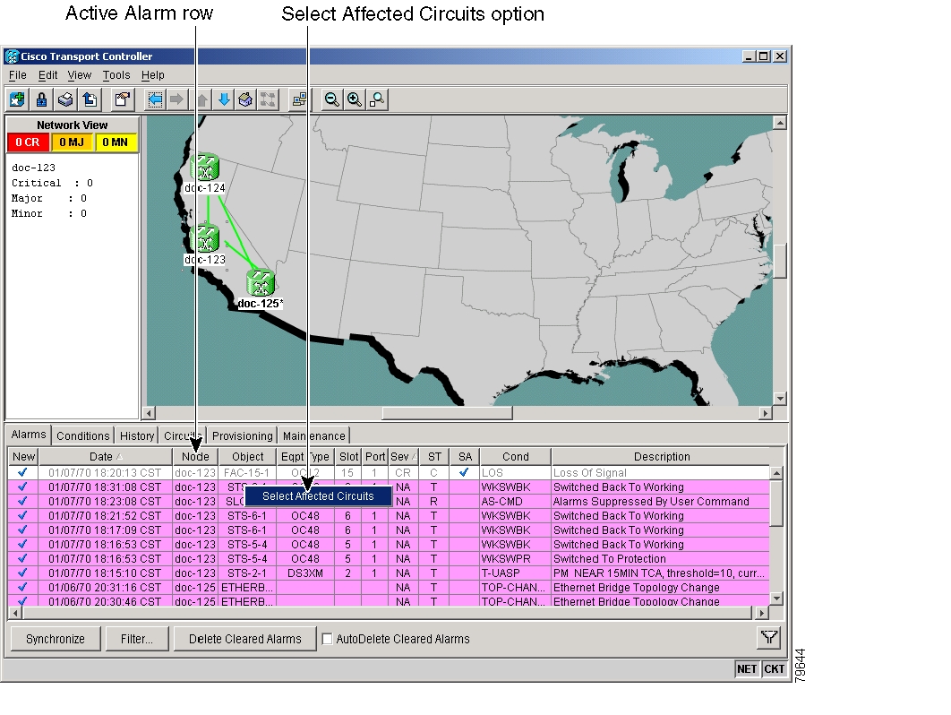
The Select Affected Circuit option appears on the shortcut menu ( Figure 7-8).
Figure 7-8 Selecting the Affected Circuits option
Step 3
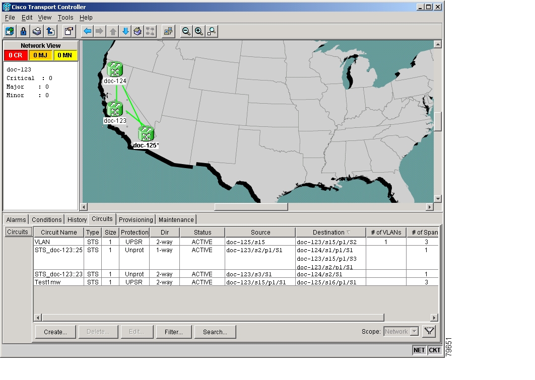
The Circuits pane appears with affected circuits highlighted ( Figure 7-9).
Figure 7-9 Highlighted circuit appears
Step 4
NTP-70 View Alarm Counts on the LCD for a Slot or Port
Step 1
Step 2
Step 3
Step 4
Figure 7-10 shows the LCD panel.
Figure 7-10 The LCD panel
Note
Note
NTP-71 Create, Download, and Assign Alarm Severity Profiles
Step 1
Step 2
Step 3
Step 4
DLP-115 Create Alarm Severity Profiles
Step 1
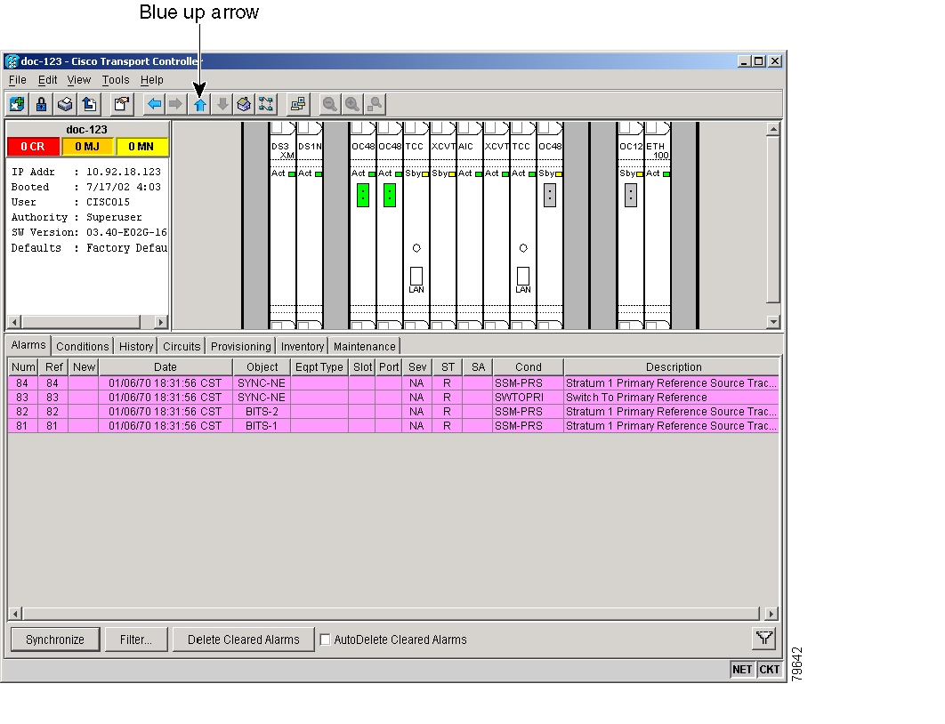
Figure 7-11 shows the blue up arrow tool on the node (default login) view.
Figure 7-11 Blue up arrow tool on node (default login) view
Step 2
Step 3
Step 4
Step 5
Step 6
Step 7
The Default alarm severity profile appears in the Alarm Profiles tab pane.
Step 8
Step 9
You can also clone any other profiles that appear under the Available button, except Inherited.
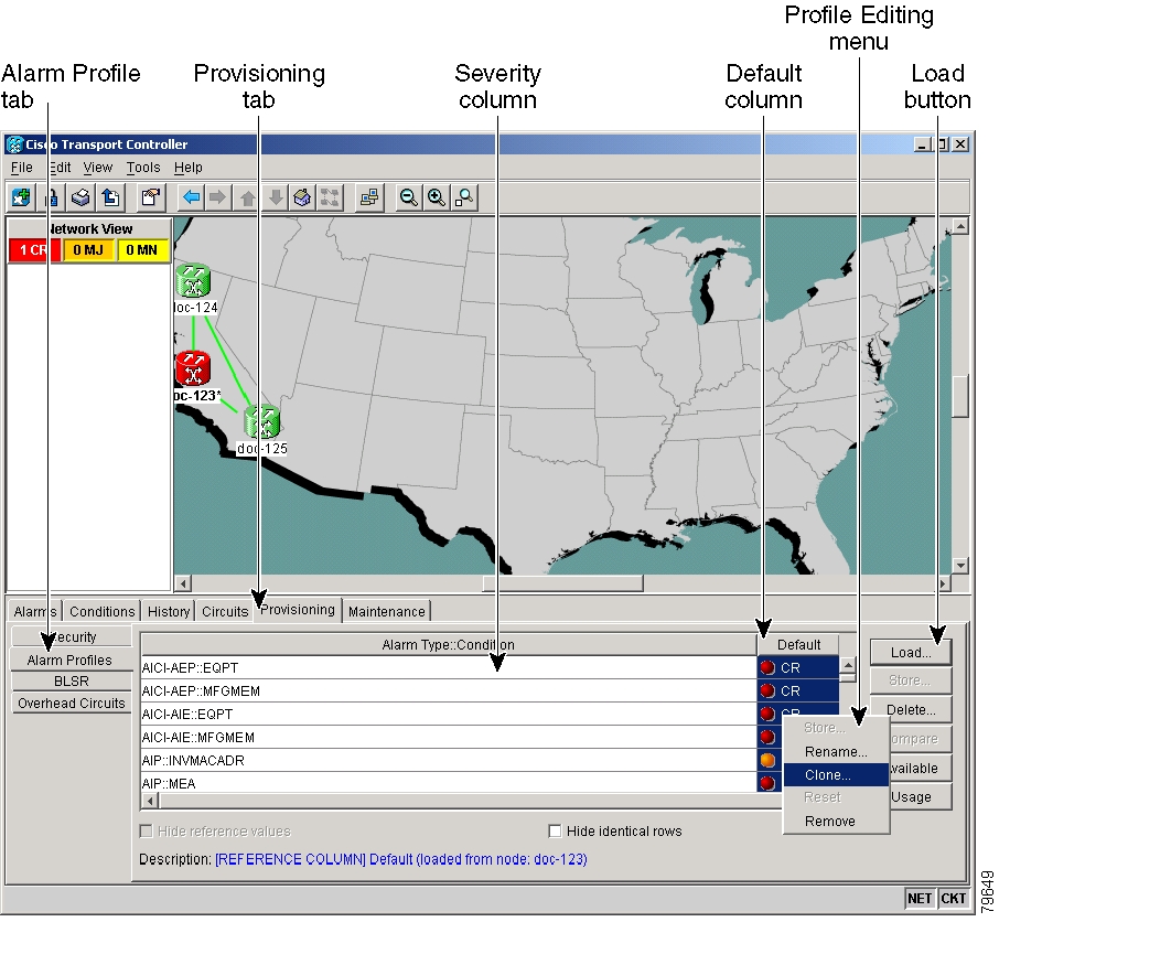
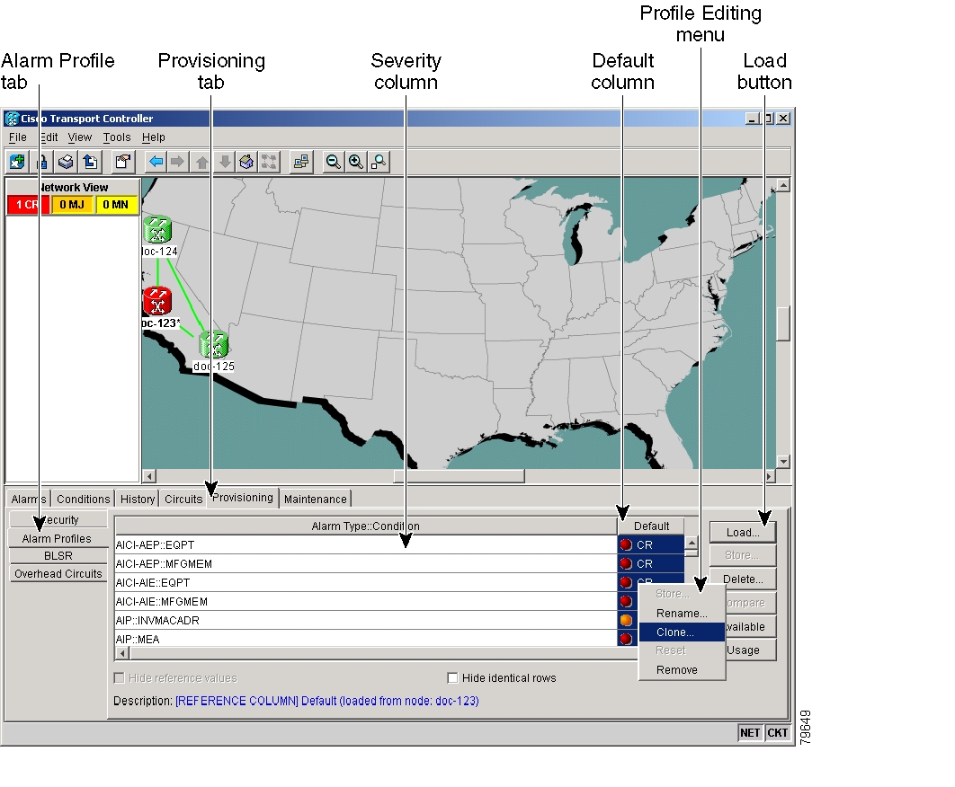
Figure 7-12 Alarm profiles window showing the default profiles of the listed alarms
Step 10
Profile names must be unique. If you try to import or name a profile that has the same name as another profile, CTC adds a suffix to create a new name. Long file names are supported.
Tip
Step 11
A new alarm profile (named in Step 10) is created. This profile duplicates the severities of the default profile and is added as a new column on the right side of the Alarm Profiles tab.
Step 12
a.
b.
c.
Step 13
Step 14
Step 15
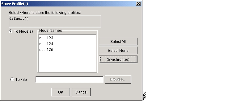
Figure 7-13 Store Profile(s) dialog window
Step 16
a.
–
–
–
Go to Step c.
b.
c.
Long file names are supported. CTC supplies a suffix of *.pfl.
d.
Step 17
Note
Note
DLP-223 Download an Alarm Severity Profile
Step 1
Figure 7-14 shows the blue up arrow tool on the node (default login) view.
Figure 7-14 Blue up arrow tool on node (default login) view
Step 2
Figure 7-15 Alarm window showing the default profiles of the listed alarms
Step 3
If you want to download a file from the local PC, a CD, or a network drive (if connected), go to Step 4. If you want to download a file from another connected node, go to Step 5.
Step 4
a.
The Open dialog box appears.
b.
c.
The file must have the *.pfl extension.
d.
e.
Step 5
a.
b.
Step 6
The downloaded profile appears on the right side of the Alarm Profiles tab.
Step 7
Step 8
Step 9
Figure 7-16 Store Profile(s) dialog window
Step 10
•
•
•
•
Step 11
DLP-116 Apply Alarm Profiles to Ports
Purpose
Use this task to apply a custom or default alarm severity profile to a port or ports.
Tools/Equipment
None
Prerequisite Procedures
DLP-115 Create Alarm Severity Profiles
Required/As Needed
As needed
Onsite/Remote
Onsite or remote
Security Level
Provisioning or higher
Step 1
Note
Note
Step 2
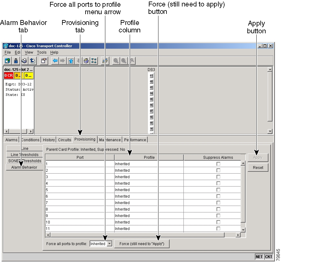
Figure 7-17 shows the profile of the affected DS-3 card. CTC shows Parent Card Profile: Inherited.
Go to Step 3 to apply profiles on a port-by-port basis. Go to Step 4 to apply profiles to all ports on a card.
Figure 7-17 Card view of a DS3 alarm profile
Step 3
a.
b.
c.
Step 4
a.
b.
c.
d.
Step 5
Tip
DLP-117 Apply Alarm Profiles to Cards and Nodes
Purpose
Use this task to apply a custom alarm profile to cards or nodes.
Tools/Equipment
None
Prerequisite Procedures
DLP-115 Create Alarm Severity Profiles
Required/As Needed
As needed
Onsite/Remote
Onsite or remote
Security Level
Provision
Step 1
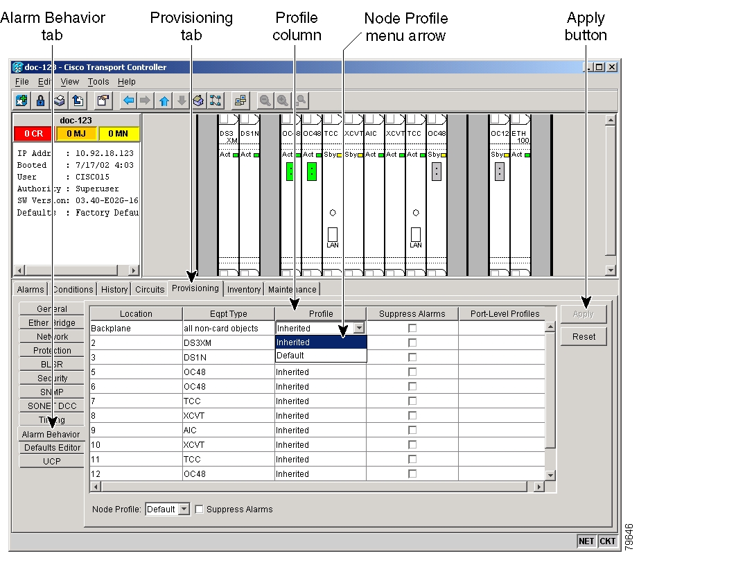
To apply profiles on a card basis, go to Step 2. To apply the profile to the entire node, go to Step 3.
Figure 7-18 Node (default login) view of a DS3 alarm profile
Step 2
a.
b.
c.
d.
Step 3
a.
b.
c.
d.
Step 4
Tip
DLP-118 Delete Alarm Severity Profiles
Step 1
Figure 7-19 shows the blue up arrow tool on the node (default login) view.
Figure 7-19 Blue up arrow tool on node (default login) view
Step 2
Step 3
Figure 7-20 shows the highlighted profile column.
Figure 7-20 Highlighted Alarm Profile column
Step 4
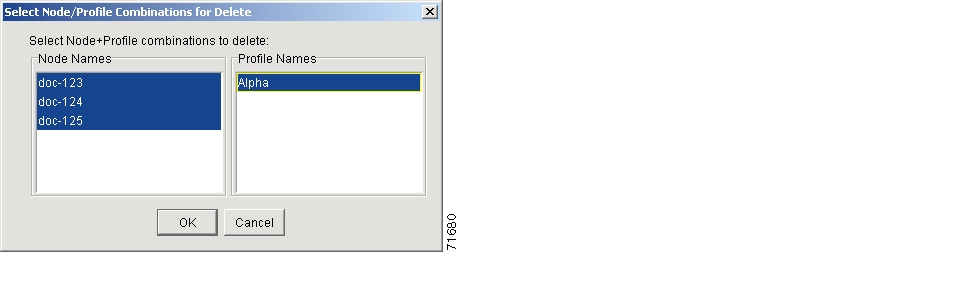
The Select Node/Profile Combination for Delete dialog window appears ( Figure 7-21).
Figure 7-21 Select Node/Profile Combination for Delete Window
Step 5
Step 6
Step 7
The Delete Alarm Profile confirmation dialog(s) appear.
Step 8
The profiles are now deleted from the nodes selected.
Step 9
Step 10
Note
Note
Note
NTP-168 Enable, Modify, or Disable Alarm Severity Filtering
Step 1
Step 2
Step 3
Step 4
DLP-225 Enable Alarm Filtering
Step 1
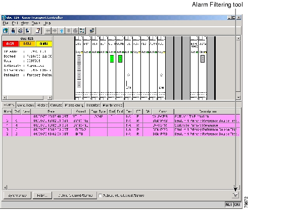
Figure 7-22 Node-level view of Alarms tab
.
Step 2
Alarm filtering is enabled if the tool is selected and disabled if the tool is not selected.
Alarm filtering will be enabled in the card, node, and network views of the Alarms tab at the node and for all other nodes in the network. If, for example, the Alarm Filter tool is enabled in the Alarms tab of the node view at one node, the Alarms tab in the network view and card view of that node will also show the tool enabled. All other nodes in the network will also have the tool enabled.
If you filter an alarm in card view, the alarm will still be displayed in node view. In this view, the card will display the color of the highest-level alarm. The alarm is also shown for the node in the network view.
Step 3
Step 4
Step 5
DLP-226 Modify Alarm and Condition Filtering Parameters
Step 1
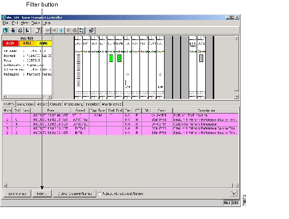
Figure 7-23 Node-level view of Alarms tab
.
Step 2
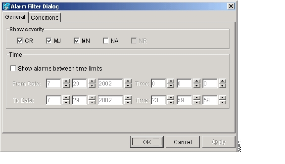
The Alarm Filter Dialog window appears, showing the General tab ( Figure 7-24).
Figure 7-24 Alarm Filter Dialog window, General tab
In the General tab Show Severity area, you can modify which alarm severities show through the alarm filter or the period of time to apply to the alarms. If you want to change the alarm severities shown in the filter, go to Step a. In the Time area, you can choose a time period that alarms are displayed for. If you want to change the time period that the alarms show for, go to Step b.
a.
When alarm filtering is disabled, all alarms show.
b.
Step 3
Step 4
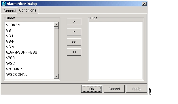
Figure 7-25 Alarm Filter Dialog window, Conditions tab
Conditions in the Show list are visible when alarm filtering is enabled. Conditions in the Hide list are invisible when alarm filtering is enabled. To move conditions individually from the Show list to the Hide list, click the > button. To move conditions individually from the Hide list to the Show list, click the
< button. To move conditions collectively from the Show list to the Hide list, click the >> button. To move conditions collectively from the Hide list to the Show list, click the << button.
Note
Step 5
Filter parameters for alarms and conditions are enforced when alarm filtering is enabled, and not enforced when alarm filtering is disabled.
Step 6
DLP-227 Disable Alarm Filtering
Step 1
Figure 7-26 Node-level view of Alarms tab
.
Step 2
Alarm filtering is enabled if the tool is selected, and disabled if the tool is not selected.
Step 3
Step 4
Step 5
NTP-72 Suppress and Unsuppress Alarm Reporting
Step 1
Step 2
Note
Step 3
DLP-119 Suppress Alarm Reporting
Step 1
At the card level, you can suppress alarms on a port-by-port basis. At the node level, you can suppress alarms on a card basis or on the entire node.
Step 2
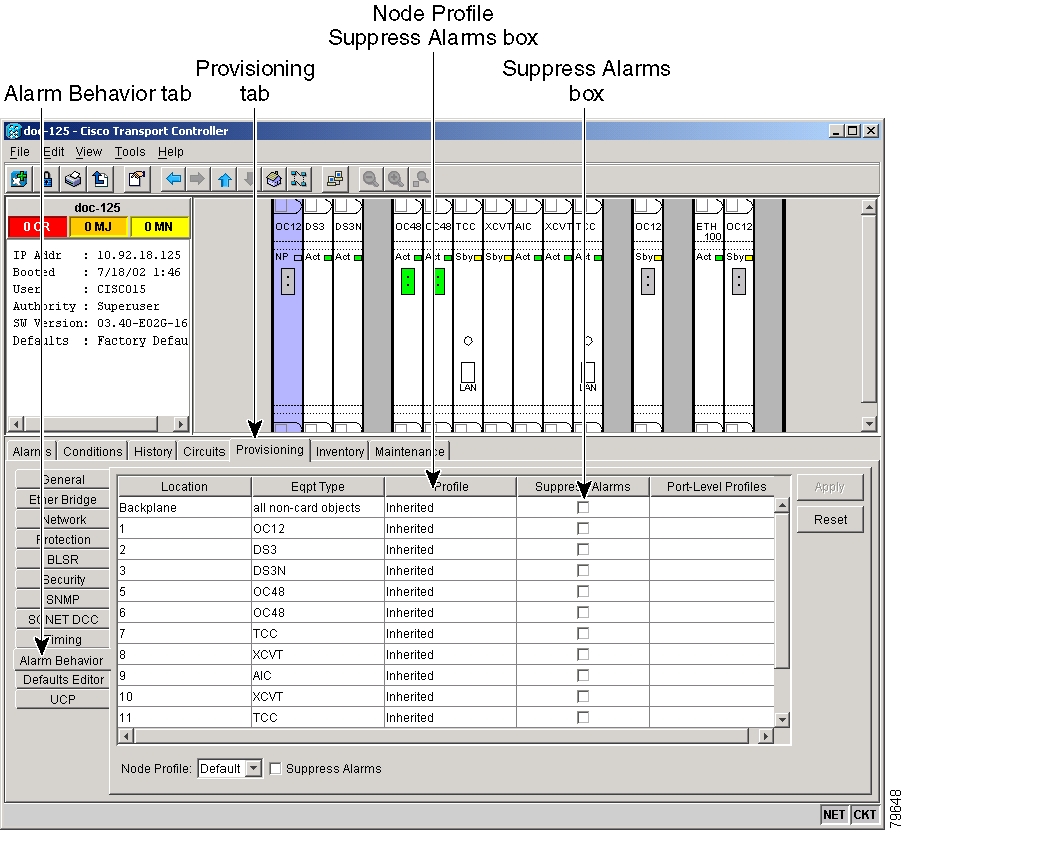
On the node (default login) view, row numbers correspond to slot numbers.
Figure 7-27 The Suppress Alarms checkbox
Step 3
The node sends out autonomous messages to clear any raised alarms.
Step 4
Caution
DLP-120 Unsuppress Alarm Reporting
Purpose
Use this task to discontinue alarm suppression and reenable alarm reporting on a port, card, or node.
Tools/Equipment
None
Prerequisite Procedures
DLP-119 Suppress Alarm Reporting
Required/As Needed
As needed
Onsite/Remote
Onsite or remote
Security Level
Provisioning
Step 1
Step 2
Step 3
Step 4
![]()
![]()
![]()
![]()
![]()
![]()
![]()
![]()
Posted: Fri Feb 22 14:19:56 PST 2008
All contents are Copyright © 1992--2008 Cisco Systems, Inc. All rights reserved.
Important Notices and Privacy Statement.