|
|

Table Of Contents
NTP-150 Locate and View Circuits
DLP-228 Filter the Display of Circuits
DLP-229 View Circuits on a Span
NTP-151 Modify Circuit Characteristics
DLP-230 Change a Circuit State
DLP-232 Change Active and Standby Span Color
DLP-233 Edit UPSR Circuit Path Selectors
NTP-78 Create a Monitor Circuit
DLP-136 Provision Path Trace on Circuit Source and Destination Ports
DLP-137 Provision Path Trace on OC-N Ports
Manage Circuits
This chapter explains how to manage Cisco ONS 15454 electrical, optical and Ethernet circuits.
Before You Begin
To create circuits, see "Create Circuits and VT Tunnels."
To clear any alarm or trouble conditions, refer to the Cisco ONS 15454 Troubleshooting Guide.
This section lists the chapter procedures (NTPs). Turn to a procedure for applicable tasks (DLPs).
1.
NTP-150 Locate and View Circuits—Complete as needed.
2.
3.
4.
5.
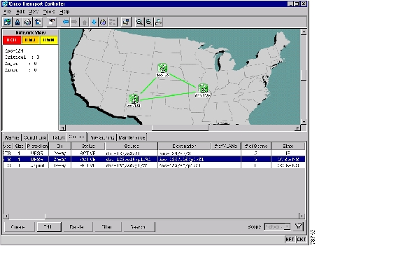
The ONS 15454 Circuits window ( Figure 9-1) displays information about circuits to help you manage the circuits. Two key attributes are status and state. Circuit status shown in Table 9-1, is CTC-generated information telling you what CTC has learned about the circuit. State, shown in Table 9-2, is a user-assigned, administrative status that defines whether the circuit is in or out of service. To carry circuit traffic, circuits must have a status of Active and a state of In Service (IS).
Figure 9-1 ONS 15454 Circuit window in network view
NTP-150 Locate and View Circuits
Purpose
This procedure provides tasks that you can use to locate and view ONS 15454 circuits.
Tools/Equipment
None
Prerequisite Procedures
Circuit creation procedure(s) in "Create Circuits and VT Tunnels"
Required/As Needed
As needed
Onsite/Remote
Onsite or remote
Security Level
Retrieve or higher
Step 1
Step 2
Step 3
Step 4
DLP-228 Filter the Display of Circuits
Step 1
•
•
•
Step 2
Step 3
a.
b.
–
–
–
–
–
–
–
Step 4
Step 5
Step 6
DLP-131 Search for Circuits
Step 1
•
•
•
Step 2
Step 3
Step 4
Step 5
•
•
•
•
Step 6
Step 7
Step 8
DLP-229 View Circuits on a Span
Purpose
View circuits on an ONS 15454 span.
Tools/Equipment
None
Prerequisite Procedures
Circuits must be created on the span. See "Create Circuits and VT Tunnels"
Required/As Needed
As needed
Onsite/Remote
Onsite or remote
Security Level
Retrieve or higher
Step 1
Step 2
•
•
On the Circuits on Span dialog box, you can view the following information for circuits provisioned on the span:
•
•
•
•
•
Note
Step 3
NTP-151 Modify Circuit Characteristics
Purpose
This procedure provides tasks that you can use to edit or change the properties of ONS 15454 circuits.
Tools/Equipment
None
Prerequisite Procedures
Circuits must exist on the network. See "Create Circuits and VT Tunnels" for circuit creation procedures.
Required/As Needed
As needed
Onsite/Remote
Onsite or remote
Security Level
Provisioning or higher
Step 1
Step 2
Step 3
Step 4
DLP-230 Change a Circuit State
Purpose
Use this task to change the state of a circuit.
Tools/Equipment
None
Prerequisite Procedures
Required/As Needed
As needed
Onsite/Remote
Onsite or remote
Security Level
Provisioning or higher
Step 1
Step 2
Note
Step 3
Note
Step 4
•
•
•
•
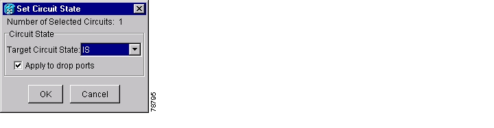
See Table 9-2 for additional information about circuit states.
Step 5
Figure 9-2 Changing circuit state
Step 6
Note
Step 7
DLP-231 Edit a Circuit Name
Purpose
Use this task to edit a circuit name.
Tools/Equipment
None
Prerequisite Procedures
Required/As Needed
As needed
Onsite/Remote
Onsite or remote
Security Level
Provisioning or higher
Step 1
Step 2
Step 3
Step 4
Step 5
Step 6
Step 7
DLP-232 Change Active and Standby Span Color
Step 1
Step 2
Step 3
•
•
•
Step 4
a.
b.
c.
Step 5
a.
b.
c.
Step 6
a.
b.
c.
d.
Step 7
DLP-233 Edit UPSR Circuit Path Selectors
Step 1
Step 2
Step 3
Note
Step 4
•
•
•
•
•
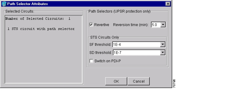
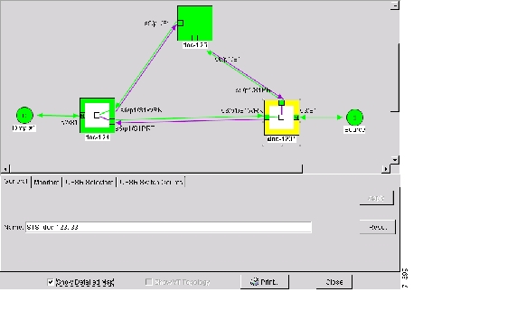
Step 5
Figure 9-3 Editing UPSR path selectors
Step 6
NTP-152 Delete Circuits
Purpose
Use this task to delete circuits.
Tools/Equipment
None
Prerequisite Procedures
Circuits must exist on the network. See "Create Circuits and VT Tunnels" for circuit creation procedures.
Required/As Needed
As needed
Onsite/Remote
Onsite or remote
Security Level
Provisioning or higher
Step 1
Step 2
Step 3
Step 4
Step 5
Step 6
Step 7
Step 8
NTP-78 Create a Monitor Circuit
Note
Note
Purpose
Use this task to create a monitor circuit that monitors traffic on primary, bidirectional circuits.
Tools/Equipment
None
Prerequisite Procedures
Bidirectional (2-way) circuits must exist on the network. See "Create Circuits and VT Tunnels" for circuit creation procedures.
Required/As Needed
As needed
Onsite/Remote
Onsite or remote
Security Level
Provisioning or higher
Step 1
Step 2
Step 3
Step 4
Step 5
Step 6
The Monitors tab displays ports that you can use to monitor the circuit selected in Step 4.
Note
Step 7
Note
Step 8
Step 9
Note
Step 10
Step 11
Step 12
Figure 9-4 shows a sample monitor circuit setup. VT1.5 traffic is received by Port 1 of the EC1-12 card at Node 1. To monitor the VT1.5 traffic, test equipment is plugged into Port 2 of the EC1-12 card and a monitor circuit to Port 2 is provisioned in CTC. (Circuit monitors are one-way.) This procedure assumes circuits have been created.
Figure 9-4 A VT1.5 monitor circuit received at an EC1-12 port
NTP-79 Create a J1 Path Trace
Purpose
Use this procedure to create a repeated, fixed-length string of characters used to monitor interruptions or changes to circuit traffic.
Tools/Equipment
ONS 15454 cards capable of transmitting and/or receiving path trace must be installed. See Table 9-3 for a list of cards.
Prerequisite Procedures
Path trace can only be provisioned on OC-N (STS) circuits. See "Create Circuits and VT Tunnels" for OC-N circuit creation procedures.
Required/As Needed
As needed
Onsite/Remote
Onsite or remote
Security Level
Provisioning or higher
Step 1
Step 2
•
•
DLP-136 Provision Path Trace on Circuit Source and Destination Ports
Purpose
Use this task to create a path trace on an STS circuit source and destination ports.
Tools/Equipment
ONS 15454 cards capable of transmitting and receiving path trace must be installed at the circuit source and destination ports. See Table 9-3 for a list of cards.
Prerequisite Procedures
Required/As Needed
As needed
Onsite/Remote
Onsite or remote
Security Level
Provisioning or higher
Note
Step 1
Step 2
If neither port is on a transmit/receive card, you will not be able to complete this procedure. If one port is on a transmit/receive card and the other on a receive-only card, you can set up the transmit string at the transmit/receive port and the receive string at the receive-only port, but you will not be able to transmit in both directions.
Step 3
Step 4
Step 5
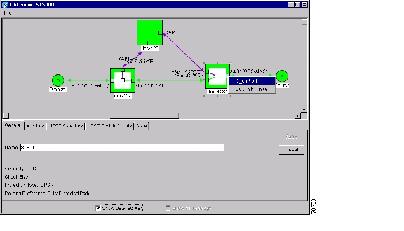
a.
Figure 9-5 Selecting the Edit Path Trace option
b.
c.
Step 6
a.
b.
c.
Step 7
a.
–
–
b.
c.
Note
d.
Step 8
a.
b.
–
–
c.
d.
e.
Step 9
•
•
•
Caution
The Expect and Receive strings are updated every few seconds as long as Path Trace Mode is set to Auto or Manual.
Step 10
When you display the detailed circuit window, path trace is indicated by an M (manual path trace) or an A (automatic path trace) at the circuit source and destination ports. Figure 9-7 shows an example.
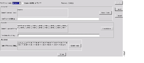
Figure 9-6 Setting up a path trace
Figure 9-7 Detailed circuit window with Manual expected string enabled
Step 11
DLP-137 Provision Path Trace on OC-N Ports
Purpose
Use this task to monitor a path trace on OC-N ports within the circuit path.
Tools/Equipment
ONS 15454 cards capable of receiving path trace must be installed at the OC-N circuit ports. See Table 9-3.
Prerequisite Procedures
DLP-136 Provision Path Trace on Circuit Source and Destination Ports.
Required/As Needed
As needed
Onsite/Remote
Onsite or remote
Security Level
Provisioning or higher
Step 1
Step 2
Step 3
Step 4
Step 5
Note
Step 6
•
•
Step 7
Step 8
Step 9
Step 10
![]()
![]()
![]()
![]()
![]()
![]()
![]()
![]()
Posted: Fri Feb 22 14:12:51 PST 2008
All contents are Copyright © 1992--2008 Cisco Systems, Inc. All rights reserved.
Important Notices and Privacy Statement.