|
|

Table Of Contents
NTP-24 Verify Card Installation
NTP-25 Set Up Name, Date, Time, and Contact Information
NTP-26 Set Up Network Information
DLP-63 Set Up Network Information Using CTC
DLP-64 Set the IP Address, Default Router, and Network Mask Using the LCD
DLP-66 Set Up or Change Open Shortest Path First Protocol
NTP-27 Set Up the ONS 15454 for Firewall Access
DLP-67 Provision the IIOP Listener Port on the ONS 15454
DLP-68 Provision the IIOP Listener Port on the CTC Computer
DLP-69 Set Up External or Line Timing
NTP-29 Create Protection Groups
DLP-71 Create a 1:1 Protection Group
DLP-72 Create a 1:N Protection Group
DLP-73 Create a 1+1 Protection Group
NTP-30 Create Users and Assign Security
DLP-74 Create a New User - Single Node
DLP-75 Create a New User - Multiple Nodes
NTP-31 Provision Line Status and Thresholds
DLP-76 Provision Line and Threshold Settings for the DS-1 Card
DLP-77 Provision Line and Threshold Settings for the DS-3 Card
DLP-78 Provision Line and Thresholds Settings for the DS3E Card
DLP-79 Provision Line Status and Thresholds for the DS3XM-6 Card
DLP-80 Provision Line Status and Thresholds for the EC1-12 Card
DLP-81 Provision OC-N Line Status and Thresholds
NTP-32 Provision the Alarm Interface Controller
DLP-82 Provision External Alarms and Controls
DLP-83 Provision the AIC Orderwire
DLP-84 Create an Orderwire Tunnel
NTP-34 Create Ethernet RMON Alarm Thresholds
Turn Up Shelf
This chapter explains how to provision a single Cisco ONS 15454 node and turn it up for service.
Before You Begin
Complete the procedures applicable to your site plan from the following chapters:
•
Chapter 1, "Install the Shelf and Backplane Cable"
•
•
This section lists the chapter procedures (NTPs). Turn to a procedure for applicable tasks (DLPs).
1.
2.
3.
4.
5.
6.
7.
8.
9.
10.
NTP-24 Verify Card Installation
Purpose
This procedure verifies that the ONS 15454 node is ready for turn up.
Tools/Equipment
An engineering work order, site plan, or other document specifying the ONS 15454 card installation.
Prerequisite Procedures
Chapter 1, "Install the Shelf and Backplane Cable"
Required/As Needed
Required
Onsite/Remote
Onsite
Step 1
Step 2
Note
Step 3
Note
Step 4
Note
Step 5
Step 6
Note
Step 7
Step 8
Step 9
Note
Step 10
Step 11
Step 12
Step 13
•
•
Step 14
NTP-25 Set Up Name, Date, Time, and Contact Information
Step 1
Step 2
Step 3
•
•
•
•
•
CTC uses the latitude and longitude to position ONS 15454 icons on the network view map. To convert a coordinate in degrees to degrees and minutes, multiply the number after the decimal by 60. For example, the latitude 38.250739 converts to 38 degrees, 15 minutes (.250739 x 60 = 15.0443, rounded to the nearest whole number).
Tip
•
If you do not use an SNTP or NTP server, complete the Date and Time fields. The ONS 15454 will use these fields for alarm dates and times. (CTC displays all alarms in the login node's time zone for cross network consistency.)
Note
If you check Use NTP/SNTP Server, type the IP address of either a) an NTP/SNTP server, or b) the IP address of an ONS 15454 with NTP/SNTP Server enabled. If you enable Enable Firewall for the ONS 15454 proxy server, external ONS 15454 NEs must reference the gateway ONS 15454 NE for NTP/SNTP timing.
Caution
•
•
•
Step 4
Step 5
Step 6
NTP-26 Set Up Network Information
Step 1
Step 2
Tip
Step 3
Step 4
Step 5
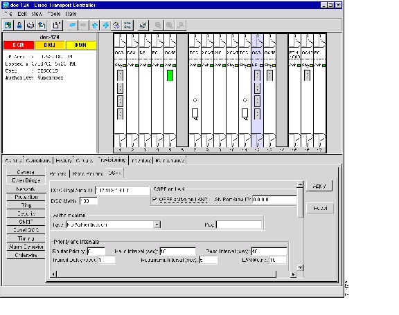
DLP-63 Set Up Network Information Using CTC
Purpose
This task provisions network access information for an ONS 15454 node.
Tools/Equipment
None
Prerequisite Procedures
NTP-24 Verify Card Installation
Required/As Needed
Required
Onsite/Remote
Onsite or remote
Caution
Step 1
Step 2
•
•
•
•
•
•
Note
•
"NTP-27 Set Up the ONS 15454 for Firewall Access" procedure to provision firewall access.•
–
–
–
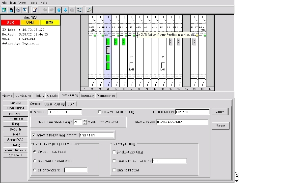
Figure 4-1 Setting up general network information
Step 3
Step 4
Both ONS 15454 TCC+ cards will reboot, one at a time. During this time (approximately 7-10 minutes), the active and standby TCC+ LEDs will go through the cycle shown in Table 4-1. Eventually, a "Lost node connection, switching to network view" message is displayed.
Step 5
Step 6
DLP-64 Set the IP Address, Default Router, and Network Mask Using the LCD
Note
Step 1
Step 2
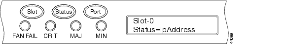
•
•
•
Figure 4-2 Selecting the IP address option
Step 3
Figure 4-3 Changing the IP address
Step 4
Tip
Step 5
Step 6
Step 7
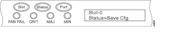
Figure 4-4 Selecting the Save Configuration option
Step 8
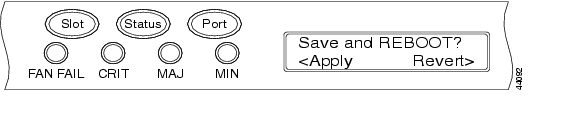
A Save and REBOOT message appears ( Figure 4-5).
Figure 4-5 Saving and rebooting the TCC+
Step 9
Saving the new configuration causes the TCC+ cards to reboot. During the reboot, a "Saving Changes - TCC Reset" message displays on the LCD. The LCD returns to the normal alternating display after the TCC+ reboot is complete (see Table 4-1 for reboot behavior).
Step 10
DLP-65 Create a Static Route
Purpose
Use this task to create a static route on the ONS 15454.
Tools/Equipment
None
Prerequisite Procedures
NTP-24 Verify Card Installation
Required/As Needed
Required if either of the following is true:
•
•
Onsite/Remote
Onsite or remote
Step 1
Step 2
Step 3
Step 4
•
•
•
•
Step 5
Note
Step 6
DLP-66 Set Up or Change Open Shortest Path First Protocol
Purpose
Use this task to enable the Open Shortest Path First (OSPF) routing protocol on the ONS 15454. Perform this task if you want to include the ONS 15454 in OSPF-enabled networks.
Tools/Equipment
None
Prerequisite Procedures
NTP-24 Verify Card Installation
You wll need the OSPF Area ID, Hello and Dead intervals, and authentication key (if OSPF authentication is enabled) provisioned on the router that the ONS 15454 is connected to.
Required/As Needed
As needed
Onsite/Remote
Onsite or remote
Step 1
Step 2
Figure 4-6 Enabling OSPF on the ONS 15454
Step 3
•
•
Step 4
•
•
Step 5
•
•
Step 6
The OSPF priority and intervals default to values most commonly used by OSPF routers. In the Priority and Intervals area, verify that these values match those used by the OSPF router where the ONS 15454 is connected.
•
•
•
•
•
•
Step 7
Note
a.
b.
–
–
–
–
c.
Step 8
a.
b.
Neighbor—The router ID of the Area 0 router.
Transit Delay (sec)—The service speed. One second is the default.
Hello Int (sec)—The number of seconds between OSPF "hello" packet advertisements sent by OSPF routers. Ten seconds is the default.
Auth Type—If the router where the ONS 15454 is connected uses authentication, choose Simple Password. Otherwise, choose No Authentication.
Retransmit Int (sec)—Sets the time that will elapse before a packet is resent. Five seconds is the default.
Dead Int (sec)—Sets the number of seconds that will pass while an OSPF router's packets are not visible before its neighbors declare the router down. Forty seconds is the default.
c.
Step 9
If you changed the Area ID, the TCC+ cards will reset, one at a time. The reset will take approximately 10-15 minutes. Table 4-1 shows the LED behavior during the TCC+ reset.
Step 10
NTP-27 Set Up the ONS 15454 for Firewall Access
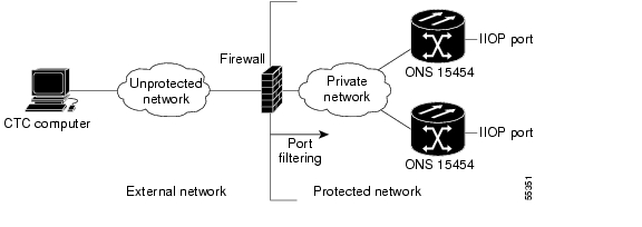
If an ONS 15454 or CTC computer resides behind a firewall that uses port filtering, you must enable an Internet Inter-ORB Protocol (IIOP) port on the ONS 15454 and/or CTC computer, depending on whether one or both devices reside behind a firewall.
Figure 4-7 shows ONS 15454s in a protected network and the CTC computer in an external network. In order for the computer to access the ONS 15454s, you provision the IIOP listener port specified by your firewall administrator on the ONS 15454. The ONS 15454 sends the port number to the CTC computer during the initial contact between the devices using Hyper-Text Transfer Protocol (HTTP). After the CTC computer obtains the ONS 15454 IIOP port, the computer opens a direct session with the node using the specified IIOP port.
Figure 4-7 ONS 15454s residing behind a firewall
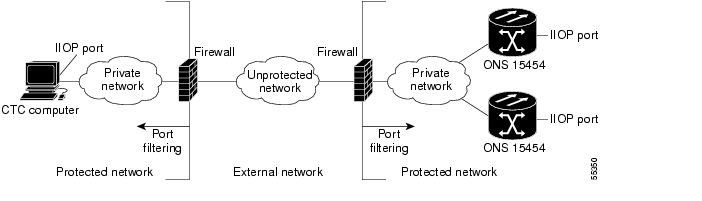
Figure 4-8 shows a CTC computer and ONS 15454 behind firewalls. In order for the computer to access the ONS 15454, you provision the IIOP port on the CTC computer and on the ONS 15454. Each firewall can use a different IIOP port. For example, if the CTC computer firewall uses IIOP port 4000, and the ONS 15454 firewall uses IIOP port 5000, 4000 is the IIOP port set on the CTC computer and 5000 is the IIOP port set on the ONS 15454.
Figure 4-8 A CTC computer and ONS 15454s residing behind firewalls
Step 1
Step 2
Step 3
Step 4
DLP-67 Provision the IIOP Listener Port on the ONS 15454
Purpose
Use this task to sets the IIOP listener port on the ONS 15454, which enables you to access ONS 15454s that reside behind a firewall.
Tools/Equipment
IIOP listener port number from LAN or firewall administrator
Prerequisite Procedures
NTP-24 Verify Card Installation
Required/As Needed
As needed
Onsite/Remote
Onsite or remote
Step 1
Step 2
•
•
•
Step 3
Step 4
Both ONS 15454 TCC+s will reboot, one at a time. The reboot will take approximately 15 minutes.
Step 5
DLP-68 Provision the IIOP Listener Port on the CTC Computer
Purpose
Use this task to select the IIOP listener port on CTC.
Tools/Equipment
IIOP listener port number from LAN or firewall administrator
Prerequisite Procedures
NTP-24 Verify Card Installation
Required/As Needed
Required only if the computer running CTC resides behind a firewall
Onsite/Remote
Onsite or remote
Step 1
Step 2
Step 3
•
•
•
Step 4
Step 5
Step 6
Step 7
Step 8
Step 9
NTP-28 Set Up Timing
Purpose
Use this procedure to provision the ONS 15454 timing.
Tools/Equipment
None
Prerequisite Procedures
Required/As Needed
Required
Onsite/Remote
Onsite or remote
Step 1
Step 2
Step 3
Note
Step 4
DLP-69 Set Up External or Line Timing
Purpose
Use this task to define the SONET timing source (external or line) for the ONS 15454.
Tools/Equipment
None
Prerequisite Procedures
NTP-24 Verify Card Installation
Required/As Needed
Required
Onsite/Remote
Onsite or remote
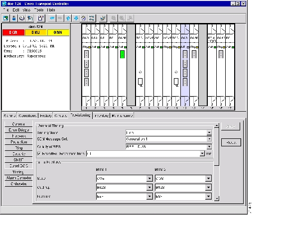
Step 1
Figure 4-9 Setting Up ONS 15454 timing
Step 2
•
•
•
•
•
Step 3
Note
•
•
•
•
•
•
Note
Step 4
Note
•
–
–
–
•
Step 5
Note
Step 6
DLP-70 Set Up Internal Timing
Purpose
Use this task to set up internal timing (Stratum 3) for an ONS 15454.
Tools/Equipment
None
Prerequisite Procedures
NTP-24 Verify Card Installation
Required/As Needed
As needed (use only if a BITS source is not available)
Onsite/Remote
Onsite or remote
Caution
Step 1
Step 2
•
•
•
•
•
Step 3
•
•
•
•
•
•
Step 4
•
–
–
–
•
Step 5
Step 6
Step 7
Step 8
•
Reference Lists
•
–
–
–
Step 9
Step 10
Step 11
NTP-29 Create Protection Groups
Step 1
Step 2
•
•
•
Note
Step 3
DLP-71 Create a 1:1 Protection Group
Purpose
Use this task to create a 1:1 electrical card protection group.
Tools/Equipment
Redundant DS-1, DS-3, EC-1 or DS3XM-6 cards should be installed in the shelf, or the ONS 15454 slots must be provisioned for two of these cards.
Prerequisite Procedures
NTP-24 Verify Card Installation
Required/As Needed
As needed
Onsite/Remote
Onsite or remote
Step 1
Step 2
Step 3
Step 4
•
•
•
After you choose the protect card, a list of cards available for protection is displayed under Available Cards, as shown in Figure 4-10. If no cards are available, no cards are displayed. If this occurs, you can not complete this task until you install the physical cards or provision the ONS 15454 slots.
Figure 4-10 Creating a 1:1 protection group
Step 5
Step 6
•
•
•
Step 7
Step 8
DLP-72 Create a 1:N Protection Group
Purpose
This task creates a DS-1 or DS-3 1:N protection group.
Tools/Equipment
A DS1N-14, DS3N-12, DS3N-12E must be installed in Slot 3 or Slot 15, and DS1-14, DS3-12, or DS3-12E cards must be installed on either side of the DS1N-1, DS3N-12, or DS3N-12E card, respectively.
Prerequisite Procedures
NTP-24 Verify Card Installation
Required/As Needed
As needed
Onsite/Remote
Onsite or remote
Step 1
Step 2
Step 3
Step 4
•
•
•
After you choose the protect card, a list of cards available for protection is displayed under Available Cards, as shown in Figure 4-10. If no cards are available, no cards are displayed. If this occurs, you will not be able to complete this task until you install the physical cards or provision the ONS 15454 slots.
Figure 4-11 Creating a 1:N protection group
Step 5
Step 6
•
•
•
Step 7
Step 8
DLP-73 Create a 1+1 Protection Group
Purpose
Use this task to create a 1+1 protection group for any OC-N card/port (OC-3, OC-12, OC-12-4, OC-48, OC-48AS, and OC-192).
Tools/Equipment
Installed OC-N cards or pre-provisioned slots
Prerequisite Procedures
NTP-24 Verify Card Installation
Required/As Needed
As needed
Onsite/Remote
Onsite or remote
Step 1
Step 2
Step 3
Step 4
•
•
•
•
Figure 4-12 Creating a 1+1 protection group
Step 5
Step 6
•
•
•
Step 7
Step 8
NTP-30 Create Users and Assign Security
Purpose
Use this procedure to create ONS 15454 users and assigns their security levels.
Tools/Equipment
None
Prerequisite Procedures
Required/As Needed
As needed
Onsite/Remote
Onsite or remote
Step 1
Note
Step 2
Note
Step 3
DLP-74 Create a New User - Single Node
Purpose
Use this task to create a new user for one ONS 15454.
Tools/Equipment
None
Prerequisite Procedures
NTP-24 Verify Card Installation
Required/As Needed
Required to add users to a node, although users can be added using TL1.
Onsite/Remote
Onsite or remote
Step 1
Step 2
Step 3
•
•
•
•
Note
Step 4
Step 5
DLP-75 Create a New User - Multiple Nodes
Purpose
Add a new user to multiple ONS 15454s.
Tools/Equipment
None
Prerequisite Procedures
NTP-24 Verify Card Installation
Required/As Needed
As needed
Onsite/Remote
Onsite or remote
Note
Step 6
Step 7
Step 8
Step 9
•
•
•
•
Note
Step 10
Step 11
Step 12
Step 13
NTP-31 Provision Line Status and Thresholds
Note
Step 1
Step 2
Step 3
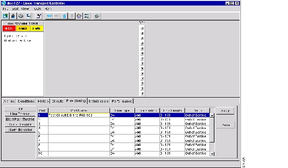
Figure 4-13 Provisioning line parameters on the DS1-14 card
Step 4
•
•
•
•
•
•
Step 5
DLP-76 Provision Line and Threshold Settings for the DS-1 Card
Purpose
Provisions the line status and thresholds for the DS-1 card
Tools/Equipment
None
Prerequisite Procedures
NTP-24 Verify Card Installation
Required/As Needed
As needed
Onsite/Remote
Onsite or remote
Step 1
Table 4-4 Line Options for DS1-14 and DS1N-14 Cards
Port #
Port number
1 - 14 (read-only)
Port
Port name
User-defined, up to 32 alphanumeric/ special characters. Blank by default
To enter a name for the port, click the cell and type the name. To change a name, double-click the cell, then edit the text.
Line Type
Defines the line framing type
•
•
•
Line Coding
Defines the DS-1 transmission coding type
•
•
Line Length
Defines the distance (in feet) from backplane connection to the next termination point
•
•
•
•
•
Status
Places port in or out of service
See the "DLP-86 Put Ports In or Out of Service" task on page 5-4
Step 2
Step 3
Step 4
Step 5
Step 6
Step 7
Step 8
Step 9
Step 10
Step 11
Note
Step 12
DLP-77 Provision Line and Threshold Settings for the DS-3 Card
Purpose
Use this task to provision transmission settings (line status and thresholds) for the DS3-12 and DS3N-12 cards.
Tools/Equipment
None
Prerequisite Procedures
NTP-24 Verify Card Installation
Required/As Needed
As needed
Onsite/Remote
Onsite or remote
Step 1
Note
Table 4-8 Line Options for DS3-12 or DS3N-12 Cards
Port #
Port number
1 - 12
Port
Port name
User-defined, up to 32 alphanumeric/ special characters. Blank by default
To enter a name for the port, click the cell and type the name. To change a name, double-click the cell, then edit the text.
Line Length
Defines the distance (in feet) from backplane connection to the next termination point
•
•
Status
Places port in or out of service
See the "DLP-86 Put Ports In or Out of Service" task on page 5-4
Step 2
Step 3
Step 4
Step 5
Step 6
Step 7
Step 8
Note
Step 9
DLP-78 Provision Line and Thresholds Settings for the DS3E Card
Note
Purpose
Use this task to provision transmission settings (line status and thresholds) for the DS3-12E or DS3N-12E card.
Tools/Equipment
None
Prerequisite Procedures
NTP-24 Verify Card Installation
Required/As Needed
As needed
Onsite/Remote
Onsite or remote
Step 1
Table 4-11 Line Options for the DS3-12E and DS3N-12E Cards
Port #
Port number
1 - 12 (Read-only)
Port
Port name
User-defined, up to 32 alphanumeric/ special characters. Blank by default
To enter a name for the port, click the cell and type the name. To change a name, double-click the cell, then edit the text.
Line Type
Defines the line framing type
•
•
•
Detected Line Type
Displays the detected line type
Read-only
Line Coding
Defines the DS3E transmission coding type
•
Line Length
Defines the distance (in feet) from backplane connection to the next termination point
•
•
Status
Places port in or out of service
See the "DLP-86 Put Ports In or Out of Service" task on page 5-4
Step 2
Step 3
Step 4
Step 5
Step 6
Step 7
Step 8
Step 9
Step 10
Step 11
Note
Step 12
DLP-79 Provision Line Status and Thresholds for the DS3XM-6 Card
Purpose
Use this task to provision transmission settings (line status and thresholds) for the DS3XM-6 card.
Tools/Equipment
None
Prerequisite Procedures
NTP-24 Verify Card Installation
Required/As Needed
As needed
Onsite/Remote
Onsite or remote
Note
Step 1
Table 4-15 Line Options for the DS3XM-6 Parameters
Port #
Port number
1 - 6 (read-only)
Port
Port name
User-defined, up to 32 alphanumeric/ special characters. Blank by default
To enter a name for the port, click the cell and type the name. To change a name, double-click the cell, then edit the text.
Line Type
Defines the line framing type
•
•
Line Coding
Defines the DS-1 transmission coding type that is used
•
Line Length
Defines the distance (in feet) from backplane connection to the next termination point
•
•
Status
Places port in or out of service
See the "DLP-86 Put Ports In or Out of Service" task on page 5-4
Step 2
Step 3
Step 4
Step 5
Step 6
Step 7
Step 8
Step 9
Step 10
Step 11
Note
Step 12
DLP-80 Provision Line Status and Thresholds for the EC1-12 Card
Purpose
Use this task to provision transmission settings (line status and thresholds) for the EC1-12 card.
Tools/Equipment
None
Prerequisite Procedures
NTP-24 Verify Card Installation
Required/As Needed
Performed as needed
Onsite/Remote
Onsite or remote
Step 1
Note
Note
Table 4-19 Line options for the EC1-12 card
Port #
EC-1 card port #
1 - 12
Port Name
Name assigned to the port (optional)
User-defined, up to 32 alphanumeric/ special characters. Blank by default
To enter a name for the port, click the cell and type the name. To change a name, double-click the cell, then edit the text.
PJStsMon#
Sets the STS that will be used for pointer justification. If set to zero, no STS is used.
•
•
Line Length (feet)
Defines the distance (in feet) from backplane to next termination point
•
•
Rx Equalization
For early EC1-12 card versions, equalization can be turned off if the line length is short or the environment is extremely cold; Rx Equalization should normally be set to On
•
•
Status
Places the port in or out of service
See the "DLP-86 Put Ports In or Out of Service" task on page 5-4
Step 2
Step 3
Step 4
Step 5
Note
Note
Step 6
DLP-81 Provision OC-N Line Status and Thresholds
Purpose
Use this task to provision transmission settings (line status and thresholds) for ONS 15454 OC-3, OC-12, OC-48, and OC-192 cards.
Tools/Equipment
None
Prerequisite Procedures
NTP-24 Verify Card Installation
Required/As Needed
As needed
Onsite/Remote
Onsite or remote
Step 1
Step 2
Step 3
Step 4
Note
Step 5
Note
Note
Step 6
NTP-32 Provision the Alarm Interface Controller
Step 1
Step 2
Step 3
Tip
Step 4
DLP-82 Provision External Alarms and Controls
Purpose
Use this task to provisions external alarms and controls on the AIC card.
Tools/Equipment
An AIC card must be installed in Slot 9.
Prerequisite Procedures
NTP-24 Verify Card Installation
Required/As Needed
As needed
Onsite/Remote
Onsite or remote
Note
Step 1
a.
b.
Step 2
Step 3
Step 4
•
•
•
•
•
•
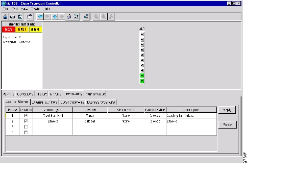
Figure 4-14 Provisioning external alarms on the AIC card
Step 5
Step 6
Step 7
•
•
•
•
Step 8
Step 9
Step 10
DLP-83 Provision the AIC Orderwire
Purpose
Use this task to provision orderwire on the AIC card.
Tools/Equipment
An AIC card must be installed in Slot 9.
Prerequisite Procedures
NTP-24 Verify Card Installation
Required/As Needed
As needed
Onsite/Remote
Onsite or remote
Step 1
Step 2
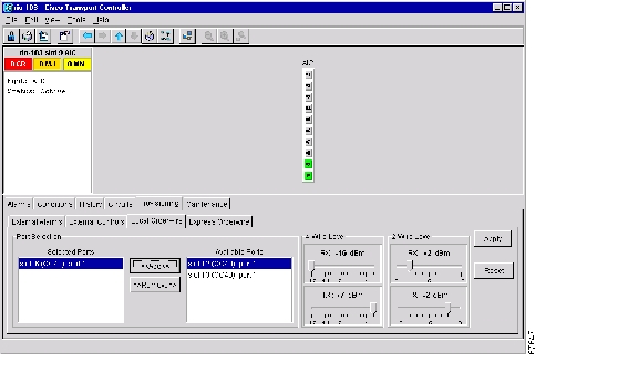
The Local Orderwire subtab is shown in Figure 4-15. Provisioning procedures are the same for both types of orderwire.
Caution
Figure 4-15 Provisioning local orderwire
Step 3
Step 4
Step 5
Step 6
DLP-84 Create an Orderwire Tunnel
Purpose
This task creates an tunnel to allow orderwire provisioned on ONS 15454s with AIC cards to be transported across ONS 15454s that do not have an AIC card installed.
Tools/Equipment
None
Prerequisite Procedures
NTP-24 Verify Card Installation
Required/As Needed
As needed
Onsite/Remote
Onsite or remote
Step 1
Step 2
Step 3
a.
b.
Step 4
Figure 4-16 Provisioning local orderwire
Step 5
NTP-33 Set Up SNMP
Purpose
Sets up SNMP for the ONS 15454.
Tools/Equipment
None
Prerequisite Procedures
Required/As Needed
Required if SNMP is used at your installation
Onsite/Remote
Onsite or remote
Step 1
Step 2
Step 3
Step 4
•
•
Note
•
•
•
Note
Figure 4-17 Setting SNMP
Step 5
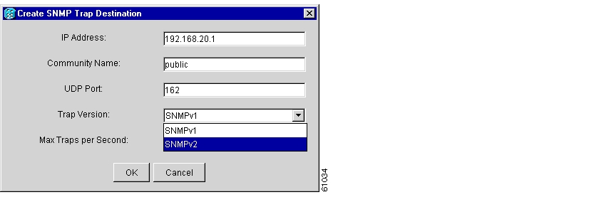
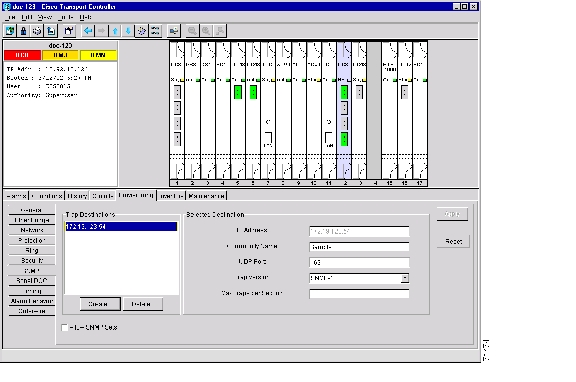
Step 6
Figure 4-18 SNMP Trap Destinations
Step 7
NTP-34 Create Ethernet RMON Alarm Thresholds
Step 1
Step 2
Step 3
The Create Ether Threshold dialog box ( Figure 4-19) opens.
Figure 4-19 Creating RMON thresholds
Step 4
Step 5
Step 6
Step 7
Step 8
Step 9
Step 10
Note
Step 11
A falling threshold is the counterpart to a rising threshold. When the number of occurrences is above the rising threshold and then drops below a falling threshold, it resets the rising threshold. For example, when the network problem that caused 1001 collisions in 15 minutes subsides and creates only 799 collisions in 15 minutes, occurrences fall below a falling threshold of 800 collisions. This resets the rising threshold so that if network collisions again spike over a 1000 per 15 minute period, an event again triggers when the rising threshold is crossed. An event is triggered only the first time a rising threshold is exceeded (otherwise a single network problem might cause a rising threshold to be exceeded multiple times and cause a flood of events).
Step 12
Step 13
![]()
![]()
![]()
![]()
![]()
![]()
![]()
![]()
Posted: Fri Feb 22 14:24:39 PST 2008
All contents are Copyright © 1992--2008 Cisco Systems, Inc. All rights reserved.
Important Notices and Privacy Statement.