|
|

Table Of Contents
NTP-67 View Alarms, History, Events, and Conditions
DLP-111 Changing the Maximum Number of Session Entries for Alarm History
DLP-112 Display Events Using Each Node's Timezone
DLP-113 View Events and Synchronize Alarms
NTP-69 View Alarm-Affected Circuits
NTP-70 View Alarm Counts on the LCD for a Slot or Port
NTP-71 Create and Assign Alarm Severity Profiles
DLP-115 Create Alarm Severity Profiles
DLP-116 Apply Alarm Profiles to Ports and Cards
DLP-117 Apply Alarm Profiles to Cards and Nodes
DLP-118 Delete Alarm Severity Profiles
NTP-72 Suppress and Raise Alarm Reporting
DLP-119 Suppress Alarm Reporting
Manage Alarms
This chapter explains how to view and manage the alarms and conditions on a Cisco ONS 15454.
Note
CTC detects and reports SONET alarms generated by the Cisco ONS 15454 and the larger SONET network. You can use CTC to monitor and manage alarms at a card, node, or network level and view alarm counts on the LCD front panel. Default alarm severities conform to the Telcordia GR-253 standard, but you can reset severities to customized alarm profiles or suppress CTC alarm reporting. For alarm troubleshooting information, refer to the Cisco ONS 15454 Troubleshooting Guide.
Before You Begin
Before performing any of the following procedures, investigate all alarms and clear any trouble conditions. Refer to the Cisco ONS 15454 Troubleshooting Guide as necessary.
This section lists the chapter procedures (NTPs). Turn to a procedure for applicable tasks (DLPs).
1.
2.
3.
4.
5.
6.
NTP-67 View Alarms, History, Events, and Conditions
Step 1
Step 2
Step 3
Step 4
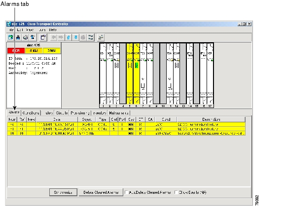
Figure 7-1 Viewing alarms in the CTC node view
Step 5
DLP-110 View Alarm History
Step 1
a.
b.
c.
Step 2
a.
b.
c.
Step 3
a.
Alarms and events that have occurred on the network since you logged into CTC are displayed.
b.
Step 4
a.
b.
c.
Note
Step 5
Step 6
Step 7
Tip
Figure 7-2 Viewing all alarms reported for the current session
Step 8
DLP-111 Changing the Maximum Number of Session Entries for Alarm History
Step 1
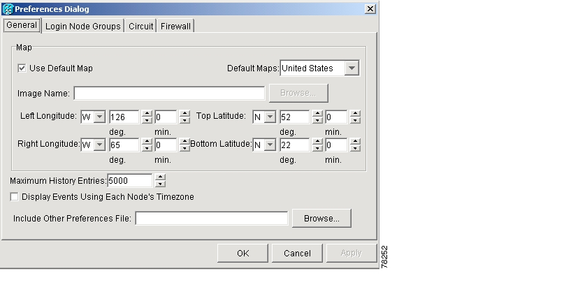
The CTC Preferences Dialog appears.
Figure 7-3 CTC Preferences Dialog featuring Maximum History Entries
Step 2
Step 3
Note
Note
Step 4
DLP-112 Display Events Using Each Node's Timezone
Step 1
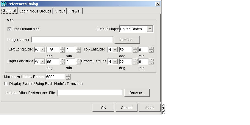
The CTC Preferences Dialog appears.
Figure 7-4 CTC Preferences Dialog featuring Maximum History Entries
Step 2
Step 3
Step 4
DLP-113 View Events and Synchronize Alarms
Step 1
Step 2
Step 3
Although CTC displays alarms and events in real time, the Synchronize button allows you to verify the alarm display. This is particularly useful during provisioning or troubleshooting.
Step 4
DLP-114 View Conditions
Purpose
Use this task to view conditions at the card, node, or network level.
Tools/Equipment
None
Prerequisite Procedures
Required/As Needed
As needed
Onsite/Remote
Onsite or remote
Step 1
Step 2
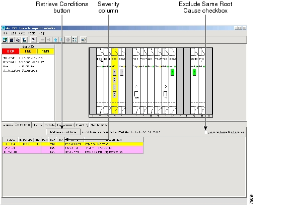
Events include both alarms and conditions. Alarms are conditions with a severity of minor (MN), major (MJ) or critical (CR). Conditions are events with a severity of not alarmed (NA) or not reported (NR).
Figure 7-5 Viewing fault conditions retrieved under the Conditions tabs
Step 3
According to Telcordia, exclusion rules apply to a query of "all conditions from a node" (the rules that apply in a "RTRV-ALM-ALL" TL1 command, but not in more specific TL1 RTRV-ALM commands). To match TL1 retrieval results, check this box on node view and network view and leave it unchecked on card view.
Step 4
NTP-68 Delete Alarms
Purpose
Use this procedure to delete ONS 15454 alarms that have been cleared.
Tools/Equipment
None
Prerequisite Procedures
None
Required/As Needed
As needed
Onsite/Remote
Onsite or remote
Step 1
Step 2
a.
b.
This action will remove any cleared ONS 15454 alarms from the Alarms display. The rows of cleared alarms are colored white and have a C in their status (ST) column ( Figure 7-5).
Step 3
a.
b.
Step 4
a.
b.
Step 5
NTP-69 View Alarm-Affected Circuits
Step 1
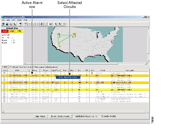
Step 2
Note
The Select Affected Circuit dialog appears ( Figure 7-6).
Figure 7-6 Selecting the Affected Circuits option
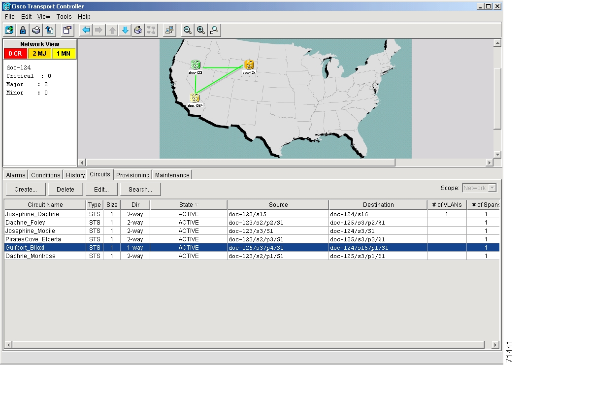
Step 3
The Circuits screen appears with affected circuits highlighted ( Figure 7-7).
Figure 7-7 Highlighted circuit appears
Step 4
NTP-70 View Alarm Counts on the LCD for a Slot or Port
Purpose
Use this procedure to view alarm counts using only the front panel LCD.
Tools/Equipment
None
Prerequisite Procedures
None
Required/As Needed
As needed
Onsite/Remote
Onsite or remote
Step 1
Step 2
Step 3
Step 4
Figure 7-8 shows the LCD panel.
Figure 7-8 The LCD panel
Note
Note
Step 5
NTP-71 Create and Assign Alarm Severity Profiles
Step 1
Step 2
Step 3
Note
Step 4
DLP-115 Create Alarm Severity Profiles
Purpose
Use this task to create severity profiles for alarms.
Tools/Equipment
None
Prerequisite Procedures
Required/As Needed
As needed
Onsite/Remote
Onsite or remote
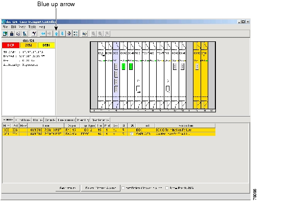
Step 1
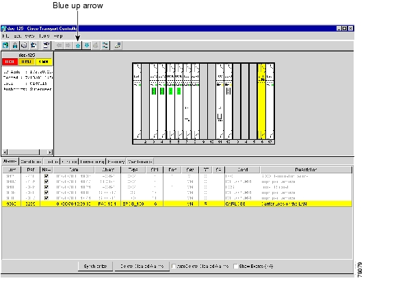
Figure 7-9 shows the blue up arrow tool on the node view
Figure 7-9 Blue up arrow tool on node view
Step 2
Step 3
Step 4
Step 5
Step 6
Step 7
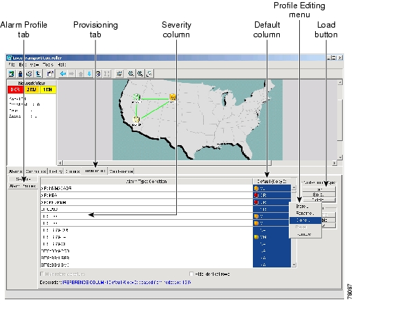
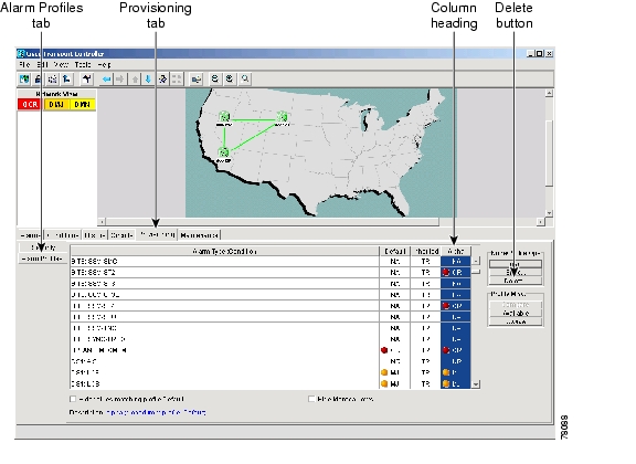
Figure 7-10 Alarm profiles screen showing the default profiles of the listed alarms
Step 8
Profile names must be unique. If you try to import or name a profile that has the same name as another profile, CTC adds a suffix to create a new name.
Step 9
A new alarm profile (named in Step 8) is created. This profile duplicates the severities of the default profile and is added as a new column on the far right-hand side.
Step 10
a.
b.
c.
d.
e.
f.
Step 11
Note
Note
Note
DLP-116 Apply Alarm Profiles to Ports and Cards
Purpose
Use this task to apply alarm severity profiles to a port or a card.
Tools/Equipment
None
Prerequisite Procedures
DLP-115 Create Alarm Severity Profiles
Required/As Needed
As needed
Onsite/Remote
Onsite or remote
Step 1
Note
Step 2
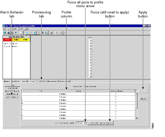
Figure 7-11 shows the affected DS-1 card; the CTC shows Parent Card Profile: Inherited.
Figure 7-11 Card view of a DS1 alarm profile
Step 3
a.
b.
c.
Step 4
a.
b.
c.
d.
Step 5
Tip
DLP-117 Apply Alarm Profiles to Cards and Nodes
Purpose
Use this task to assign alarm profiles to cards or nodes.
Tools/Equipment
None
Prerequisite Procedures
DLP-115 Create Alarm Severity Profiles
Required/As Needed
As needed
Onsite/Remote
Onsite or remote
Step 1
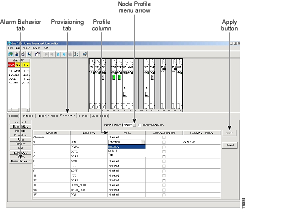
Figure 7-12 Node view of a DS1 alarm profile
Step 2
a.
b.
c.
Step 3
a.
b.
c.
Step 4
Tip
DLP-118 Delete Alarm Severity Profiles
Purpose
Use this task to delete severity profiles for alarms.
Tools/Equipment
None
Prerequisite Procedures
Required/As Needed
As needed
Onsite/Remote
Onsite or remote
Step 1
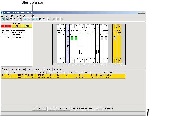
Figure 7-13 shows the blue up arrow tool on the node view.
Figure 7-13 Blue up arrow tool on node view
Step 2
Step 3
Figure 7-14 shows the highlighted profile column.
Figure 7-14 Highlighted Profile column
Step 4
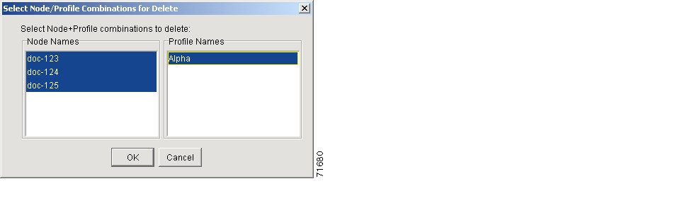
The Select Node/Profile Combination for Delete Window appears.
Figure 7-15 Select Node/Profile Combination for Delete Window
Step 5
Step 6
Step 7
Delete Alarm Profile confirmation dialog(s) appear.
Step 8
The profiled are now deleted from the nodes selected.
Step 9
Step 10
Note
Note
Note
NTP-72 Suppress and Raise Alarm Reporting
Step 1
Step 2
Note
Step 3
Step 4
DLP-119 Suppress Alarm Reporting
Step 1
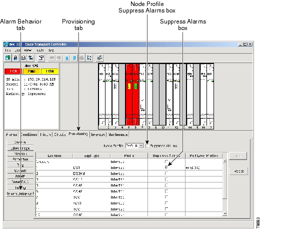
At the card level, you can suppress alarms on a port-by-port basis. At the node level, you can suppress alarms on a card-by-card basis or on the entire node.
Step 2
Figure 7-16 The suppress alarms checkbox
Step 3
The node sends out autonomous messages to clear any raised alarms.
Step 4
Caution
DLP-120 Raise Alarm Reporting
Purpose
Use this task to remove the alarm suppression command on a port, card, or node.
Tools/Equipment
None
Prerequisite Procedures
DLP-119 Suppress Alarm Reporting
Required/As Needed
As needed
Onsite/Remote
Onsite or remote
Step 1
Step 2
Step 3
Step 4
![]()
![]()
![]()
![]()
![]()
![]()
![]()
![]()
Posted: Fri Feb 22 13:09:18 PST 2008
All contents are Copyright © 1992--2008 Cisco Systems, Inc. All rights reserved.
Important Notices and Privacy Statement.