|
|

Table Of Contents
NTP-73 Enable Performance Monitoring
DLP-121 Enable Pointer Justification Count Performance Monitoring
DLP-122 Enable Intermediate-Path Performance Monitoring
DLP-124 Refresh PM Counts at Fifteen-Minute Intervals
DLP-125 Refresh PM Counts at Twenty-Four Hour Intervals
DLP-126 Monitor Near-End PM Counts
DLP-127 Monitor Far-End PM Counts
DLP-128 Monitor PM Counts for Near-End or Far-End Signals
DLP-129 Reset Current PM Counts
DLP-130 Clear Selected PM Counts
Monitor Performance
This chapter explains how to enable and view performance monitoring statistics for the Cisco ONS 15454.
Before You Begin
Before performing any of the following procedures, investigate all alarms and clear any trouble conditions. Refer to the Cisco ONS 15454 Troubleshooting Guide as necessary.
This section lists the chapter procedures (NTPs). Turn to a procedure for applicable tasks (DLPs).
1.
NTP-73 Enable Performance Monitoring—Complete as needed.
2.
Note
NTP-73 Enable Performance Monitoring
Purpose
This procedure describes how to enable performance monitoring.
Tools/Equipment
None
Prerequisite Procedures
None
Required/As Needed
As Needed
Onsite/Remote
Both
Step 1
Step 2
Step 3
Step 4
DLP-121 Enable Pointer Justification Count Performance Monitoring
Purpose
This task enables pointer justification counts, which provide a way to align the phase variations in STS and VT payloads. A consistent pointer justification count indicates clock synchronization problems between nodes.
to align the phase variations in STS and VT payloads and to monitor the clock synchronization between nodes.
Tools/Equipment
None
Prerequisite Procedures
Before you view pointer justification PMs, be sure you have created the appropriate circuits and provisioned the card according to your specifications. For more information, refer to "Create Circuits and VT Tunnels" and "Change Card Settings."
Required/As Needed
As needed
Onsite/Remote
Both
Step 1
See Table 8-1 for a list of Cisco ONS 15454 LTE cards.
Step 2
Step 3
•
•
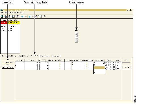
In the card view for the EC1 card, choose 0 or 1 on each of 12 ports.
In the card view for the OC-3 card, choose 0, or any number 1 through 3 on each port.
In the card view for the OC-12 card, choose 0, or any number 1 through 12 on each port.
In the card view for the OC-48 card, choose 0, or any number 1 through 48 on each port.
In the card view for the OC-192 card, choose 0, or any number 1 through 192 on each port.
Figure 8-1 Line tab for enabling pointer justification count parameters
Step 4
Step 5
Step 6
Step 7
Note
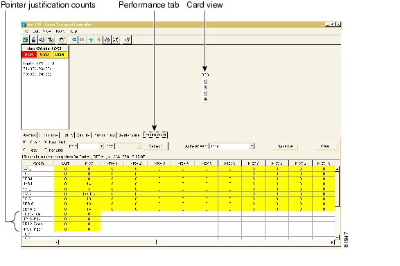
Figure 8-2 Viewing Pointer Justification Counts.
DLP-122 Enable Intermediate-Path Performance Monitoring
Note
Purpose
This task enables intermediate-path performance monitoring, which allows you to monitor large amounts of STS traffic through intermediate nodes.
Tools/Equipment
None
Prerequisite Procedures
If no STS circuit exists, use "Create Circuits and VT Tunnels" to create an STS circuit.
The circuit must pass through the EC-1 or OC-N card before you can enable IPPM on the circuit.
Required/As Needed
As needed
Onsite/Remote
Both
Step 1
See Table 8-1 for a list of Cisco ONS 15454 LTE cards.
Step 2
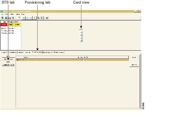
Figure 8-3 STS tab for enabling IPPM
Step 3
Step 4
NTP-74 Monitor Performance
Purpose
The Performance Monitoring screen allows you to monitor node performance in 15-minute intervals or 24-hour periods and to monitor near-end PMs or far-end PMs.
Tools/Equipment
None
Prerequisite Procedures
Before you monitor performance, be sure you have created the appropriate circuits and provisioned the card according to your specifications. For more information, see "Create Circuits and VT Tunnels" and "Change Card Settings."
Required/As Needed
As needed
Onsite/Remote
Onsite
Step 1
Step 2
Step 3
•
•
•
•
•
•
•
Step 4
DLP-123 View PMs
Purpose
This task enables you to view PM counts to detect performance problems early.
Tools/Equipment
None
Prerequisite Procedures
Before you view PMs, be sure you have created the appropriate circuits and provisioned the card according to your specifications. For more information, see "Create Circuits and VT Tunnels" and "Change Card Settings."
Required/As Needed
As needed
Onsite/Remote
Onsite or remote
Step 1
Step 2
Figure 8-4 Viewing performance monitoring information
Step 3
Step 4
DLP-124 Refresh PM Counts at Fifteen-Minute Intervals
Purpose
This task changes the screen view to display PMs in 15-minute intervals.
Tools/Equipment
None
Prerequisite Procedures
Before you view PMs, be sure you have created the appropriate circuits and provisioned the card according to your specifications. For more information, see "Create Circuits and VT Tunnels" and "Change Card Settings."
Required/As Needed
As needed
Onsite/Remote
Onsite or Remote
Step 1
Step 2
Step 3
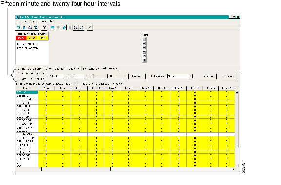
Figure 8-5 Time interval buttons on the card view Performance tab
Step 4
Step 5
Each monitored performance parameter has corresponding threshold values for the current time period. If the value of the counter exceeds the threshold value for a particular 15-minute interval, a threshold crossing alert (TCA) will be raised. The number represents the counter value for each specific performance monitoring parameter.
Step 6
Note
Step 7
DLP-125 Refresh PM Counts at Twenty-Four Hour Intervals
Purpose
This task changes the screen view to display PMs in 24-hour periods.
Tools/Equipment
None
Prerequisite Procedures
Before you view PMs, be sure you have created the appropriate circuits and provisioned the card according to your specifications. For more information, see "Create Circuits and VT Tunnels" and "Change Card Settings."
Required/As Needed
As needed
Onsite/Remote
Onsite or Remote
Step 1
Step 2
Step 3
Figure 8-6 Time interval buttons on the card view Performance tab
Step 4
Step 5
Each monitored performance parameter has corresponding threshold values for the current time period. If the value of the counter exceeds the threshold value for a particular 24-hour period, a threshold crossing alert (TCA) will be raised. The number represents the counter value for each specific performance monitoring parameter.
Step 6
Note
Step 7
DLP-126 Monitor Near-End PM Counts
Purpose
Use this task to view PMs on the near end.
Tools/Equipment
None
Prerequisite Procedures
Before you view PMs, be sure you have created the appropriate circuits and provisioned the card according to your specifications. For more information, see "Create Circuits and VT Tunnels" and "Change Card Settings."
Required/As Needed
As needed
Onsite/Remote
Onsite or Remote
Step 1
Step 2
Step 3
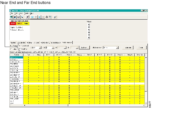
Figure 8-7 Near End and Far End buttons on the card view Performance tab
Step 4
Step 5
DLP-127 Monitor Far-End PM Counts
Purpose
Use this task to view PMs on the far end.
Tools/Equipment
None
Prerequisite Procedures
Only cards that allow far-end monitoring have this button as an option.
Before you view PMs, be sure you have created the appropriate circuits and provisioned the card according to your specifications. For more information, see "Create Circuits and VT Tunnels" and "Change Card Settings."
Required/As Needed
As needed
Onsite/Remote
Onsite or Remote
Step 1
Step 2
Step 3
Figure 8-8 Near End and Far End buttons on the card view Performance tab
Step 4
Step 5
DLP-128 Monitor PM Counts for Near-End or Far-End Signals
Purpose
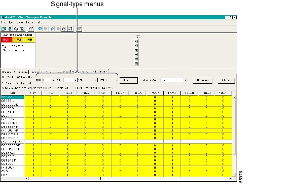
Use the signal-type menus to monitor PMs for near-end or far-end signals on a selected port.
Tools/Equipment
None
Prerequisite Procedures
Before you view PMs, be sure you have created the appropriate circuits and provisioned the card according to your specifications. For more information, see "Create Circuits and VT Tunnels" and "Change Card Settings."
Required/As Needed
As needed
Onsite/Remote
Remote
Step 1
Step 2
Note
Step 3
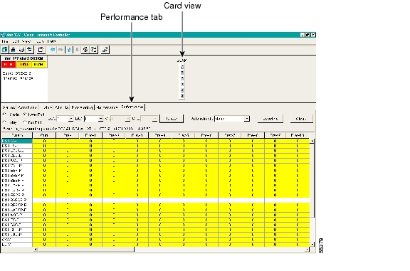
For example, the DS3XM card allows a selection of both the DS-3 port and the DS-1 within the specified DS-3. Figure 8-9 shows the signal-type menus on the Performance Monitoring screen for a DS3XM-6 card.
Figure 8-9 Signal-type menus for a DS3XM-6 card
Step 4
Step 5
DLP-129 Reset Current PM Counts
Purpose
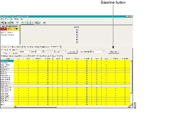
The Baseline button clears the PM count displayed on the Current column, but it does not clear the cumulative PM count. This allows you to see how quickly PM counts rise.
Tools/Equipment
None
Prerequisite Procedures
Before you view PMs, be sure you have created the appropriate circuits and provisioned the card according to your specifications. For more information, see "Create Circuits and VT Tunnels" and "Change Card Settings."
Required/As Needed
As needed
Onsite/Remote
Onsite or Remote
Step 1
Step 2
Step 3
Note
Figure 8-10 Baseline button for clearing displayed PM counts
Step 4
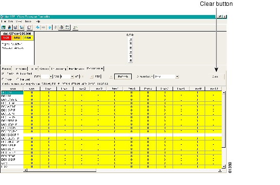
DLP-130 Clear Selected PM Counts
Purpose
Use the Clear button to clear certain PM counts depending on the option selected.
Tools/Equipment
None
Prerequisite Procedures
Before you view or clear PMs, be sure you have created the appropriate circuits and provisioned the card according to your specifications. For more information, see "Create Circuits and VT Tunnels" and "Change Card Settings."
Required/As Needed
As needed
Onsite/Remote
Onsite or Remote
Caution
Step 1
Step 2
Step 3
Figure 8-11 Clear button for clearing PM counts
Step 4
•
•
•
Step 5
Step 6
![]()
![]()
![]()
![]()
![]()
![]()
![]()
![]()
Posted: Fri Feb 22 14:08:21 PST 2008
All contents are Copyright © 1992--2008 Cisco Systems, Inc. All rights reserved.
Important Notices and Privacy Statement.